We have written about Tinkercad on our blog before. This is a free CAD-platform for beginners which is very easy to use, but doesn’t have many features.
Recently, we became aware of something called Tinkercad Circuits (“TC” henceforth), which is more aimed towards electronic circuits and Arduino coding rather than mechanical design, while still keeping the “for-beginners” profile.
TC actually has a lot going for it, and we’ll look at different aspects of it in this blog post. This is not a review, merely a first impression of TC.
The General Purpose of TC
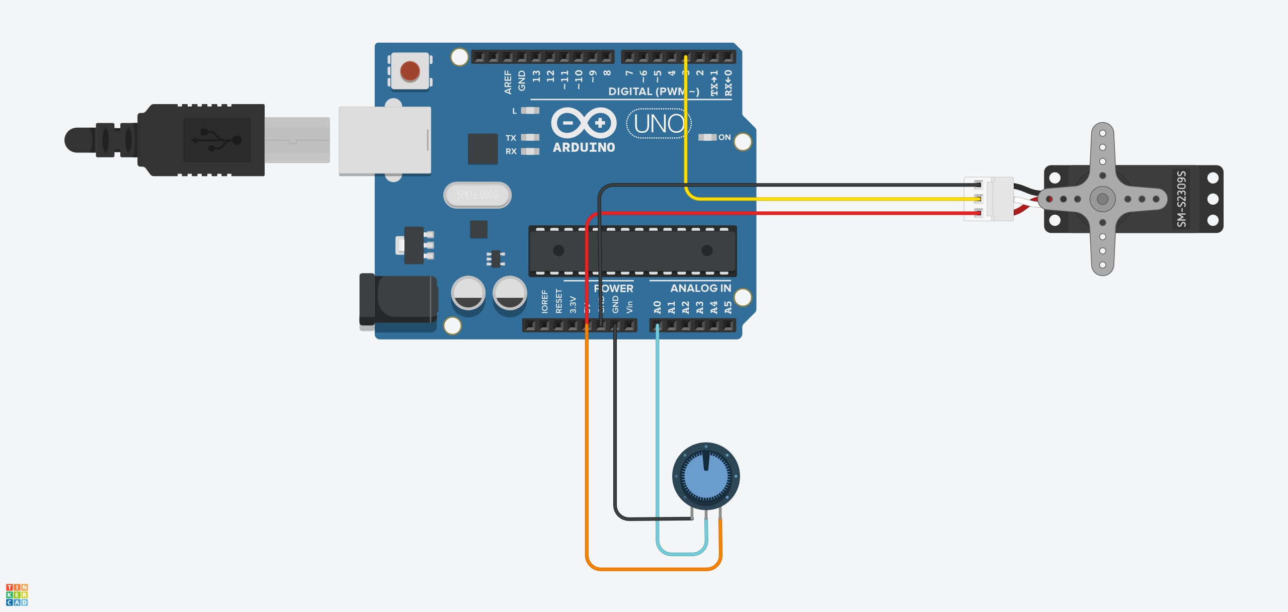
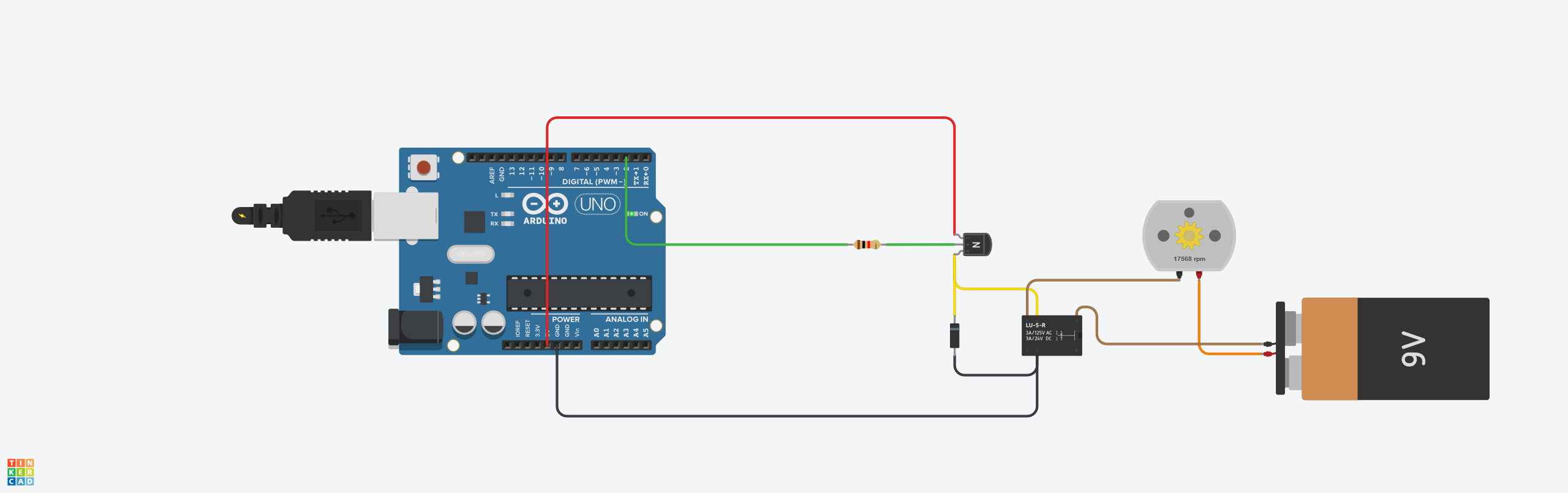
In TC you can hook a wide array of electrical components together, program an Arduino and simulate analog and digital behavior. Everything has a very intuitive and visual interface and it’s easy to just dive into it and start tinkering with a circuit. The simulations have some fun animations and sounds and, every component is nicely depicted.
TC is free to use (you do need an Autodesk account) and runs directly in your web browser.
Who Is This For?
Many beginners in embedded electronics may find TC as a nice tool for different purposes.
We can imagine that this can be used in pre-university education for introducing students to electronics and coding in a virtual low-effort, low-risk and low-cost environment.
Makers and DIYers who are new to embedded electronics can use this to learn about embedded systems, plan their next project or even generate their actual Arduino code (more on that later).
Components
The component library is larger than we expected, and sorted into different categories.
General
This is the category for passive components. Here you’ll find a resistor, two types of capacitors, two types of diodes and an inductor. Every component except the regular diode has basic configurable parameters.
Input
Here you’ll find 18 different components related to system inputs. These range from simple buttons and switches to more complex sensors, such as distance, motion and environmental sensors. During simulation you can manipulate these sensors in real time to simulate input.
Output
This category has 19 different output-related goodies such as LEDs, motors and displays.
Power
A category for batteries: 9 V, 1.5 V AA/AAA and 3 V coin cell. The AA/AAA batteries has some configuration parameters, such as how many batteries you want in series.
Breadboards
Three different breadboard sizes are available. Breadboards are not necessary for connecting components (you can just draw wires between them), but they can be useful when planning a real-life breadboard layout.
Microcontrollers
In this category you’ll find an Arduino Uno R3 and an ATtiny. How you program these is addressed further down in this blog post.
Instruments
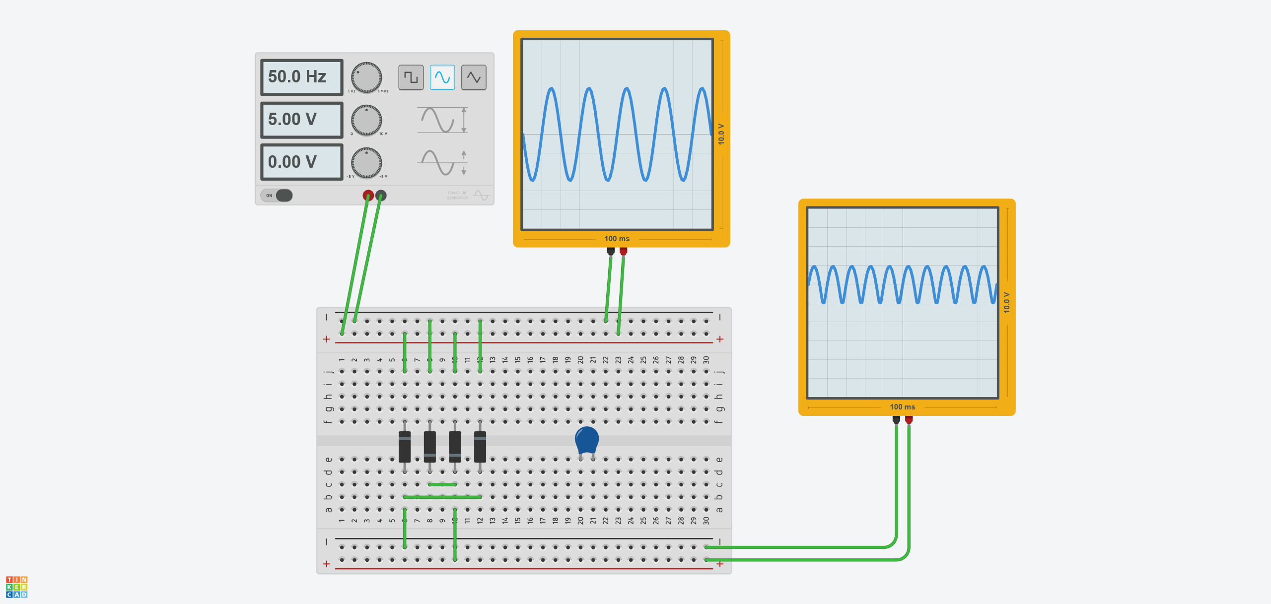
Here you will find a multimeter, a power supply, a function generator and an oscilloscope.
The multimeter can display current, voltage or resistance. The power supply has current limiting, while the function generator can generate square, sine or triangle waves at a given amplitude, frequency and DC-offset. The oscilloscope is very simplistic, but does have manual x-axis zoom and automatic y-axis zoom.
Integrated Circuits
This category consists of six different ICs, such as timers, an op-amp and comparators.
Power Control
A category consisting of seven types of transistors, two relays, two voltage regulators and two motor drivers.
Networking and Connectors
These are two different categories containing a total of 3 components.
Under Networking you’ll find a non-programmable ESP8266 Wi-Fi module. The usage of this in this simulated environment is currently unknown to us.
Under Connectors you’ll find a simple 8 pin header and a USB connector. Maybe some data is constantly being transferred on its data lines?
Logic
This is the last category and contains 19 different logic gates such as AND and OR gates.
Programming Microcontrollers
Programming microcontrollers can be done in one of two ways (or a combination of both):
- The traditional way with traditional Arduino coding.
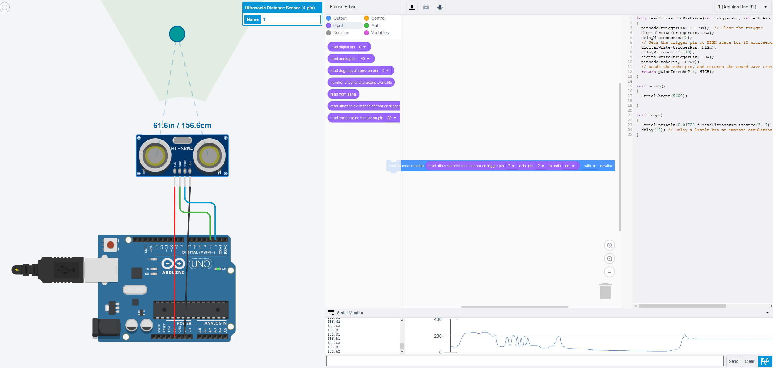
- A visual coding method by dragging boxes and placing them in a desired order. Code will then be generated automatically and continuously.
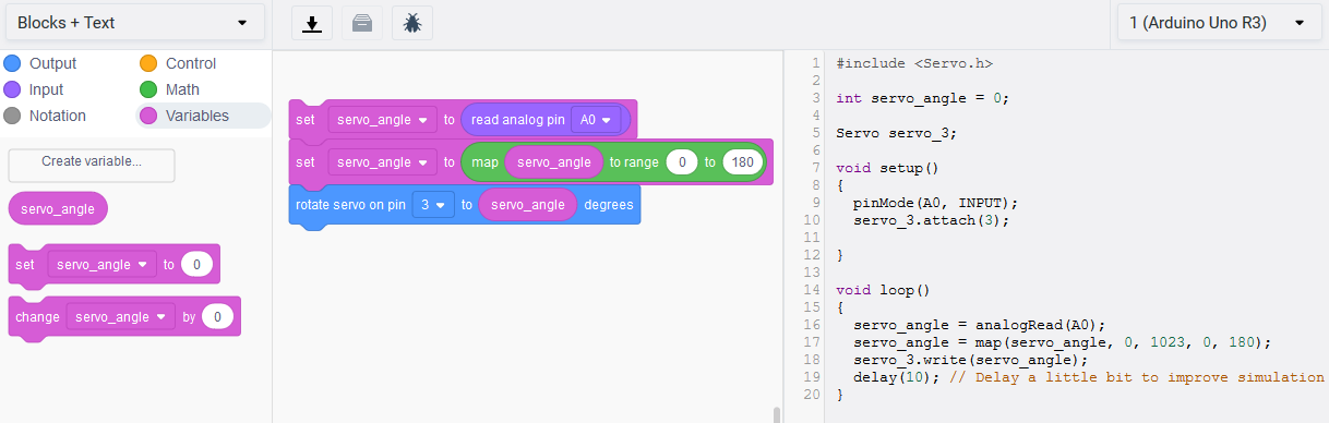
The flexibility with the visual method is surprisingly good, but when you’re used to coding the block dragging usually takes longer time than typing. The visual approach is, however, an excellent way of teaching programming to kids. Makers who don’t know how to code, but just want a simple program on an Arduino to work, can actually generate code this way and download the .ino file. It is optional to view either block view, text view or both.
The code is compiled online prior to simulation and the microcontroller is then simulated in real time. Both the Uno R3 and the ATtiny are coded in the Arduino language.
One thing, which is quite annoying, is that there is no undo/redo function for the coding, only for the circuitry. So if you accidentally throw your large chunk of code blocks in the bin, you have to start all over again.
Another thing we’re missing is the ability to resize the width of the different parts of the coding window. As far as we know, when having both the block and text view open, you can only resize the block part of the view.
Serial Communication
A very nice feature is the serial monitor, which is very similar to the one found in the Arduino IDE where you can send and receive serial data. They’ve even included the handy serial plotter, which is very cool.
Libraries
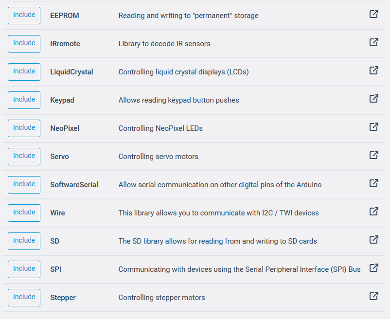
A few of the most common Arduino libraries can be included with easily accessible links to their respective documentation pages.
Other Features
Without having tried it, you can export the circuit to an Eagle .brd file. We advise that you use this function carefully. You can also export a simple components list.
The analog circuit simulation is not excellent and very simplified. For instance, adding a (required) capacitor to a rectifier circuit will just crash the simulation.
We found many things that we would include in a real circuits which are unnecessary in TC. In our motor control circuit further up in this blog post, neither the flyback diode nor the resistor is necessary to spare the transistor in the simulation. Additionally, many component properties are locked or just not simulated. Thus, circuits that work in TC might have problems in real life. Keep this in mind if using TC to design circuits.
Alternatives to TC
There are many other software solutions that does circuit simulation out there, but we haven’t really found anything just like TC. Virtual Breadboard might, by the looks of it, be the closest you get, but we haven’t tested it yet. Fritzing is another tool that looks a bit like TC, but it doesn’t have simulation as far as we know.
Falstad, Eagle, Partsim, Proteus VSM, Multisim, LTspice, Allegro PSPICE Simulator, OrCAD PSCPICE Designer, ngspice, TINA, TINA-TI, Qucs and Infineon Designer are some examples of software that does circuit simulation, sometimes in addition to circuit design. Some of these are free to use (and open source), and some are really expensive. Some are simple (e.g. simple simulation or only analog or digital circuits), and some are really heavy and complex with loads of features. All of the examples mentioned in this paragraph have probably more robust simulation features than TC, but all are also more difficult to use for beginners. Not all, but some of these examples also have microcontroller simulation like TC has, although a bit more complex, we’d assume.
Final Thoughts
Tinkercad Circuits surpassed our expectations since we weren’t that impressed by the original Tinkercad three years ago.
- Component selection: pretty good. There are many components to choose from, but it could always be more. 🙂
- Simulation: OK. Microcontroller simulation and simple circuitry works well, but it is pretty simplified and sometimes it can’t handle even relatively simple analog circuits.
- Coding features: good. An intuitive visual coding method with a pretty good functionality selection. Serial monitor, serial plotter and libraries are big pluses.
- General interface: pretty good. Easy to learn and use in general. Nice graphics and animations. Undo/redo functions for coding as well as more window resizing possibilities would be nice.
All in all, TC seems like a really nice platform for those people it is made for. Those of us who are a bit more versed in embedded system design should look elsewhere for useful software. We might, however, use this to later illustrate simple circuits on our blog, for instance.
Thumbs up!
January 4th 2019 – added “Alternatives” chapter.