Here at Norwegian Creations we use digital multimeters (DMMs) a lot. In fact, this is an essential tool to have if you want to play with electronics.
In this blog post a brief introduction and operation of a digital multimeter will be given.

Quick Intro
Digital multimeters come in a wide variety of models with different looks and feature sets. A basic DMM has the ability to measure Voltage, Current and Resistance. It’s also common to find continuity test and diode check modes.
More advanced models also include measurement for capacitance, inductance, temperature, frequency and duty cycle.
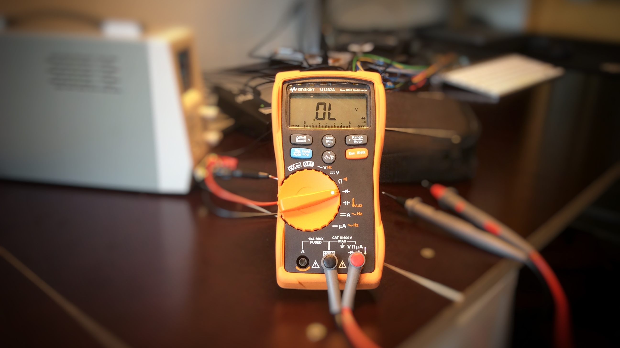
In this blog post we will use a Keysight U1232A multimeter to showcase the different modes. This is a mid range multimeter with all common features.
Please be aware that different DMMs all have different ways of selecting modes. Some have more combination buttons than other and such minor differences. However the basic principle behind measurement is the same across all models.
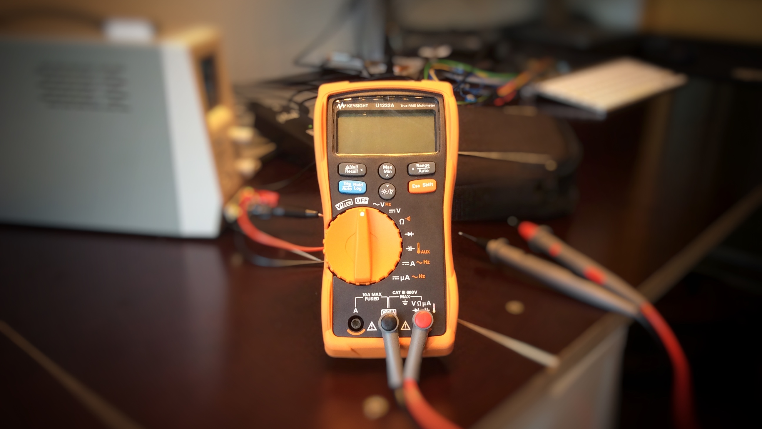
The mode selector
This is the single most important thing to get correct when working with multimeters. The mode selector also has other nicknames such as “Rotary Switch” and “Switch Selector”. This selects what you want to measure.
Here at Norwegian Creations we often see that selection of correct mode is a thing that many don’t get right when they are new to multimeters.
Several multimeters also have a “shift” function in combination with the mode selector, this gives a extra set of possible modes and they are often indicated with a different color around the mode selector.
Voltage
The key difference when measuring voltage is the selection between alternating (AC) and direct (DC) voltage.
Direct (DC V)
To measure voltage in direct voltage circuits you should look for the symbol with a solid line above a dashed line in combination with a “V”.
Alternating (AC V)
To measure voltage in alternating voltage circuits the “~” symbol is used on the multimeters. And since we want to measure voltage the “~V” combination is what you should look for.
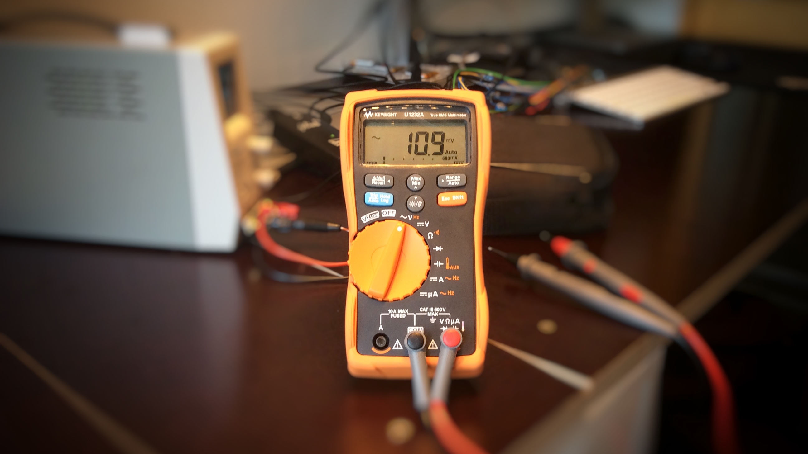
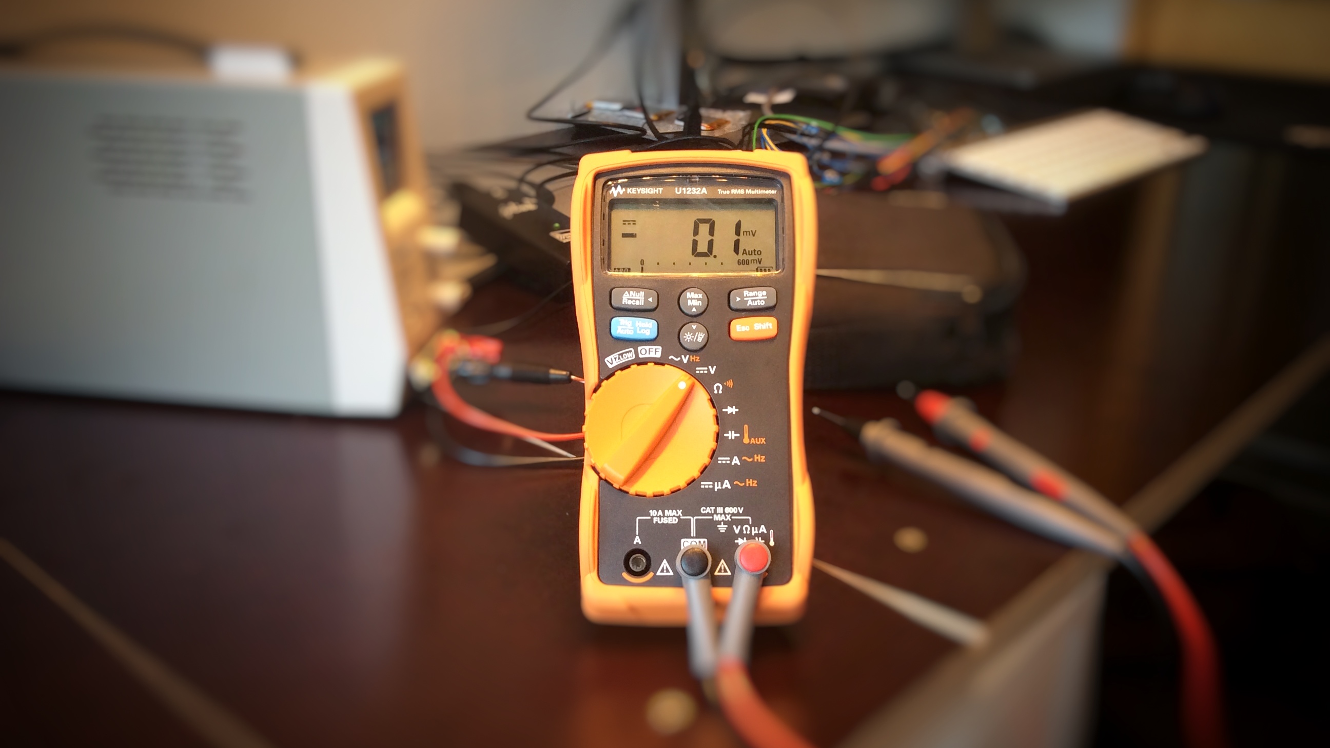
Millivolt and Microvolt
Some multimeters can also measure millivolt (mV) and microvolt (μV) ranges. On your multimeter look for the mV or μV around the mode selector. Remember to select the appropriate mode (AC / DC). This multimeter automatically changes into mV-range when appropriate, so no need to turn the mode selector here!
Current
Direct Current (DC A)
To measure the direct current look for the same symbol as measuring direct voltage, but now in a combination with an “A” (Ampere) instead of an “V”. Also know that the probes need to be connected in a way such that the current in the circuit will flow through the multimeter!

Please notice that you need to move the probe connection to the appropriate terminal on the multimeter. Otherwise you won’t be able to measure the current. Many multimeters do also have two separate current connections, one for A range and one for mA/uA range.
Alternating Current (AC A)
To measure the current in AC circuits look for the “~A” symbol. On the U1232A you can see that the mode is highlighted with orange. Therefore set the mode selector as the picture above and press the shift button once. You will then see that a “~” symbol will appear in the display.
Milliampere and Microampere
To measure milliampere look for “mA” on the multimeter. Our U1232A doesn’t have a dedicated milliampere range, so a measurement in the milliampere range is done by selecting the standard ampere mode as shown in the picture above. However, the U1232A does have a micro ampere range which is selected in the picture below.

When meassuring current be sure to measure within the appropriate ranges, or else you will blow some fuses inside the multimeter!
Resistance
To measure resistance select the mode illustrated with the “Ω” symbol.
The U1232A have auto range resistance measurement. This means it will automatically detect the correct range and measure the resistance.
Some models have manual ranging and you will have to manually select the appropriate range to get a measurement.
If you don’t know what range our best tip is just to start on one end and work you through the ranges.
Continuity
The continuity mode is a very nifty feature.
This mode is illustrated with a series of parallel arcs (“sound” symbol). With the continuity mode you can check if two things are electrically connected. The multimeter will beep if the two probes have electrical connection.
On the U1232A the continuity mode is a shift function on the resistance mode: select resistance mode (as the picture above), and then press shift button once. Your multimeter will now beep when the probes have electrical connection (something is “shorted“).
Diode Test
With the diode mode you can test if diodes are working correctly. The symbol used is a regular diode symbol.
The diode test mode will show you the forward bias voltage. This voltage is typically between 0.3 V to 0.8V. Remember that the diode test is polarity sensitive!
Tip: You could also use this mode to test LED’s. When you connect the probes to the LED it will emit a dim light indicating that it works and the polarity is correct!
Capacitance
The last mode in this blog post is the capacitance mode. With this mode you can measure the value of a capacitor.

Bear in mind that this mode hasn’t a very wide range. Don’t expect to measure the smallest or largest capacitors with a regular hand held meter. Are you unsure check the specifications of your multimeter to see its capabilities.
Final words
A good DMM accompanied by good “DMM-skills” is an important tool in the “Maker-toolbox”. We hope this blog-post helps you out with that 🙂
If it’s of interest we can dive more into advanced functions suchs as frequency counting, data logging and capasitor measurement.