This is part 1 of a planned short blog series about Boolean algebra and logic gates.
In this first part we’ll introduce you to simple Boolean algebra, which is very basic, and then look at how one or more logic gates can realize various Boolean functions.
[…] this is the very building blocks of all digital circuitry.
So why should you care about these topics? One reason is that this is the very building blocks of all digital circuitry. Every digital chip and computer can in essence be constructed with logic gates, which are based on Boolean algebra.
First Things First: Boolean Algebra
In Boolean Algebra, a variable can only have two values: 1 or 0, true or false, high or low, etc. This makes it relevant for those who dabble in digital electronic hardware or programming, but it’s also applicable in many other areas.
A Boolean function consists of one or more Boolean operations and “produces” a single Boolean value (which we for simplicity’s sake call output) from a set of other Boolean values (which we for simplicity’s sake call inputs). These inputs and outputs can only be 1 or 0. We’ll only use the term operation in this blog post, as opposed to function, from now on (again, to keep things a bit simple).
Basic Operations
We have three operations which is considered to be the most basic ones. These should be very familiar to those of you who’ve done a tad of programming.
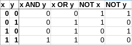
- AND (symbol ∧): all inputs need to be 1 to set the output to 1, otherwise the output is 0. (&& in C/C++).
- OR (symbol ∨): one or more of the inputs need to be 1 to set the output to 1, otherwise the output is 0. (|| in C/C++).
- NOT (symbol ¬): negates (inverts) the value of the input (only single input). (! in C/C++).
With these three operations we are able to form all other operations. Some of these we keep handy for convenience:
Secondary Operations
The next level of complexity comes in the shape of secondary operations. Here are some of them.
- Exclusive or (symbol: ⊕, aka. XOR): One and only one of the inputs must be 1 to set the output to 1. Otherwise, the output is 0. This is the most commonly used secondary operation.
- Material implication (symbol: →): sets the output equal to the second input if the first input is 1. Otherwise, the output is 1 (two inputs only).
- Equivalence (symbol: ≡): the output is 1 if all the inputs are equal. Otherwise, the output is 0. With two inputs this produces the opposite of XOR (see below).
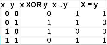
Material implication and equivalence are quite obscure. The most important one of these to be aware about is the XOR.
Inverted Outputs
The correct term is negation, but we’ll call it inversion in this blog post since we think it makes more sense.
Operations where the outputs are inverted are so commonly used that they have their own names:
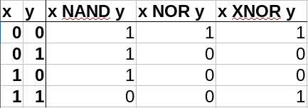
- NAND: AND with inverted output.
- NOR: OR with inverted output.
- XNOR: XOR with inverted output. XNOR is the same as equivalence as long as there are only two inputs.
Inverted Inputs
It is also common to invert the inputs of operations. A few rules/laws/fun-facts:
- Inverted inputs in an AND operation is equal to a NOR operation: ¬x∧¬y = ¬(x∨y)
- Inverted inputs in an OR operation is equal to a NAND operation: ¬x∨¬y = ¬(x∧y)
- Inverted inputs in a NAND operation is equal to an OR operation: ¬(¬x∧¬y) = x∨y
- Inverted inputs in a NOR operation is equal to an AND operation: ¬(¬x∨¬y) = x∧y
Inverting the inputs does not yield the same result as inverting the output!
There are a bunch of other laws as well, which you can read about here.
Logic Gates
While logic gates are a step towards the practice from the theory, we’ll keep it quite abstract for now. The thing you can keep in mind is that by using diodes and transistors (among other things) you can create real-life versions of these gates. In a 5 V logic electrical circuit, 5 V on a pin is the same as a Boolean 1, while 0 V on a pin is a Boolean 0.
By combining logic gates in certain ways we can make some pretty advanced behavior. But first the basics.
Basic Operations
This is what the basic operations look like when we draw them in electrical logic schematics.
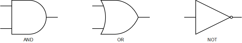 Notice the circle at the tip of the NOT gate triangle. This circle can be added on other gates, both on inputs and outputs, to invert either of them.
XOR
XOR has its own symbol which is shown at the top in the image below.
We can also create an XOR behavior, or module if you like, by connecting three different gates together as shown at the bottom of the image below. This is a simple example of how you can create more complex behavior by combining basic gates in a certain way.
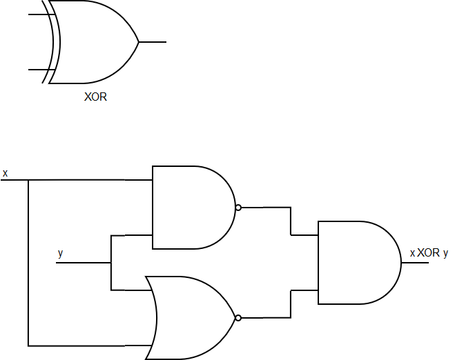
We can write this algebraically as x XOR y = (x NAND y) AND (x NOR y).
Invertions
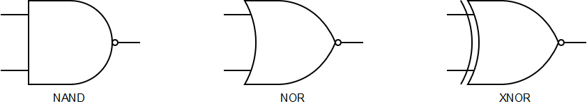
Here are the symbols for NAND, NOR and XNOR. Two of these were used in the XOR construction above.
Real Life Implementations
Let’s look at how an AND and an OR gate can be implemented in real life with transistors and diodes, respectively.
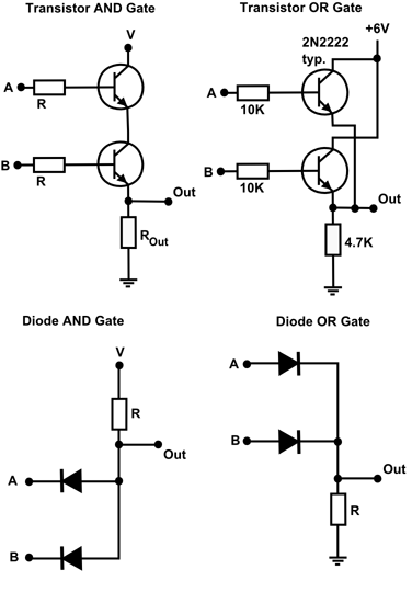
As you can see, you need two transistors to create either an AND or an OR gate. Inside a 2017 Nvidia GV100 Volta GPU chip there are as much as 21.1 billion (!) transistors. That’s roughly how many millimeters there are around the planet Mars.
Next Time
In the next episode of this series we’ll show you how you can create logic circuits which are a bit more advanced.