Operational amplifiers aka. opamps are electrical components that we haven’t previously touched upon in our blog. These components are important, though, so now we’re starting a series where we’ll introduce you to opamps and their usage. The opamp-topic can be quite the rabbit hole to enter, so we’ll start off easy and gradually increase the complexity over the course of this series.

Opamps were originally used in analog computers (before they became digital) to do both basic and more complex mathematical operations (addition, subtraction, multiplication, differentiation, integration, etc.). Opamps are still used for mathematical operations, but more commonly they are used to amplify analog signals. This is what we’re going to look closer at in this blog post.
Disclaimer: this post discusses the ideal opamp, just to simplify things a bit to give you an easier understanding of how things work. As you (should) know, unfortunately the real world isn’t ideal, so don’t take everything here too literally, especially the two golden rules.
The Component
An opamp is in schematics typically drawn like this (or a mirrored and/or flipped version):
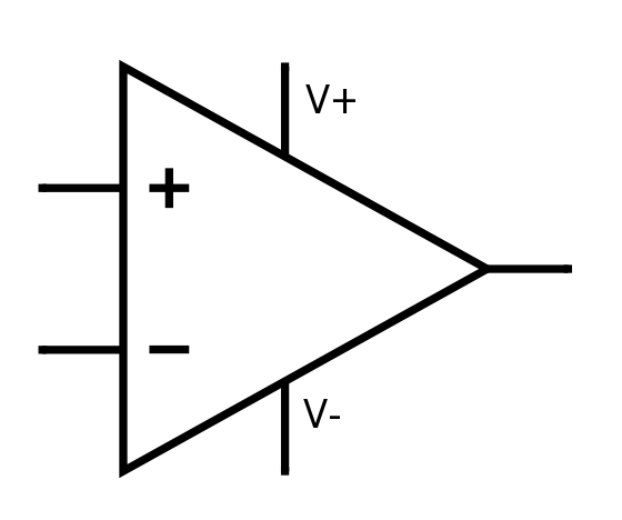
The + and – pins are the input pins, called non-inverting input and inverting input, respectively. V+ and V- are the power supply to the opamp, while the pin to the right is the output pin.
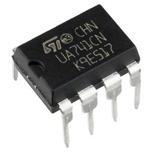
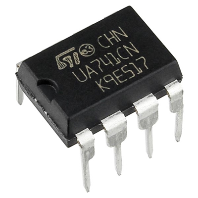
In real life, opamps can look like this:
 (Not) a Differential Amplifier
Although opamps essentially are differential amplifiers, which take the difference between the inputs and amplify it by an amount of gain, they are not designed to work this way on their own.
The internal gain in opamps is huge (a magnitude of 100,000), and this is why they can’t be used as differential amplifiers without some external circuitry. The output would saturate to V+ or V- no matter what. This property can however be utilized such that the opamp works as a comparator (outputs V+ if the non-inverting input is larger than the inverting input, and vice versa), but there are actual comparators out there that do this job better than opamps.
AC/DC
The opamp can handle any type of input signal, both AC and DC.
Various Configurations
The opamp is designed to have feedback, which is some connection between the output and one of the inputs.
The Two Golden Rules
This is the most important part of this blog post. Remember these two rules, and you’ll find the opamp to be much easier to understand:
- No current flows in or out of the inputs (non-inverting input and inverting input).
- The opamp will do its best to keep the two inputs at the same voltage level.
Rule #2 only applies in a feedback configuration, since the opamp only has control over its output.
Buffer
The first proper example of useful opamp usage we’re going to look at is using the opamp as a buffer, which is also the simplest.
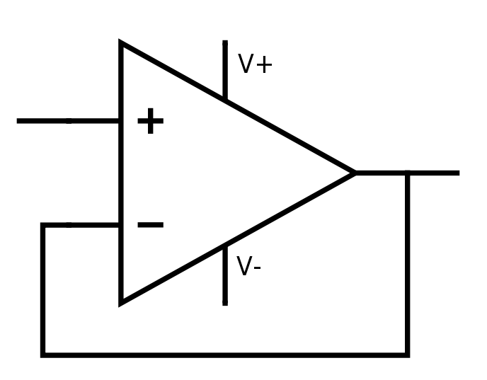
In the schematics above you can see an opamp buffer. Here we have a feedback from the output to the inverting input. Due to rule #2, the buffer will output a voltage equal to the voltage on the non-inverting input pin, as long as it is within the limits of V+ and V-. You might wonder what the point with this buffer is?
If you look at rule #1, no current enters (or exits) the input pins. The opamp will instead draw current from V+. This might be desirable if you have a sensor or something on the non-inverting input that you don’t want to disturb by drawing current from it.
Non-inverting Amplifier
Now, here we get into the meat of what the usefulness of the opamp!
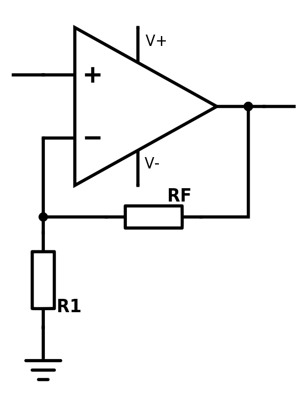 The opamp will set its output so that the inverting input matches the non-inverting input. This output voltage depends on the value of the resistors.
This configuration amplifies the signal on the non-inverting input with an amount of gain:
where AV is the gain which the signal is amplified by.
Inverting Amplifier
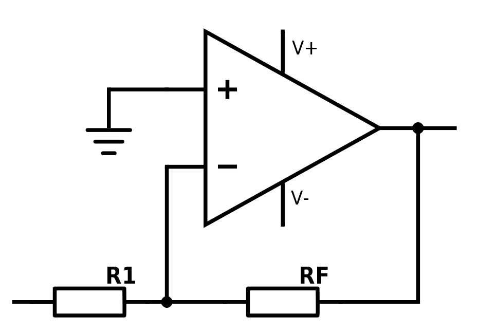
Here we have an inverting amplifier configuration. This is a bit harder to wrap ones head around, but we’ll do our best to explain a bit more in-depth:
Due to rule #2, the node between R1 and RF is the same voltage level as GND. The opamp will ensure this by driving the output to what it needs to be to acheive this. The node between these resistors is what we call virtual GND: it’s not connected to ground, but it has the same voltage level.
We apply voltage on the input, and get a voltage difference across R1. This means that current is flowing (Ohm’s Law) through the resistor. Rule #1 says that current can’t flow into the inputs on the opamp, so all of the current will continue through RF. Since we have current flowing through RF, we have a voltage drop (again, Ohm’s Law).
Let’s say R1 = 1 kΩ, RF = 2 kΩ and an input voltage of 1 VDC. The current through R1 (and RF) is:
and the voltage on the output pin is:
![]()
We set the current to be negative in the equation above for the math to be correct, because it is actually -2 VDC with respect to ground on the output pin of the opamp. With current flowing over a resistor, we always get a voltage drop. And if the voltage is already zero with respect to GND (which is the case at virtual GND) before the drop, we will get a negative voltage on the other side of the resistor RF.
To summarize, this configuration works just like the non-inverting amplifier, except that it also inverts the signal. The gain for inverting amplifiers is:
Note the absence of +1 at the end.
Differential Amplifier
We mentioned earlier that we can’t use opamps as differential amplifiers on their own. However, with feedback this becomes possible! Let us show you how:
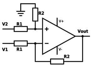
Look at the schematics above and imagine that V1 = V2. Due to rule #2, Vout will then be zero (equal to ground) to keep the inputs equal to each other. If V1 and V2 are different from each other, the opamp will compensate for this on the output.
The gain for this configuration is:
and the resulting Vout becomes:
One important aspect of differential amplifier configurations like this is that the resistors with the same name need to have as similar resistor value as possible.
Summarization
If you had no clue of what opamps do before, we hope you have gained some before reaching this bottom chapter. There are tons of opamp material to dig into, but we’ve tried to keep it light during this first look.
The most important thing to remember from this whole post is the two golden rules we listed. If you know these two, the rest is quite intuitive.
In future parts of this series we’re going to look at different types of opamps, various ways to apply them and different properties you should be aware of when selecting your opamps.