A couple of weeks ago we wrote an Arduino tutorial about potentiometers. This week we’re going to take a quick look at the pot’s close relative: the button. We will do a simple example circuit and code with an Arduino as well as explain the principles around pull-up resistors.
The Button/Switch
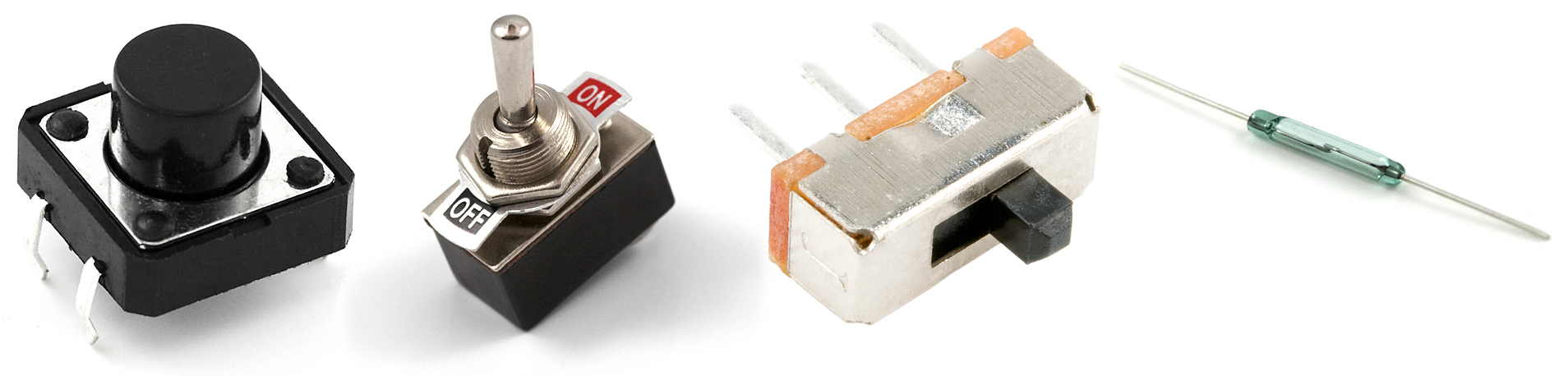
Buttons and switches come in many shapes and sizes. You have obviously seen a wide range of buttons and switches before, but what’s happening inside might not be that apparent. However, it’s really simple.
Imagine a castle drawbridge over a moat and that knights crossing the drawbridge are electricity. If the button is unpressed or open, the bridge is raised and knights are not able to cross: no flow of electricity. If the button is pressed or closed, the bridge is lowered and knights (electricity) can stroll freely across the bridge.
Arduino Example
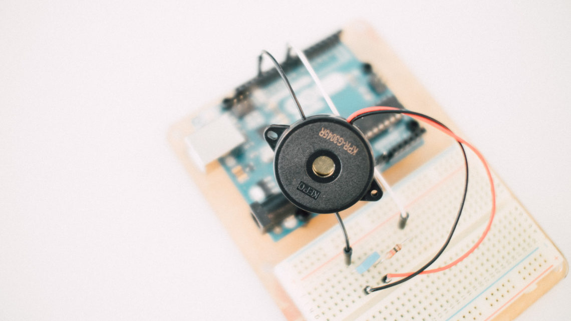
Similarly to the last Arduino tutorial, we’re going to keep things as simple as possible. Component-wise it will also be quite similar. You’ll need an Arduino (we’re going to use the Leonardo), a breadboard, a button or switch suitable for breadboards (we’ll use one of these), a few jump wires and a breadboard-friendly 10 kΩ resistor.
Arduino’s digitalRead() Function, HIGH and LOW
In the last tutorial about potentiometers, we used the analogRead() function to read the voltage on a pin and use the ADC. This time we’re going to use the digitalRead() function instead. This function doesn’t use the ADC, but instead checks if the voltage is above of below a certain threshold. On the 5V Arduinos, this threshold is at 3 volts. On the 3.3V Arduinos, the threshold is at 2 volts.
If the voltage read is above the threshold, digitalRead() will return the constant HIGH (boolean 1 or true). If the voltage read is below the threshold, the function will return the constant LOW (boolean 0 or false).
Circuitry and the Pull-up Resistor
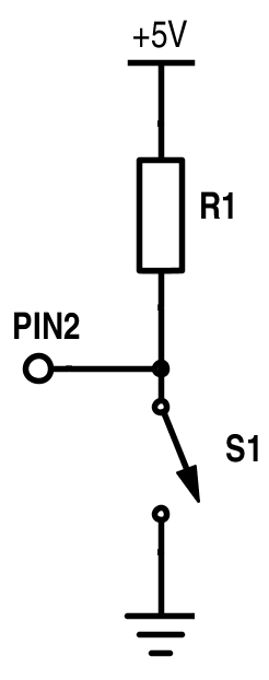 Above you can see the circuit we’re hooking up. R1 is a 10 kΩ resistor and S1 is our button (it even looks like a drawbridge in the schematics). Immediately you might wonder what the resistor and ground connection are doing there. Wouldn’t +5V -> switch -> PIN2 suffice? The answer is NO!
With the +5V -> switch -> PIN2 scheme, it’d work fine if we push down the button (i.e. close the circuit). PIN2 would then be 5V (i.e. HIGH). But when the button is unpressed, PIN2 would not be connected to anything, thus floating. This means that things get dicey: we’re not sure what the value read on PIN2 is. It can be either HIGH or LOW, we don’t know.
With the circuit in the schematics above, we avoid this problem! When the button is unpressed, the current will flow from +5V, through R1 and into PIN2. The current is next to zero, which makes the voltage drop over R1 also next to zero. This is more than enough to get a HIGH reading on PIN2 (refer to Ohm’s law for the math). The voltage read on PIN2 is equal to 5V minus the voltage drop over R1 (10,000Ω times the current flow in amps).
If we press the button, PIN2 will be connected directly to ground, thus be read as LOW. The voltage drop over R1 is now 5V, which results in an actual current flow (5V divided by 10,000Ω equals to 0.5mA) than when the button is unpressed.
If you switch positions of R1 and S1, R1 will become a pull-down resistor. Things will work just as well, but the voltage on PIN2 when pressing or depressing (not the sad kind of depressing) the button will switch as well. What you might want to consider when choosing between pull-up or pull-down resistors is the power consumption. If the button is rarely pressed, choose pull-up. If the button is pressed almost all the time, choose a pull-down. If you follow this rule, your embedded system will consume less power.
The Code
There are several combos one can do with different kinds of buttons/switches and software. The switch might be a push-button or a toggle switch. If you have a “stepless” button like us in this example, you’re still able to make a toggle switch out of it in software.
Similarly to the pot-tutorial, we’re going to print the result to the serial terminal. However, this time we don’t want to spam the terminal with binary button values. We only want to write to terminal when the button is pressed or depressed. To do this we need to use an extra variable and an if statement.
The rough flow of the code goes like this:
- Initialize global variables
- Set PIN2 as an input pin.
- Set up the Serial Module.
- The loop
- Read the voltage on PIN2
- Check if the value has changed since last time you checked
- If it has:
- Print the value to terminal
- Make sure you save the state of the button for the next check in step 4.2
- If it hasn’t: do nothing
- If it has:
Below is the actual code:
int inputPin = 2;
boolean last_state = false;
boolean state = false;

void setup(){
	pinMode(inputPin, INPUT);	//set PIN2 to input
	Serial.begin(115200);		//start the serial module at 115200 baudrate
}

void loop(){
	state = digitalRead(inputPin);	//read the voltage on PIN2

	if(state != last_state){		//check if the button state has changed since last time
		Serial.println(state);		//print to serial if it has
		last_state = state;			//save the button state
	}
}
As we’ve mentioned before: be sure to match the baudrate in the terminal with the one in the Serial.begin() function.
If you’ve set everything up correctly and run the code, you should se zeros and ones pop up in the serial monitor when pressing the button.
Conclusion
Beware that some buttons and switches might bounce a bit. That means that they mechanically can very quickly switch between on and off for a short while before settling down when pressing the button. There is a workaround to this which is called debouncing (both in HW and SW), but that’s a chapter for another time.
Hooking up a button like this is one of the simplest things you can do with the Arduino. But you have to start somewhere, right? Now that you know how to use both buttons and pots, you should also know how to control your embedded system. Remember that these methods we have gone through with pots and switches are applicable to many other sensors as well.