In this blogpost we will go through what a potentiometer is and how they work, how to connect it up to an Arduino as well as describe a common problem with regards to potentiometer usage and a workaround to that problem.
What Is a Potentiometer?
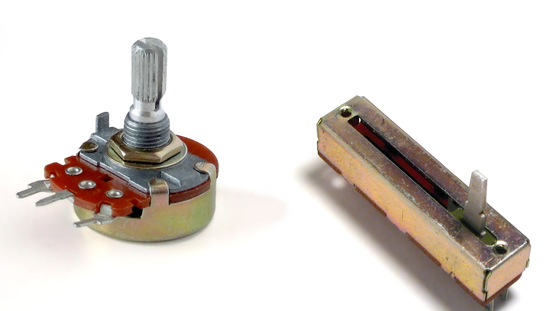
A potentiometer, henceforth referred to as a pot, is a variable resistor. It is an electrical component with three terminals (i.e. pins or legs): one for input voltage (e.g. 5V), one for output voltage (e.g. GND) and one for picking up the value of the pot (we’ll call this the wiper).
Mechanically speaking, pots are physically adjusted usually using your fingers. Both rotational and linear pots are common.
Pots are used a lot in all kinds of electrical appliances. Volume knobs, light dimmers and faders in audio mixers are often pots. They also come in digital and even motorized versions, but those are outside of the scope of this post.
If you want to control the speed of your electric motor, position of your servo, LED brightness, filter cutoff on your synthesizer, gain on your guitar amp or thousands of other cool things in your own embedded system, a pot might just be the solution for you.
The Theory
For an introduction to electrical theory, take a look at this post we wrote a while back where we explain fundamentals such as voltage, resistance and current as well as the relationship between these.
So, what’s happening in a circuit with a pot is basically voltage division in practice.
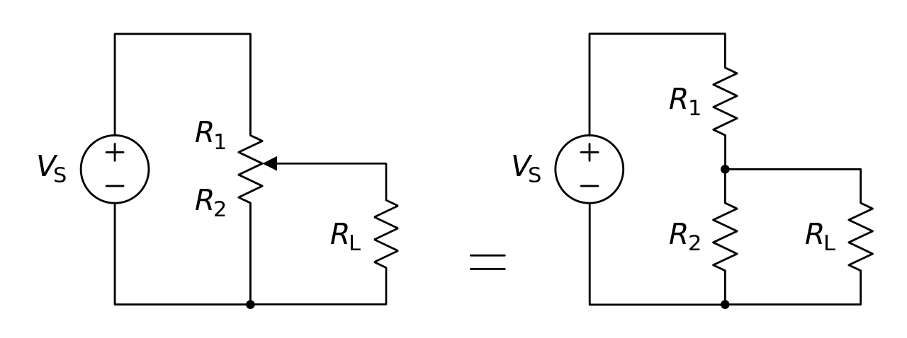
In the schematics above, the resistors R1 and R2 are part of the pot itself. RL is the resistance of the load (a motor, a LED or whatever). When you turn or slide the pot, you will change the values of R1 and R2. Moving the pot one way will reduce R1 and increase R2, and vice versa. This results in various voltage values on the wiper (the one that goes to RL in the schematics above). The voltage value itself can be calculated by using the following equation:
![]()
where VL is the voltage difference between the wiper and the output pin, and VS is the voltage difference between the input and output pin. To simplify this a bit: if the output pin is connected to GND, you can simply say that VL is the voltage on the wiper and VS is the voltage on the input pin (and then just ignore the “voltage difference” mumbo jumbo since GND is defined as 0V).
The Pot and the Arduino – an Example
Enough with the theory, let’s get things up and running with an example!
The Hardware
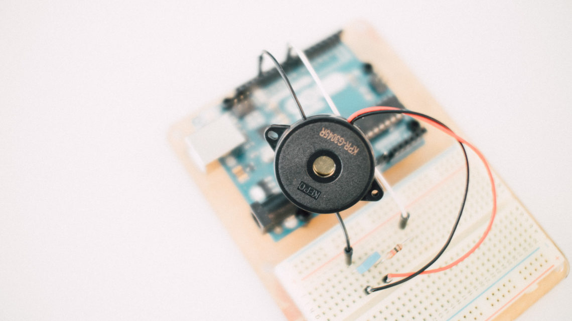
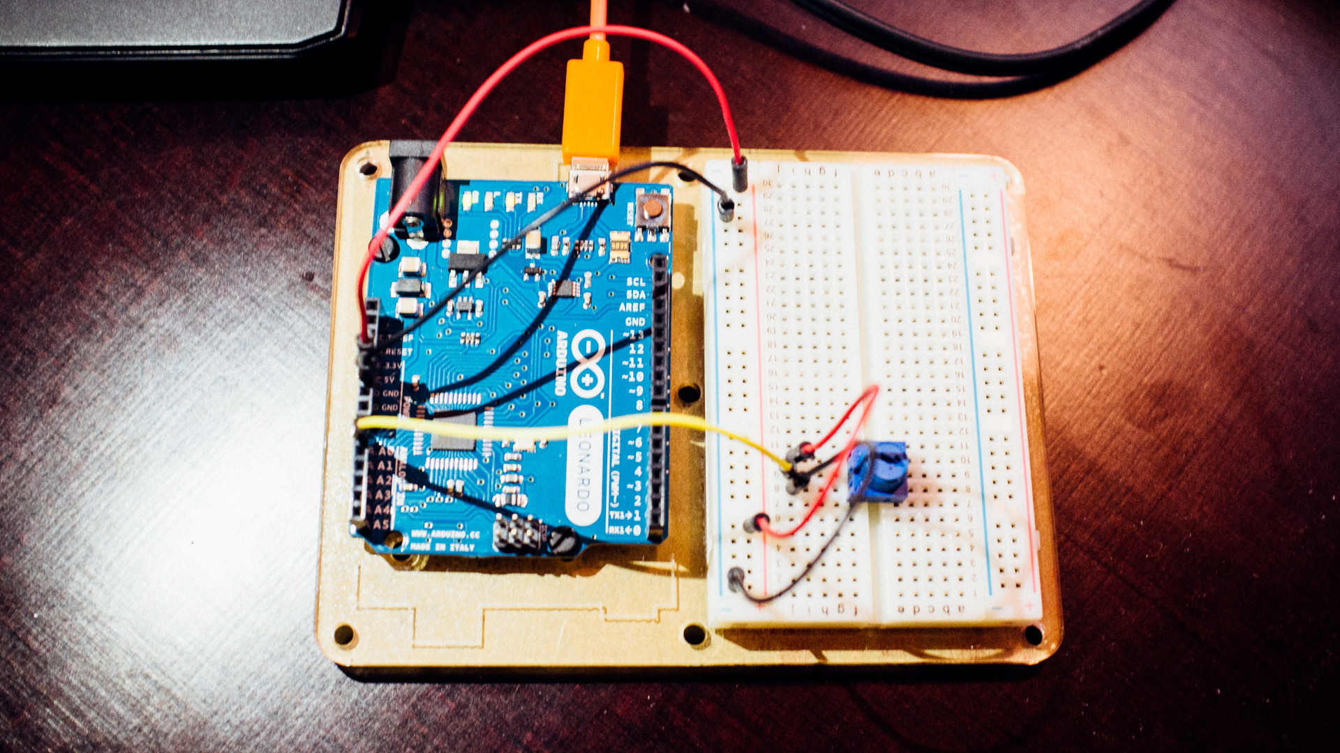
In the following example we’ve used a small 10K plastic pot for breadboard, a breadboard, a few jump wires (these are excellent for this purpose) and of course an Arduino (in this case a Leonardo).
We let 5V go to one of the pins on the sides of the pot and GND to the other. The middle one needs to go to one of the ANALOG IN pins on the Arduino, in this instance A0. And that’s it!
ADC (Analog-to-Digital Converter)
The signal from the pot is analog, but we want it to be digital so that we can read the value on the screen. Arduino has a built-in ADC (analog-to-digital converter) which creates a digital representation of the analog signal. The higher the input voltage, the larger the digital value. Arduino’s ADC takes in 0 to 5 volts and has a 10-bit resolution which lets it output 1024 digital values. To summarize: 0 volts is equivalent to a digital value of 0, and 5 volts is equivalent to a digital value of 1023.
You can read more about Arduino’s ADC here.
The Software
The most basic way to read the pot value is to print the digital value to the serial monitor, so that’s what we’re going to do.
The flow of this simple program will go like this:
- Initialize global variables.
- Set up the serial module.
- The loop
- Read the voltage of the pot and run it through the ADC.
- Write the digital value of the pot to the serial monitor.
- Wait 50ms before repeating.
Below is the code we’re running on the Leonardo:
//Global Variables
int sensorPin = 0;		//pin number to use the ADC
int sensorValue = 0;	//initialization of sensor variable

void setup(){
	Serial.begin(115200);	//setup of Serial module, 115200 bits/second
}

void loop(){
	sensorValue = analogRead(sensorPin);	//read the sensor value using ADC
	Serial.println(sensorValue);			//print digital value to serial monitor
	delay(50);								//50ms delay
}
When the code is up and running, open the Serial Monitor in the Arduino IDE to see the pot value change as you turn the knob. Remember to set the baudrate to the same value as in the serial initialization in the software (115200 in our case)!
A Common Problem and Filtering
If your software should react significally to changes on the pot (for instance change a major state) you’re gonna have a bad time. The reason for this is that while you’re not touching the pot, the values might change anyway. And the larger the resolution of your ADC is, the more probable it is that you encounter this measurement noise.
The reason for this issue is that the pot is continously adjusted and that it often is positioned in the middle of two digital values. Remember that the real world is not ideal, so tiny inevitable changes in the voltage from noise is enough to bump it back and forth between two or more digital values.
A Couple of Solutions
So, how do we cope with this? Firstly, don’t design your program so that a small change on the pot does something major.
Secondly, to reduce this measurement noise you can try adding simple low-pass filtering in the software. A moving average algorithm will often suffice. We will implement an exponential moving average algorithm, henceforth reffered to as EMA, to smooth out the signal in this example. Feel free to try out some of the other moving average algorithms as well.
The EMA algorithm goes as follows:
![]()
and for t>1:
![]()
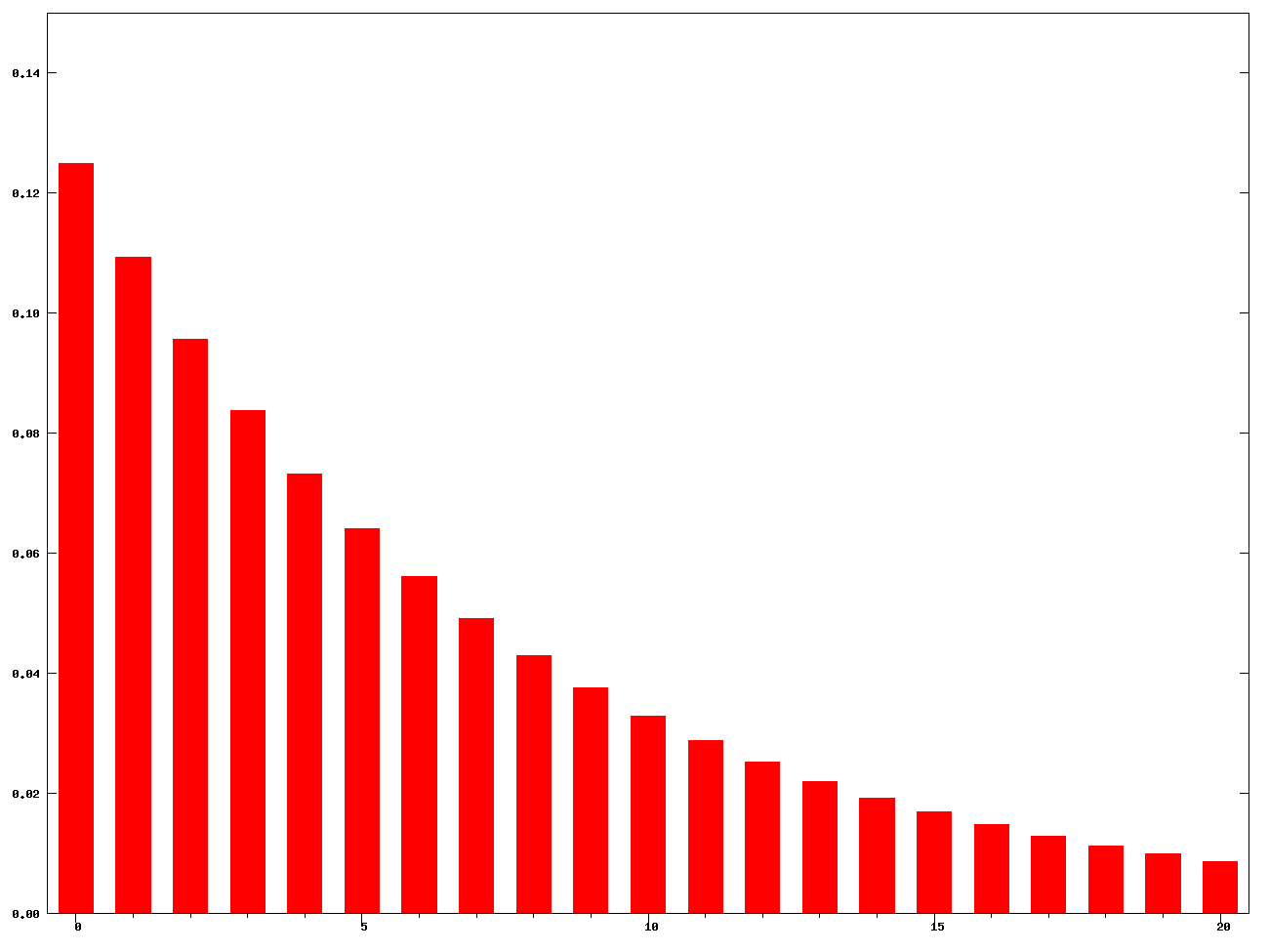
where St is the result of the EMA at time t, Yt is the pot measurement at time t, and α is a coefficient in the range <0,1> that decides how many samples the EMA algorithm should take into account. A low α will be very slow to rapid input changes and take many samples into account. A high α will be fast, but average over fewer samples. You can look at α as kind of a cutoff frequency in a low-pass filter.
Here’s the final code with the EMA:
//Global Variables
	int sensorPin = 0;		//pin number to use the ADC
	int sensorValue = 0;	//initialization of sensor variable, equivalent to EMA Y
	float EMA_a = 0.6;		//initialization of EMA alpha
	int EMA_S = 0;			//initialization of EMA S

void setup(){
	Serial.begin(115200);			//setup of Serial module, 115200 bits/second
	EMA_S = analogRead(sensorPin);	//set EMA S for t=1
}

void loop(){
	sensorValue = analogRead(sensorPin);				//read the sensor value using ADC
	EMA_S = (EMA_a*sensorValue) + ((1-EMA_a)*EMA_S);	//run the EMA
	Serial.println(EMA_S);								//print digital value to serial
	delay(50);											//50ms delay
}
Experiment with different values of α to see the difference in speed when rapidly changing the pot position.
Finding the actual cutoff-frequency is not trivial, but with some mathematical calculations it is possible. Take a look at this page to see how to do this.
You can use EMA to create quick and easy high-pass, band-pass and band-stop filters as well. If this sounds interesting, take a look at this blog post.
A Short Conclusion
We hope that this little tutorial was helpful to you. Potentiometers are super useful in embedded systems and really fun to play around with. Use them to control whatever you’d like! 🙂