In this post we’ll show you how to implement very simple high-pass, band-pass and band-stop filters on an Arduino.
It is highly recommended that you read our previous post about potentiometers and EMA (Exponential Moving Average) filtering as well as the one about plotting multiple values in the Arduino IDE before continuing since we use similar circuitry, filtering method and plotting method in this tutorial. We use a simple potentiometer and the ADC to create a signal we run through the filters.
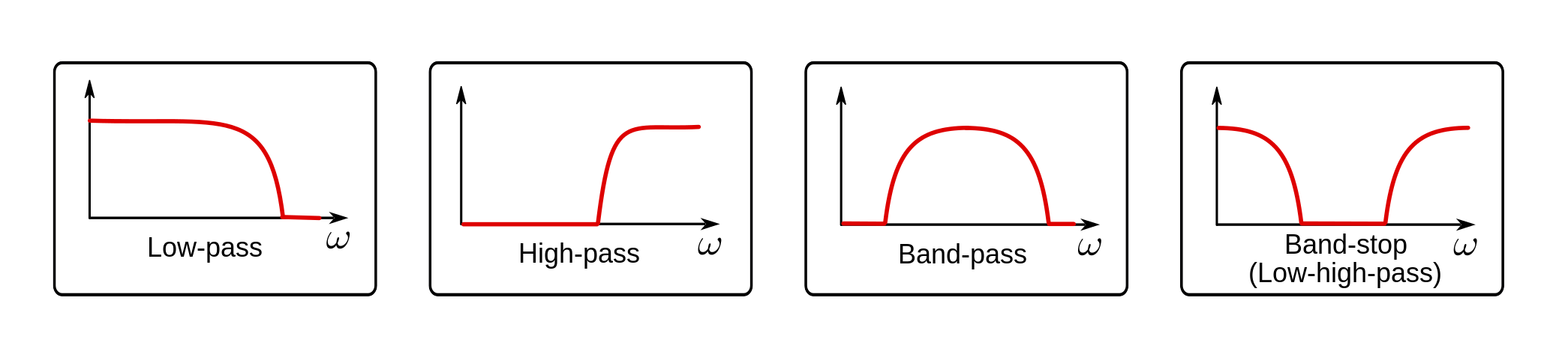
High-pass Filtering
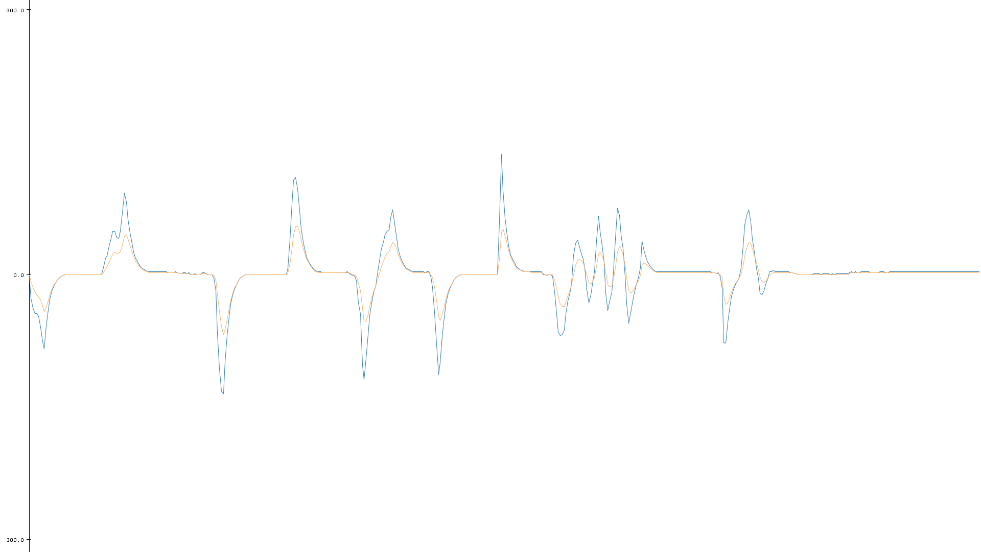
High-pass filtering is the opposite of low-pass filtering. Instead of smoothing out a signal, you’re left with all the noise and rapid changes. When the original signal stabilizes around any steady value, the high-passed signal goes to zero.
[…] run a low-pass filter and subtract the result from the original signal.
There are problaby more correct and efficient ways to implement high-pass filters, but the way we like to do it is to run a low-pass filter and subtract the result from the original signal. That way you’re left with only the high frequencies of the original signal.
This is the way we implemented it on an Arduino Leonardo:
//Global Variables
int sensorPin = 0;    //pin number to use the ADC
int sensorValue = 0;  //initialization of sensor variable, equivalent to EMA Y
float EMA_a = 0.3;    //initialization of EMA alpha
int EMA_S = 0;        //initialization of EMA S
int highpass = 0;

void setup(){
  Serial.begin(115200);              //setup of Serial module, 115200 bits/second
  EMA_S = analogRead(sensorPin);     //set EMA S for t=1
}

void loop(){
  sensorValue = analogRead(sensorPin);              //read the sensor value using ADC
  EMA_S = (EMA_a*sensorValue) + ((1-EMA_a)*EMA_S);  //run the EMA
  highpass = sensorValue - EMA_S;                   //calculate the high-pass signal

  Serial.println(highpass);

  delay(20);                                //20ms delay
}
Band-pass Filtering
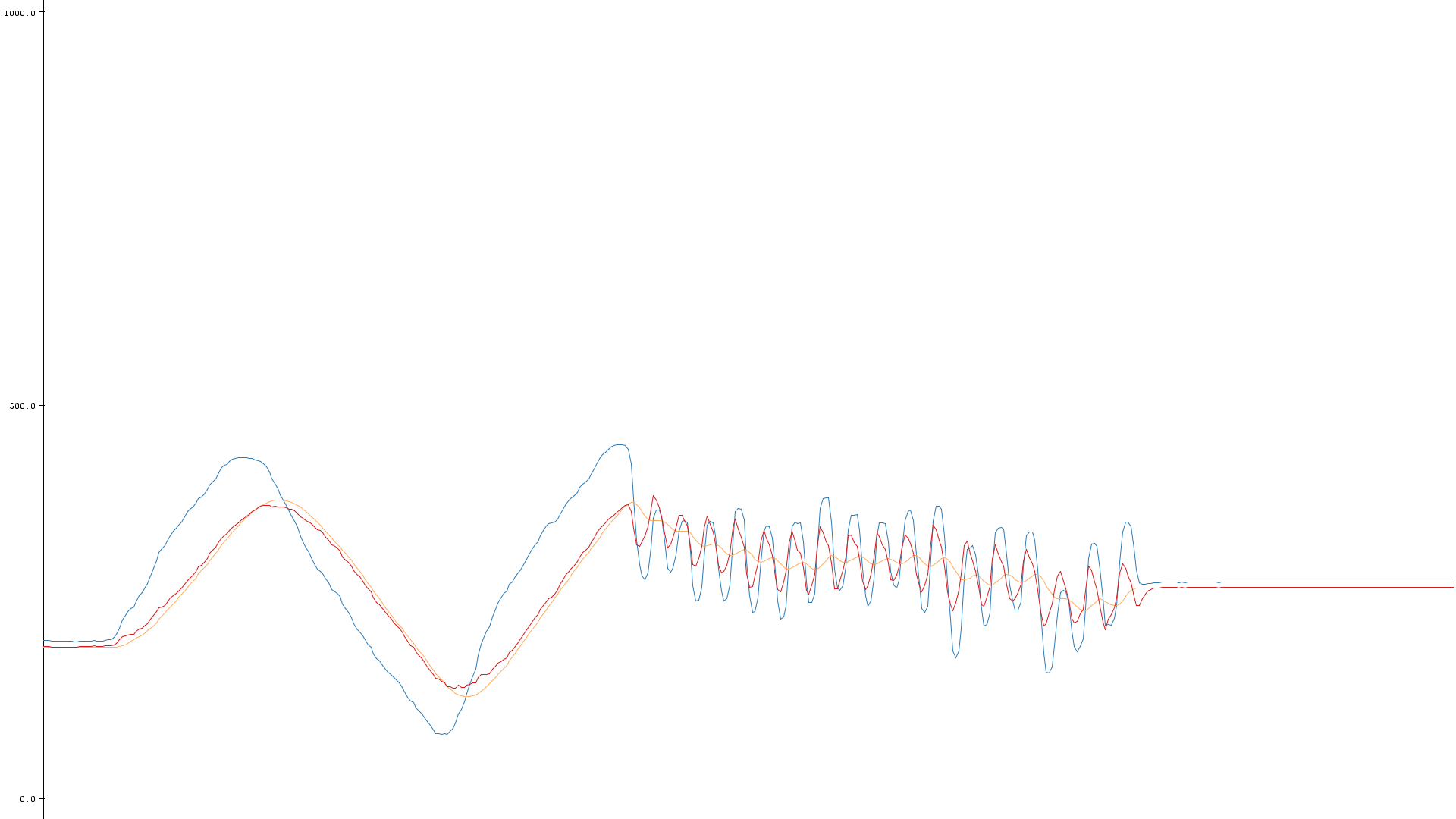
Imagine you have a high-pass filtered signal which is too noisy. Then a band-pass filter might be for you. A band-pass filtered signal is basically a smooth high-pass filtered signal.
[…] run two seperate EMA filters with different cutoff frequencies.
Our idea behind the implementation of a band-pass filter is that we run two seperate EMA filters with different cutoff frequencies. We then subtract the filtered signal with the lowest cutoff frequency from the filtered signal with the highest cutoff frequency. That way we’re left with the frequencies between the two cutoff frequencies, which both are crucial to get the performance you want from the filter.
Our implementation:
//Global Variables
int sensorPin = 0;        //pin number to use the ADC
int sensorValue = 0;      //initialization of sensor variable, equivalent to EMA Y

float EMA_a_low = 0.3;    //initialization of EMA alpha
float EMA_a_high = 0.5;

int EMA_S_low = 0;        //initialization of EMA S
int EMA_S_high = 0;

int highpass = 0;
int bandpass = 0;

void setup(){
  Serial.begin(115200);                   //setup of Serial module, 115200 bits/second

  EMA_S_low = analogRead(sensorPin);      //set EMA S for t=1
  EMA_S_high = analogRead(sensorPin);
}

void loop(){
  sensorValue = analogRead(sensorPin);    //read the sensor value using ADC

  EMA_S_low = (EMA_a_low*sensorValue) + ((1-EMA_a_low)*EMA_S_low);  //run the EMA
  EMA_S_high = (EMA_a_high*sensorValue) + ((1-EMA_a_high)*EMA_S_high);

  highpass = sensorValue - EMA_S_low;     //find the high-pass as before (for comparison)
  bandpass = EMA_S_high - EMA_S_low;      //find the band-pass

  Serial.print(highpass);
  Serial.print(" ");
  Serial.println(bandpass);

  delay(20);                              //20ms delay
}
Band-stop Filtering
This is the one that might be the most difficult one to wrap your head around. This filter only let the lowest and the highest frequencies through. This means that it differentiates itself quite a bit from the high-pass and the band-pass since it doesn’t return to zero all the time, but instead follows the steady value of the signal (like a low-pass filter). However, unlike a low-pass filter, it also includes high frequencies such as noise and rapid changes.
[…] subtract the band-pass filtered signal from the original signal.
Our idea behind this implementation is to subtract the band-pass filtered signal from the original signal. This ends up being an inverse band-pass filter. The two cutoff-frequencies are just as important here as in the band-pass filter.
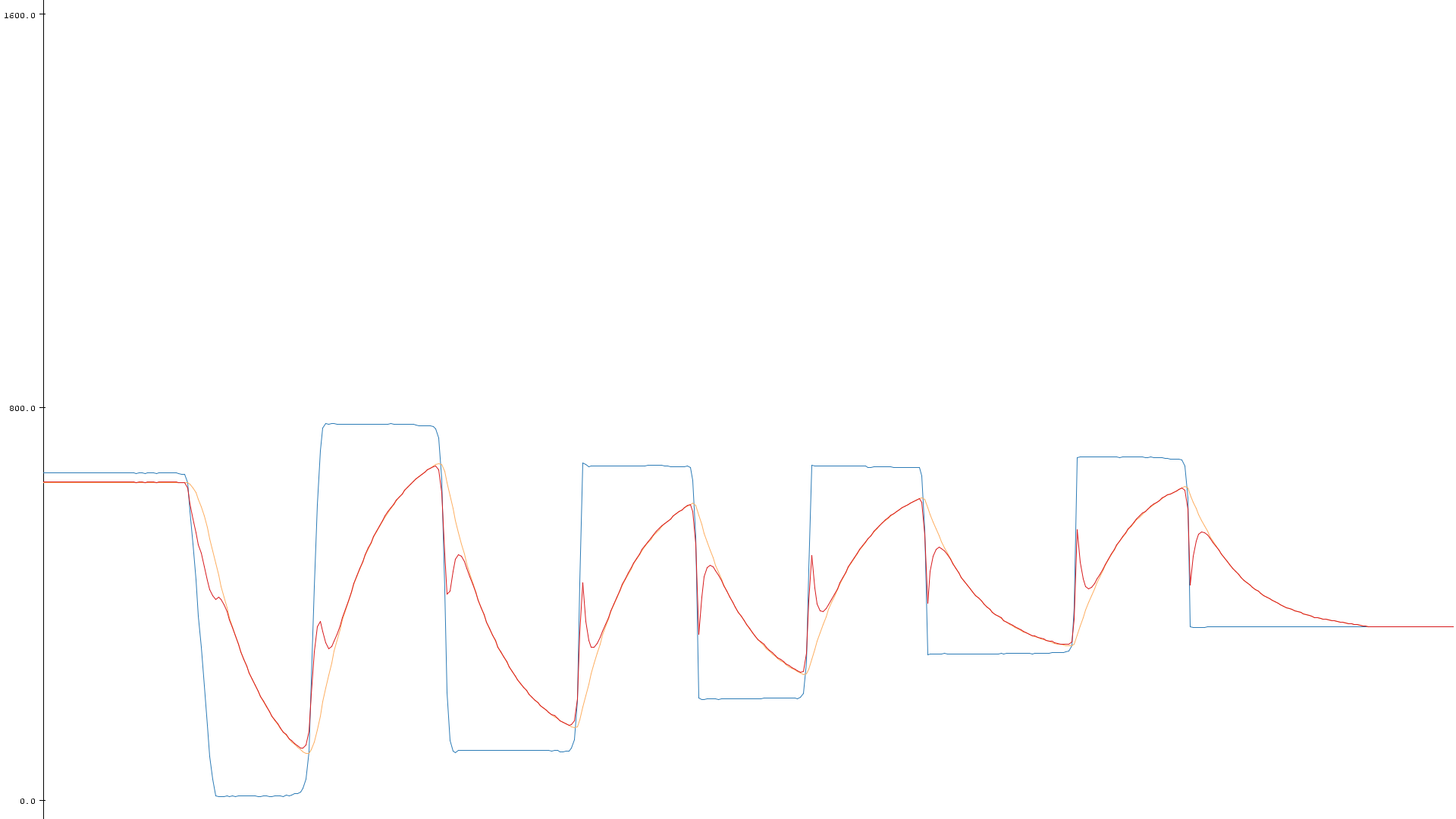
Our implementation:
//Global Variables
int sensorPin = 0;    		//pin number to use the ADC
int sensorValue = 0;  		//initialization of sensor variable, equivalent to EMA Y

float EMA_a_low = 0.05;		//initialization of EMA alpha (cutoff-frequency)
float EMA_a_high = 0.4;

int EMA_S_low = 0;			//initialization of EMA S
int EMA_S_high = 0;

int highpass = 0;
int bandpass = 0;
int bandstop = 0;

void setup(){
  Serial.begin(115200);              		//setup of Serial module, 115200 bits/second

  EMA_S_low = analogRead(sensorPin);		//set EMA S for t=1
  EMA_S_high = analogRead(sensorPin);
}

void loop(){
  sensorValue = analogRead(sensorPin);		//read the sensor value using ADC

  EMA_S_low = (EMA_a_low*sensorValue) + ((1-EMA_a_low)*EMA_S_low);  		//run the EMA
  EMA_S_high = (EMA_a_high*sensorValue) + ((1-EMA_a_high)*EMA_S_high);

  bandpass = EMA_S_high - EMA_S_low;  		//find the band-pass as before

  bandstop = sensorValue - bandpass;  		//find the band-stop signal

  Serial.print(sensorValue);
  Serial.print(" ");
  Serial.print(EMA_S_low);
  Serial.print(" ");
  Serial.println(bandstop);

  delay(20);								//20ms delay
}
The Small Chapter at the Bottom
As previously mentioned this is probably not the most efficient or most correct way to implement these kinds of filters. However, if you need some quick and dirty filter implementations, these ones might not be too shabby. Remember that the delay at the bottom of the loops in these examples are crucial for both the plotting rate and the filter characteristics.
Here is a nice guide on how to find the actual cutoff-frequency for EMA filters. This is applicable on these other filters as well, since we use EMA as a basis for all of them.
Try them out for yourself, play with the cutoff-frequencies and have fun!