This is the first part in a blog post series where we break down different objects in digital audio synthesis. This might make you able to answer the question “How does a digital synthesizer make all the awesome musical sounds?” so continue reading!
First we will look into a early and very critical block, namely the oscillator.
But what is it?
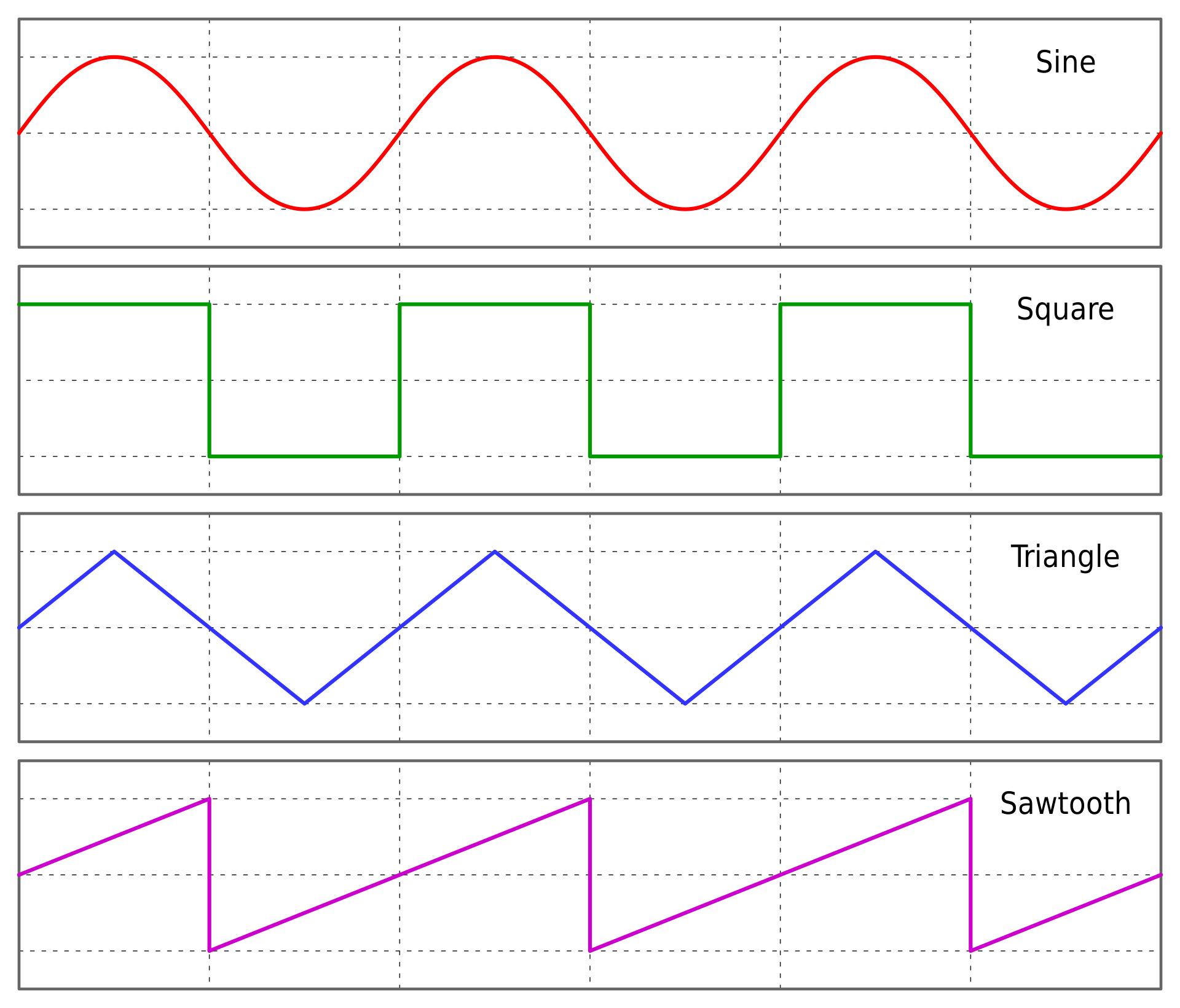
The oscillator is a signal generator that creates a waveform with different properties (such as shape, frequency and amplitude).
There exists many ways to create this oscillator, both analogue and digital. In this series we limit our self to the digital domain.
This post will delve into the creation of something called a “numerically-controlled oscillator“.
A numerically-controlled oscillator (NCO)
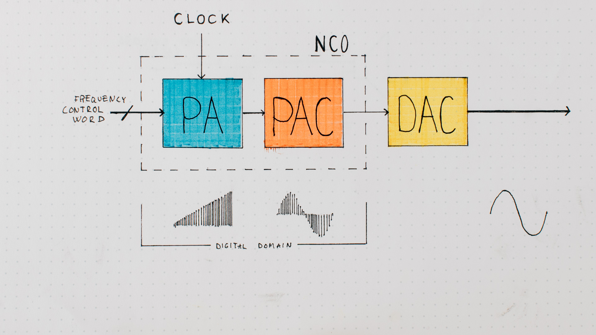
The numerically-controlled oscillator (NCO) consist of two main parts:
- The PA (phase accumulator) which creates the waveform phase.
- The PAC (phase-to-amplitude converter) which converts the waveform phase to amplitude.
The PA
The PA is made by incrementing a counter at a given frequency with something called a “Frequency Control Word”.
It’s always incremented at the same time-internal (period), but it is the “Frequency Control Word” that decides the output-frequency.
So a bigger word => faster incrementation of the phase accumulator => Higher frequency.
And when the phase accumulator reaches its top value, it wraps down to 0.
But this PA. How big is it (in bits)?
The bigger the PA is, a better frequency resolution is possible to achieve, but the downside is that it requires more computational resources to handle.
The AD9833 from Analog Devices is a “typical” waveform generator and has a PA of 28 bits.
The PA-input-clock. How fast does it need to go?
According to the “Nyquist–Shannon sampling theorem” it is possible to recreate a signal with anything higher than two ticks/waveform.
So in theory it is possible to go through the PA with a “Frequency Control Word” half the size of the PA.
But the PA frequency resolution (the smallest possible frequency change) is directly connected to the clock speed and the PA size. Higher speeds and/or lower PA-size = lower frequency resolution.

But what about turning the input clock speed down to increase the resolution? The clock is directly coupled to what the highest frequency possible to create. According to Nyquist we (only) need to give the PAC something to do twice/waveform so the NCO clock needs to be >= 2 * highest created frequency.
So if the NCO input clock runs at 100 kHz we can (in theory) create a waveform at 50 kHz..
The PAC
The PAC module converts the current calculated phase value to the waveform-amplitude. This should happen fast.
For more “complex” waveforms such as sinus, it’s common to store values in a look up table (LUT) and use the closest matching value from the table. But do you have a place to store this table?
And if you have some computational powers left you can do a linear interpolation when needed 🙂
But without storage or CPU-power? A lot of of chip tune music are created with waveforms easy and fast to generate such as sawtooths, square– and triangle-waves 😉
(The example later in this post generates a sawtooth-wave from the PA-value)
The PAC creates the amplitude of the waveform from the phase
Example
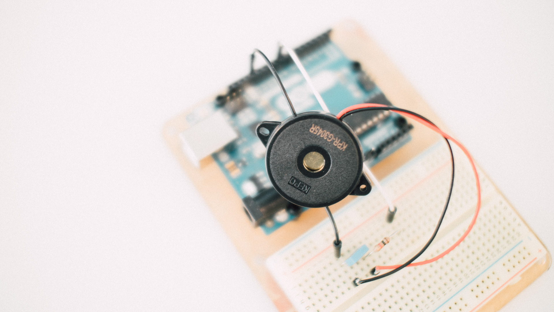
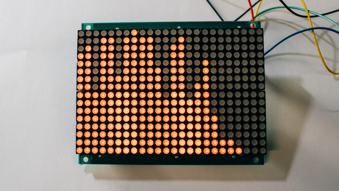
This example is a “quick-and-dirty” approach to creation of a simple NCO. It’s done on a Arduino UNO to make it easy to understand, and simple to recreate by yourself.
The highest frequency we wish to create is around 7 kHz and the frequency resolution needs to be > 0.5 Hz.
With the “Nyquist–Shannon sampling theorem” in our hand we decide that our NCO-clock needs to be at least 14 kHz.
And by plugging that into the F_RES formula we get out that with a PA on 14.8 bits is enough to gives us a frequency resolution on 0.5 Hz.
But a variable size on 14.8 bits are a bit impossible to create, so we are rounding this up to 16 (giving us a frequency resolution on 0.21 Hz).
As we can see later in this example, due to the timer divisors available in the ATmega328p and the external clock frequency, did the main NCO-clock frequency land on 15.625 kHz (62.5 kHz / 4 as later explained)
Signal output
We need to convert the sample residing in the digital domain to an analogue one. This can be done with an external DAC.
But for the sake of simplicity are we outputting the audio through a simple 8-bit(!) PWM-DAC on the Arduino UNO.
And to somewhat reduce the level of unwanted noise we will run the PWM frequency 4 times higher than the sample frequency.
To output the sound we used a piezo trancducer, and this was wired into the circuit after a LP-filter with resistor on 1 kOhm and a capacitor on 0.1 uF.
This 1st order passive RC-filter gives us a cutoff frequency around 1.6 kHz, which is somewhat low, but we are not actually creating tones with as high frequency as first wished, so that is okey for now.

Note that this DAC-method introduces much noise to an already low fidelity system
The signal-to-noise ratio of this 8-bit system are lower than ~50 dB (because the PWM-DAC introduces several dB of unwanted noise and also reduces the THD several steps!).
The 8-bit PWM-DAC used here could also be improved many times by introducing adding better filtering in combination with a buffer/amplifier 🙂
Calculating the word sizes for the different frequencies?
The different note frequencies can easily be calculated or looked up in a table like this.
And after you have found the notes of interest you can calculate the different “Frequency Control Words” using this formula:

It’s possible to do this calculation “on the fly” inside the microcontroller, but please think about your available calculation resources;)
The PA and the PAC
The PA is a 16-bit up-counter that increment the “Frequency Control Words” (which automatically wraps around when full). [line 60-63].
The PAC is also rather simple. It creates a sawtooth waveform by using the top 8 bit in the PA result directly! [line 65-68].
They are both executed inside an ISR [line 51], something done only because they are completed long before the next interrupt and no other interrupts can occur.
The code
#include <avr/io.h>
#include <avr/interrupt.h>

#define PWM_pin   9             // This is the OC1A-pin

volatile uint8_t counter = 0;
volatile uint16_t phase_accumulator = 0;
volatile uint16_t control_word = 0;

volatile uint8_t sample = 0;

void play_song(void);

void setup()
{
  pinMode(PWM_pin, OUTPUT);

  // turn off interrupts
  cli();

  // Set up Timer1 (cause millis() uses Timer0) to provide Fast 8-bit PWM
  //   and activate an ISR at every TOP
  // Clear the OC1A-pin (Arduino pin 11) on compare match with OCR1A (non-inverting mode)
  TCCR1A = (1 << COM1A1) | (1 << WGM10);

  // make sure the PWM-output is initialized to zero
  OCR1A = 0;

  // Set it up so we have a PWM period > 4 * 14kHz (and TOP = 0xFF)
  // Prescaling = 1 means it runs at 16 Mhz (the main clock)
  // => giving a PWM period on 62.5 kHz (because TOP = 0xFF)
  TCCR1B = (1 << CS10) | (1 << WGM12);

  // Timer/Counter1 Overflow Interrupt Enable
  TIMSK1 |= (1 << TOIE1);

  // turn on interrupts
  sei();
}

void loop()
{
  while(1)
  {
    play_song();
    delay(10000);
  }
}

// This is the Timer1-interrupts that fires on 62.5 kHz
ISR(TIMER1_OVF_vect)
{
  // Let the PWM send out the sample (at least!) 4 times for every sample!
  // Not so clever to calculate PAC+ in this ISR,
  //   but we can get away with it here because so little other tasks and simple waveform
  if ( counter >= 4 )
  {
    counter = 0;

    // PA-section ////////////////////////////

    // increment the PA
    phase_accumulator += control_word;

    // PAC-section ///////////////////////////

    // create a saw from the phase_accumulator
    sample = (uint8_t) ( phase_accumulator >> 8 );

    // Realization ///////////////////////////
    // set out the new sample on the PWM module
    OCR1A = sample;
  }

  counter++;
}

//// THE "MUSIC" ///////////////////////////////////////////////////////////////////

// Note                   control word delta
#define NOTE_OFF          0

#define NOTE_E4           1384
#define NOTE_F4           1464
#define NOTE_F4_UP        1552
#define NOTE_G4           1648
#define NOTE_G4_UP        1744
#define NOTE_A4           1848
#define NOTE_A4_UP        1952
#define NOTE_B4           2072

#define NOTE_C5           2192
#define NOTE_C5_UP        2328
#define NOTE_D5           2464

// This function includes a blocking delay for the note duration!
// play speed denotes bpm
// note_duration: 4 = quarter note, 8 = eighth note etc.
// control_word_delta: The value to apply to the PA. This is the "frequency"!
void play_note(uint8_t play_speed, uint8_t note_duration, uint16_t control_word_delta)
{
  control_word = control_word_delta;

  // insert a short pause after each note to break things up
  uint8_t pause = 250 / note_duration;

  // 240000 because because play_speed is referring to number of q-notes / min.
  uint32_t delay_time = 240000/((uint32_t)play_speed)/((uint32_t)note_duration);

  // only deduct the short pause-time if possible!
  if ( delay_time >= pause )
  {
    delay( delay_time - pause );
  }

  // stop the tone
  control_word = 0;

  // insert a short pause after each note
  delay(pause);
}

void play_song(void)
{
  uint8_t tempo = 200;

  play_note(tempo, 4, NOTE_D5);
  play_note(tempo, 4, NOTE_B4);
  play_note(tempo, 2, NOTE_D5);

  play_note(tempo, 4, NOTE_C5_UP);
  play_note(tempo, 4, NOTE_A4);
  play_note(tempo, 2, NOTE_F4_UP);

  play_note(tempo, 4, NOTE_E4);
  play_note(tempo, 4, NOTE_G4);
  play_note(tempo, 2, NOTE_E4);

  play_note(tempo, 4, NOTE_F4_UP);
  play_note(tempo, 4, NOTE_A4);
  play_note(tempo, 2, NOTE_F4_UP);

  play_note(tempo, 1, NOTE_A4);

  play_note(tempo, 1, NOTE_F4_UP);

  play_note(tempo, 4, NOTE_E4);
  play_note(tempo, 4, NOTE_G4);
  play_note(tempo, 2, NOTE_E4);

  play_note(tempo, 4, NOTE_F4_UP);
  play_note(tempo, 4, NOTE_A4);
  play_note(tempo, 4, NOTE_F4_UP);
  play_note(tempo, 4, NOTE_F4_UP);

  play_note(tempo, 1, NOTE_B4);
}
Result
This is a very long way from high fidelity sound.
But why is it so?
Some of the first big improvement points are:
- Increase the sampling rate. Only 16 MHz / 256 / 4 = 15,625 kHz here. Regular Audio CDs uses 44.1 kHz sampling rate
- Increase the sample size. Only 8 bits here. Regular Audio CDs uses 16 bits for each sample
- Change the DAC-type. An 8-bit 4 * samplerate-PWM-DAC is used here
Next steps
Currently we are a long way from nice audio! So how is it done? How does a digital synthesizer make all the magic sounds?
An oscillator as presented in this post is a common start, increasing the bit-depth, the sample-rate and changing the DAC is some early wins (demo of that in a later part!).
If we continue down this rabbit hole of emulating an analog synth in the “digital domain“, we should add some filtering to the signal. Then some envelope generation (triggered by note inputs). This envelope could also control the filter for more awesomeness!
We could also add some audio effects to the signal (chorus, delay, flanger etc.).
All this should of course be easily controllable, and to do that we could give the system a way to understand MIDI.
As you can see: The TODO-list grew very fast! And this happened before mentioning another awesome way to generate waveforms; namely FM synthesis. And what about sample-based synthesis?
We will start to delve into these topics in upcoming blog posts, so stay tuned!