Behavior adjustment based on system voltage is often both possible and beneficial 🙂
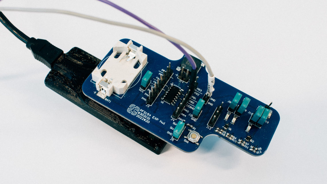
In this post we will use the 2022 Christmas card as an example.
What is it?
In a system where the input voltage is not constant through the operational time, it can be of great benefit to change the behavior based on the changing input voltage
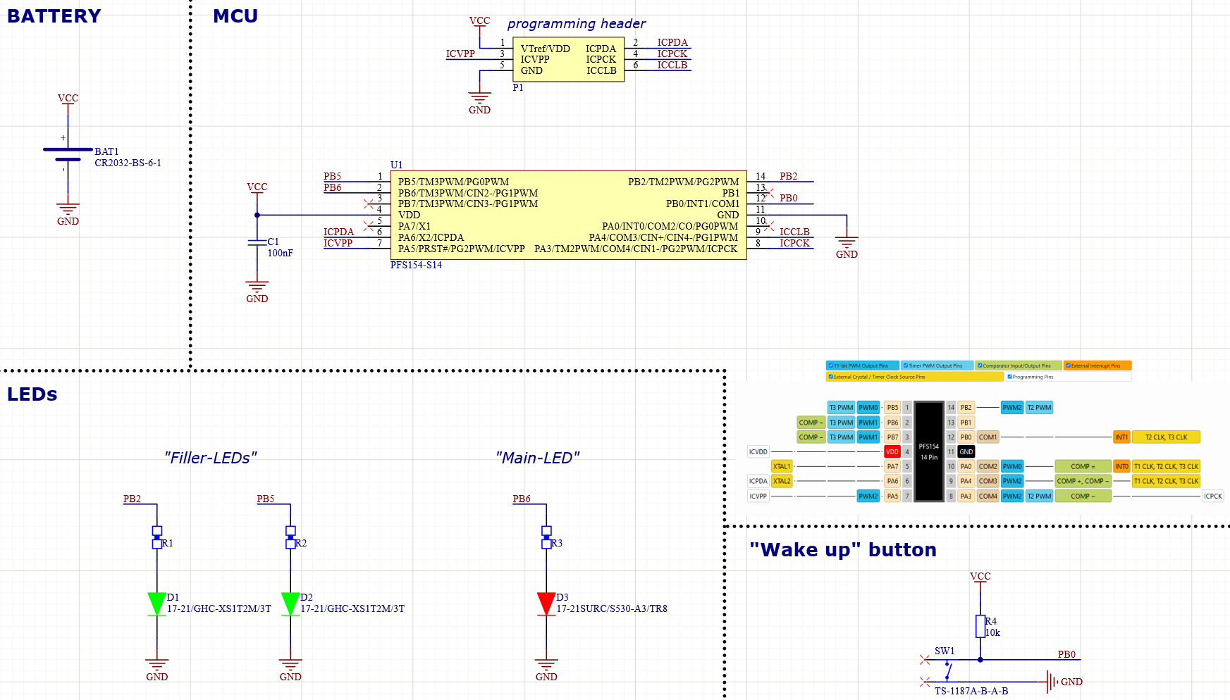
In the 2022 Christmas card is the system directly powered by the battery.
This battery voltage drops through usage, and we will mainly notice this by weaker LED intensities.
How can we do this?
But the LEDs are all PWM controlled!
PWMG2DTL = 0xFF & (intensity << 5);          // lower duty (the 3 lowest)
PWMG2DTH = 0xFF & (intensity >> 3);          // upper duty
And by using the internal comparator (here in the Padauk PFS154 it has only 16 levels) between the input voltage and the internal 1.2V BANDGAP we can get out an approximate level of the voltage we send to the LEDs. The comparator was launched occasionally, and looks like this:
// returns estimated vdd-dV
uint8_t comparator_find_vdd(void)
{

    // setup (and enabling of) COMPARATOR: IN- = VBandGap, IN+ = VInt (selected by GPCS)
    GPCC = (uint8_t) GPCC_COMP_ENABLE | (uint8_t) GPCC_COMP_MINUS_BANDGAP_1V2 | (uint8_t) GPCC_COMP_PLUS_VINT_R;

    for (uint8_t d = 200; d > 0; d--);                  // small delay after GPCC setup required

    uint8_t n = 0;

    // start searching from the bottom. If change, return value from list (average between the change-level and the prev)
    for (n = 0; n < 16; n++)                            // loop over all 16 values of the VInt_R resistor ladder
    {
        GPCS = GPCS_COMP_RANGE1 | ( 15 - n );           // case 1

        for (uint8_t d = 200; d > 0; d--);              // small delay after GPCS setup required

        if ( ! (GPCC & GPCC_COMP_RESULT_POSITIVE) )     // test if comparator result is positive and break if so!
        {
            break;
        }

    }

    // turn off the COMPARATOR
    GPCC = 0;

    // output the corresponding VDD value (we use a string table to avoid printf)
    return vdd_levels[n];
}
This information can was further used to change the LED PWM values, and in the 2022 Christmas card was it done like this:
if ( vdd >= 28 )        { MAIN_LED_MIN = 12;   FILLER_LED_MIN = 1;   }
else if ( vdd >= 27 )   { MAIN_LED_MIN = 23;   FILLER_LED_MIN = 4;   }
else if ( vdd >= 25 )   { MAIN_LED_MIN = 35;   FILLER_LED_MIN = 8;   }
else if ( vdd >= 23 )   { MAIN_LED_MIN = 50;   FILLER_LED_MIN = 25;  }
else if ( vdd >= 22 )   { MAIN_LED_MIN = 60;   FILLER_LED_MIN = 35;  }
else if ( vdd >= 21 )   { MAIN_LED_MIN = 100;  FILLER_LED_MIN = 100; }
else                    { MAIN_LED_MIN = 127;  FILLER_LED_MIN = 127; }
=> We adjust the LED-PWM-levels based on the input voltage, because we know that the LEDs light up weaker when applying a lower voltage
Final thoughts
This does not necessarily extend the total system time, but rather it extends the total “successful” working time 🙂
So think about implementing something like this the next time you make a system where the input voltage might vary.