Breadboard is an essential tool for every electronics engineer and maker. In this blog post we’ll talk about why we use breadboards and how they work.
What?
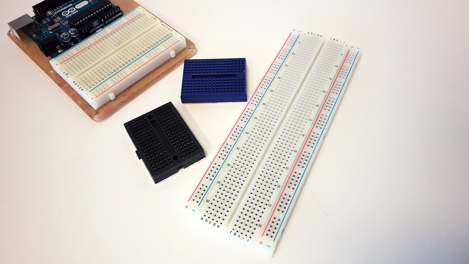
A breadboard is a simple tool which is used to easily connect electrical components and wires together. Only certain component types and wires is applicable for breadboard usage. As long as the components have through-hole pins (as opposed to surface mount), they are probably applicable for breadboards.
Components and wires are attached to the breadboard by simply pressing the pins down into the holes of the breadboard.
Why?
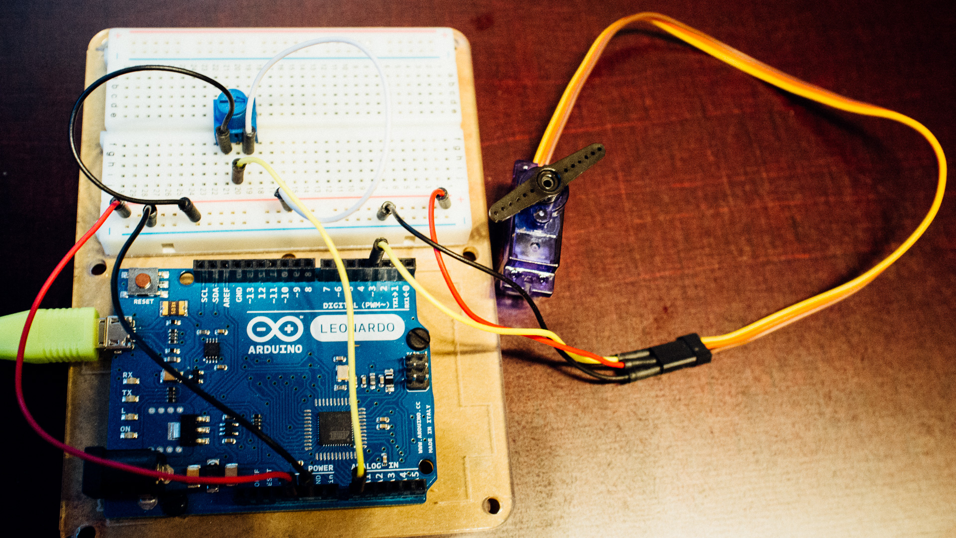
Electronic products almost always have PCBs (printed circuit boards) on the inside. These need to be designed, manufactured and soldered, which isn’t exactly done in a jiffy. Sometimes you need to hook up some electrical components for your prototype when you either don’t have time, interest or knowledge to acquire a PCB. If you just want test a potentiometer, you probably wouldn’t produce a PCB for that sole purpose.
In these cases the breadboard might be the perfect solution. With breadboards you can quickly connect simple electronic circuits and test them out.
Breadboards are however not suitable as permanent circuits inside products and installations. In those instances a more “soldery” and failure-safe solution should be used.
How?
To use a breadboard you just push the pins on either electrical through-hole components or jumper wires into the holes. The holes have springs in them to keep the components from falling out. The trick, however, is to put the pins into the right holes such that you get the circuit you want.
Some of the holes in breadboards are connected together and it’s important to know which. In the image below you can see how this is typically done.
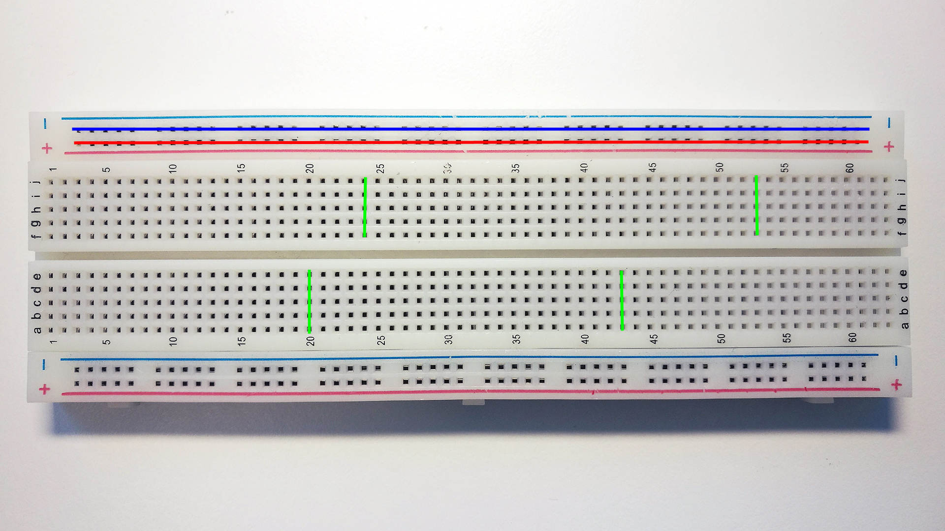
The red and blue holes are typically used as Vcc (e.g. +5V) and GND, respectively. Since many components often need connection to both of these lines, one can easily hook up to this “rail” wherever you want. The cravas along the center of breadboards like the one in the image above separates the connectivity between the green holes in the center.
If you’re unsure of how the holes in your breadboard is connected together, check it by using a digital multimeter.
Alternatives to Breadboards
There are a few alternatives to breadboards which require soldering. Two of them are veroboards and protoboards.
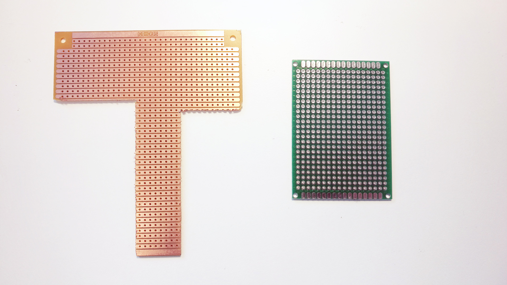
The most similar to breadboard is the veroboard. This board consists of a matrix of holes that are connected together along a single axis. The protoboards have the same type of holes except that none of the holes are connected.
Concluding Words
Breadboards are very nice for what they do, but isn’t useful in every scenario.
We might revisit the breadboard topic in the future to check how much current it can handle and other fun stuff, so (as always) stay tuned!