A long time ago we repaired a rather common problem on a NAD C370 amplifier: Namely the “slow start circuit”. And the fix worked great (and it still works)!
But now, over 2 years later, the amplifier is back with a new challenge. But what?
In this post we will show you how we searched for the problem, how we fixed it, and in the end: final testing / did it work?
The Problem
The challenge with the unit was that it didn’t turn on. Was it just the control logic that was broken or something more of the “deeper amplifier magic”?
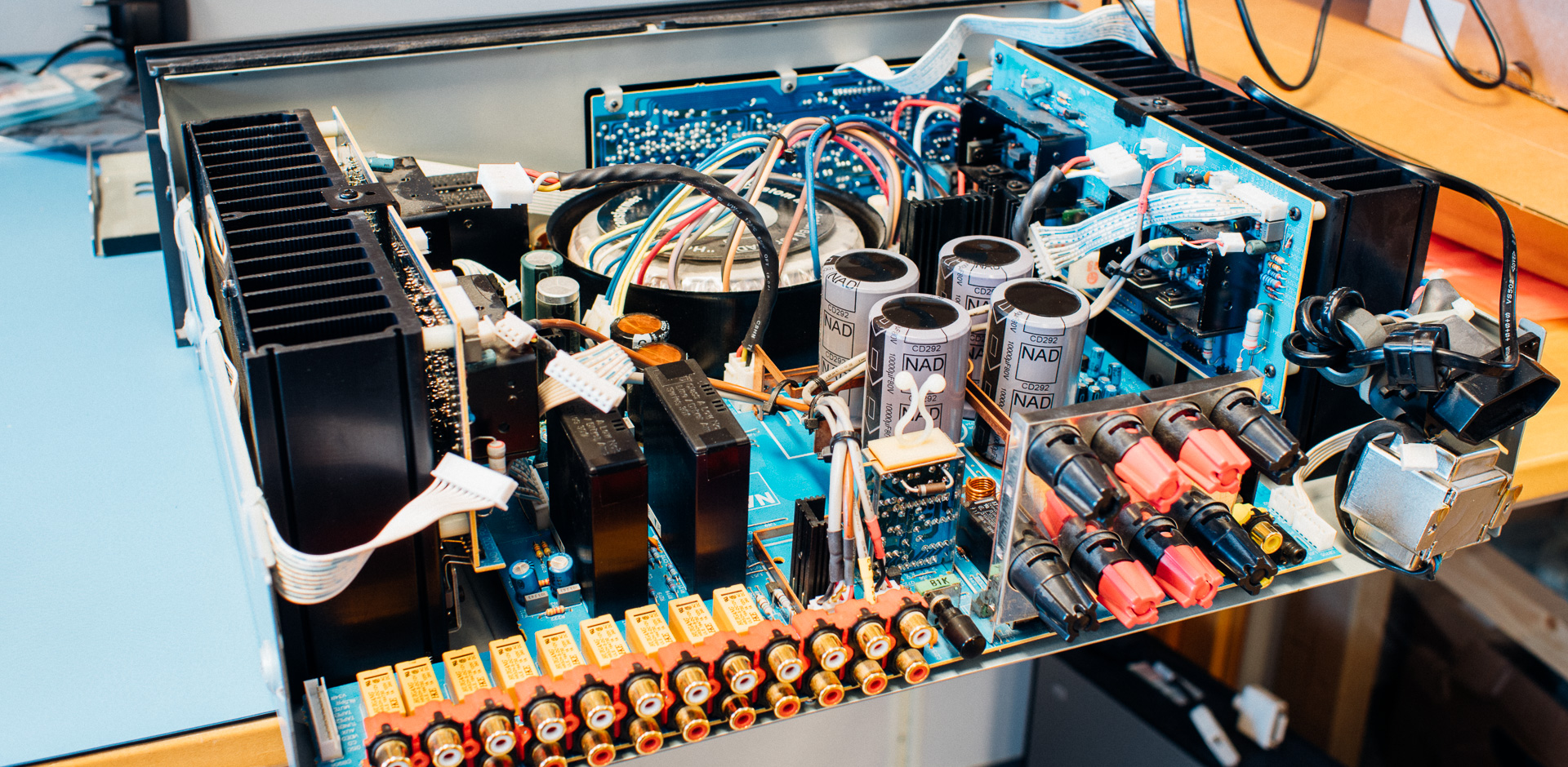
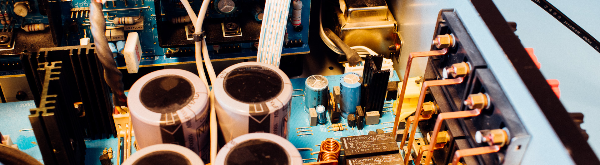
To find out that, we opened the unit and started with maybe the most basic step in embedded system troubleshooting: Namely power-rail testing.
And lo and behold, the 5 V power rail was not exactly pretty!
The unit consists of several components, but the two most relevant here can we call: “The Main Board” and “The Front Panel”.
The Main Board
The Main Board ties everything together and this is were most of “the Magic” happens. This is, among other things, where the “slow start circuit” (which was repaired earlier) resides.
Whats interesting here is that it has all the circuit for generating the 5 volt rail.
The Front Panel
The Front Panel is responsible for gathering user commands through either IR (from the remote) or through button presses and/or volume pot adjustments.
Whats worth noting here is that it is gets all necessary power rails from the Main Board.
Troubleshooting
1) Finding the error
As stated earlier we started with measuring the power rails and discovered problems on the 5 volt rail.
We continued down this path, and the next step was to discover if the problem resided on the source- (the 5V regulator circuit) or the sink-side (the Front panel).
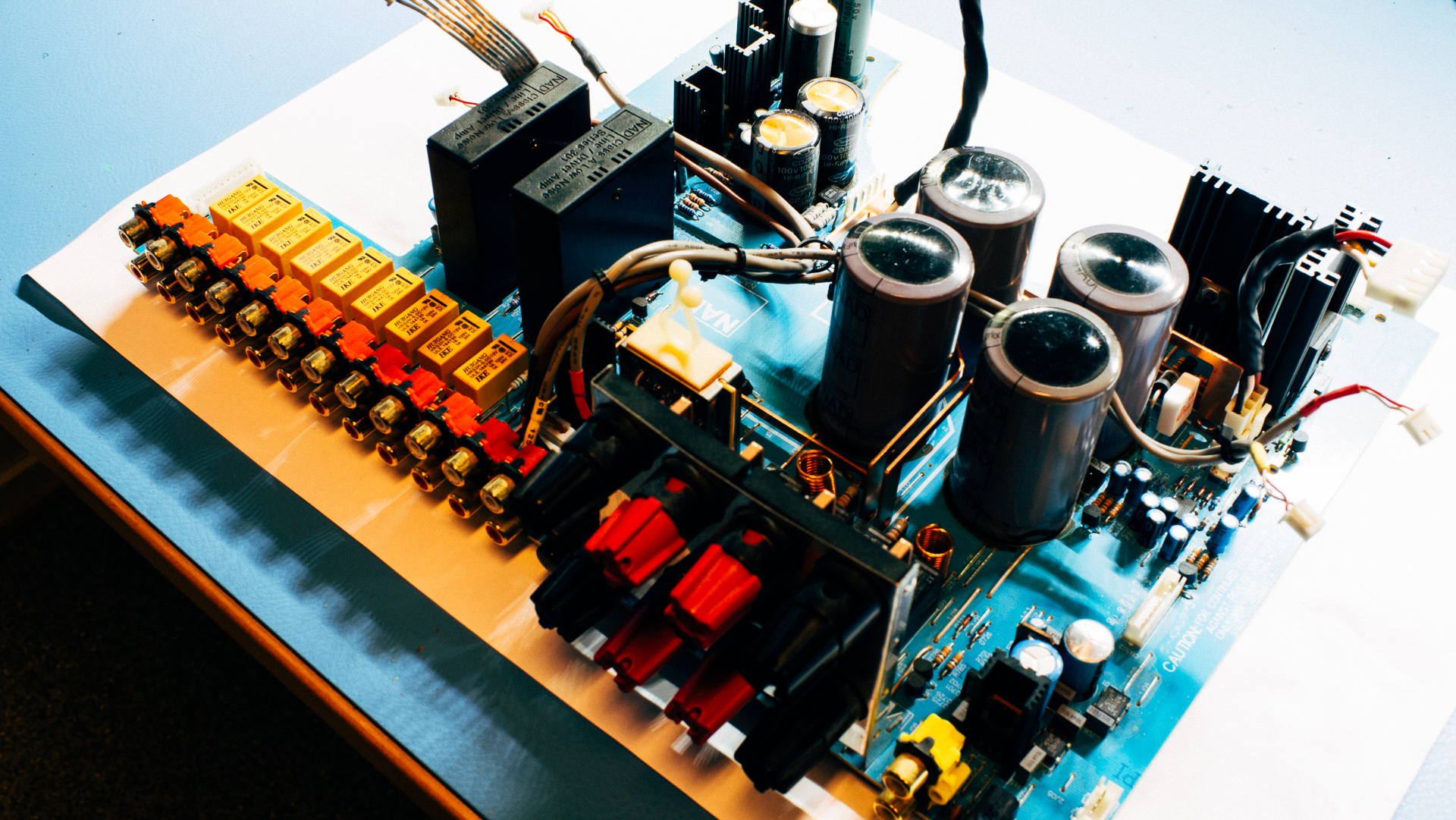
To do this we separated the boards and powered up the Main Board. The 5 v coming out from the Main Board looked much better (wo. load), but still not 100%.
To find out if the Front panel had internal problems we fed it with an external 5 volt and it worked perfectly!
=> So we concluded that this problem was with the 5 volt supply on the Main Board.
2) Proposed solution
After discovering that this problem was with the 5 volt supply circuit on the main board, combined with the age of this product, we decided to replace components.
3) Gathering supplies
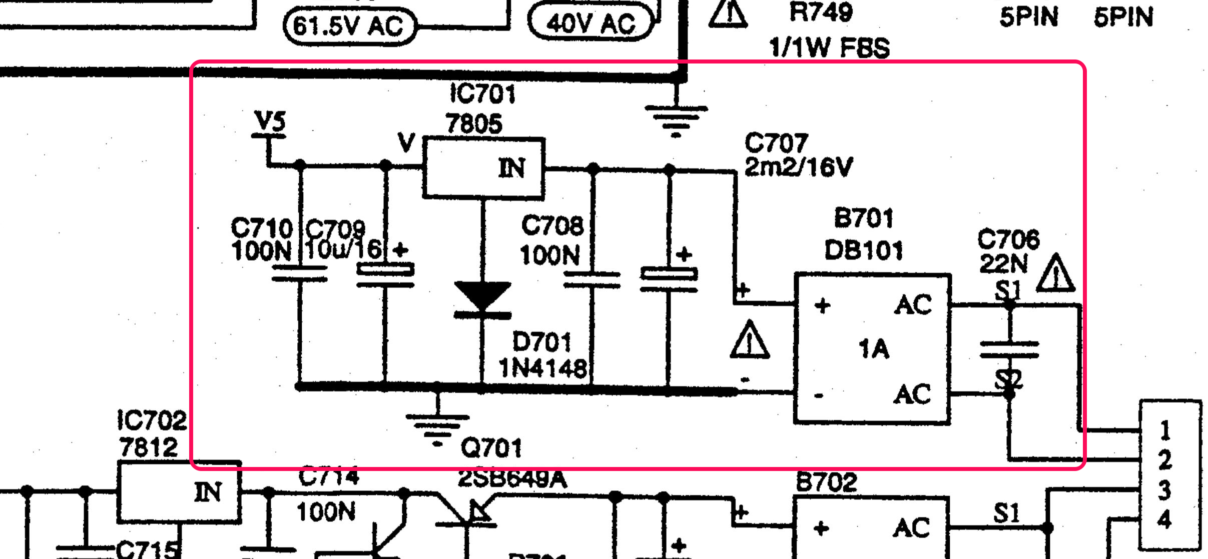
The first thing you should get hold of is diagrams showing the relevant circuit.
For this product it’s rather easy to get your hand on a detailed service manual. After it had been collected, we quickly found the 5 volt circuit on the Main Board and wrote a short list with the parts we wanted to do something with.
So if we just replaced all components residing there we would (hopefully) get rid of the problem.
Replacements where found and added to an order from Digi-Key.
4) Implementing the proposed solution
Remember that a product like this probably is soldered using lead, so you have to take care not contaminating the equipment you use for lead-free soldering 🙂
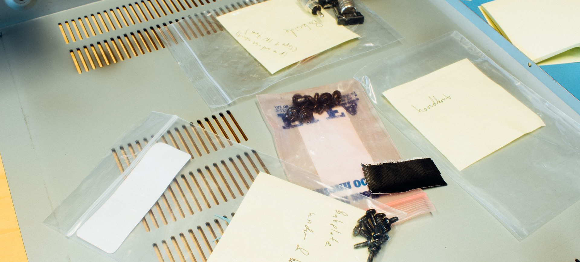
After all the replacement part where received, we disassembled the unit and made it ready for part replacement.
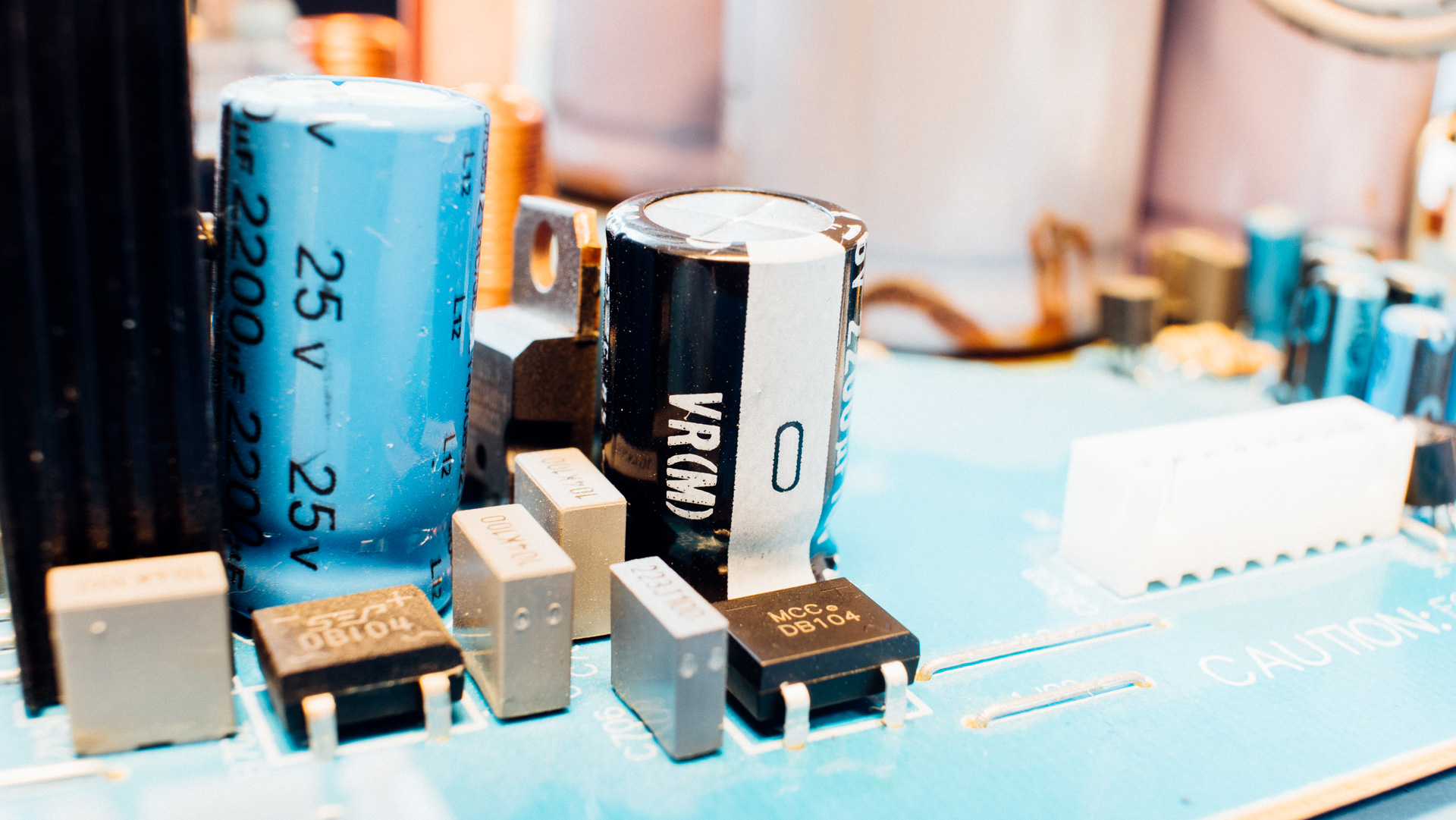
We started with replacing B701, and after that we replaced C707. The plan was to continue replacing all the parts, but we stopped because C707 was suspiciously bad looking.
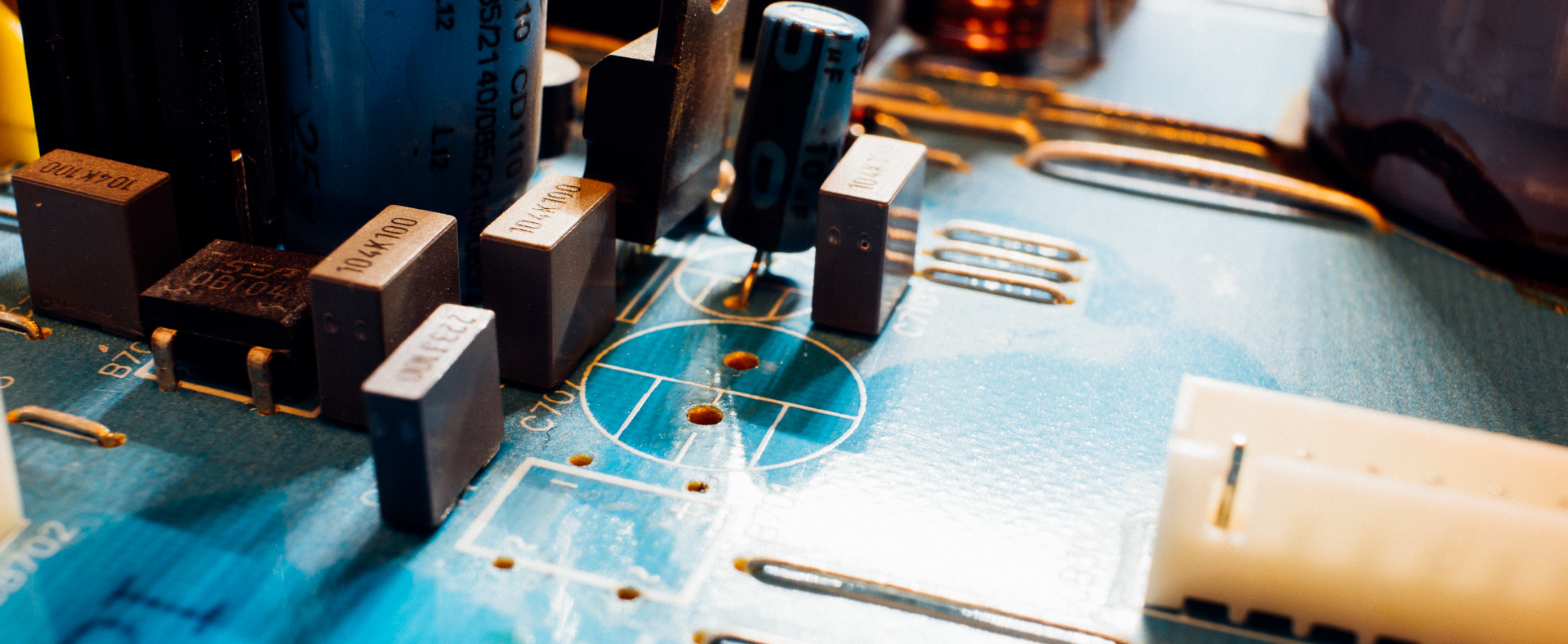
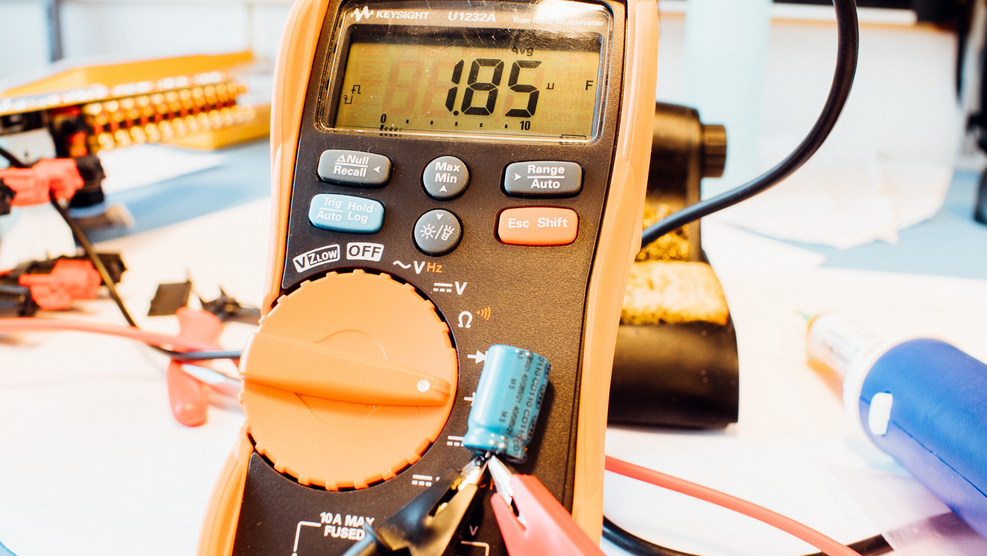
We did a quick capacitor value measuring using a multimeter. It is not that accurate, but it might give you an indication.
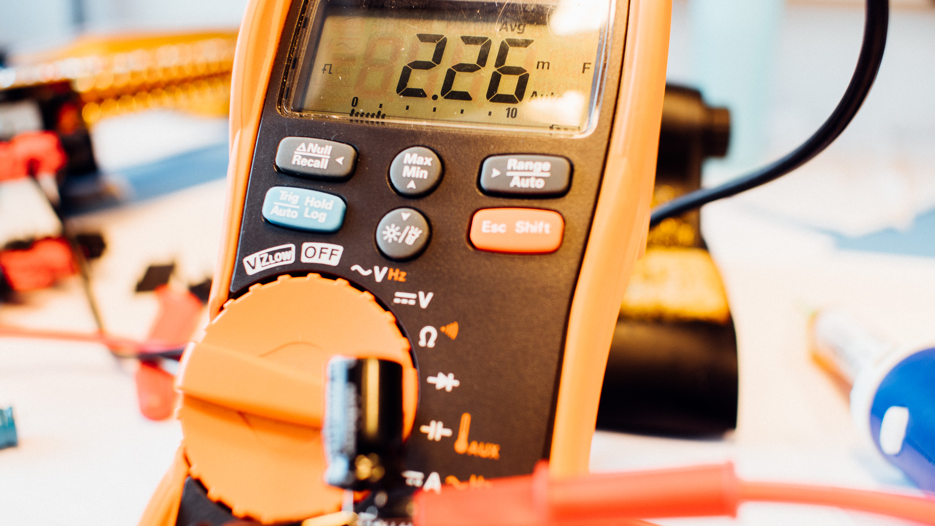
We also meassured the replacement part:
Final testing and thoughts
After this discovery we where quite confident that the problem was caused by a faulty C707. So after it was replaced we assembled the necessary parts to do a quick test.
It worked 🙂
We put everything together again. And whats left to do now is a long-term test of the unit. But it is looking good so far.
As shown here it was just one(!) component that made this product not work. And by (a rather simple) fix we gave this unit many more happy years to live.
If you have not read it, we highly recommend “The Repair Manifesto by IFIXIT“