A common challenge is how you can go from a free hand drawing to a more technical correct illustration.
In this blog post we are going to show you a process you can use to go from a simple hand drawn “2D”-form to a 3D-print by using Fusion 360.
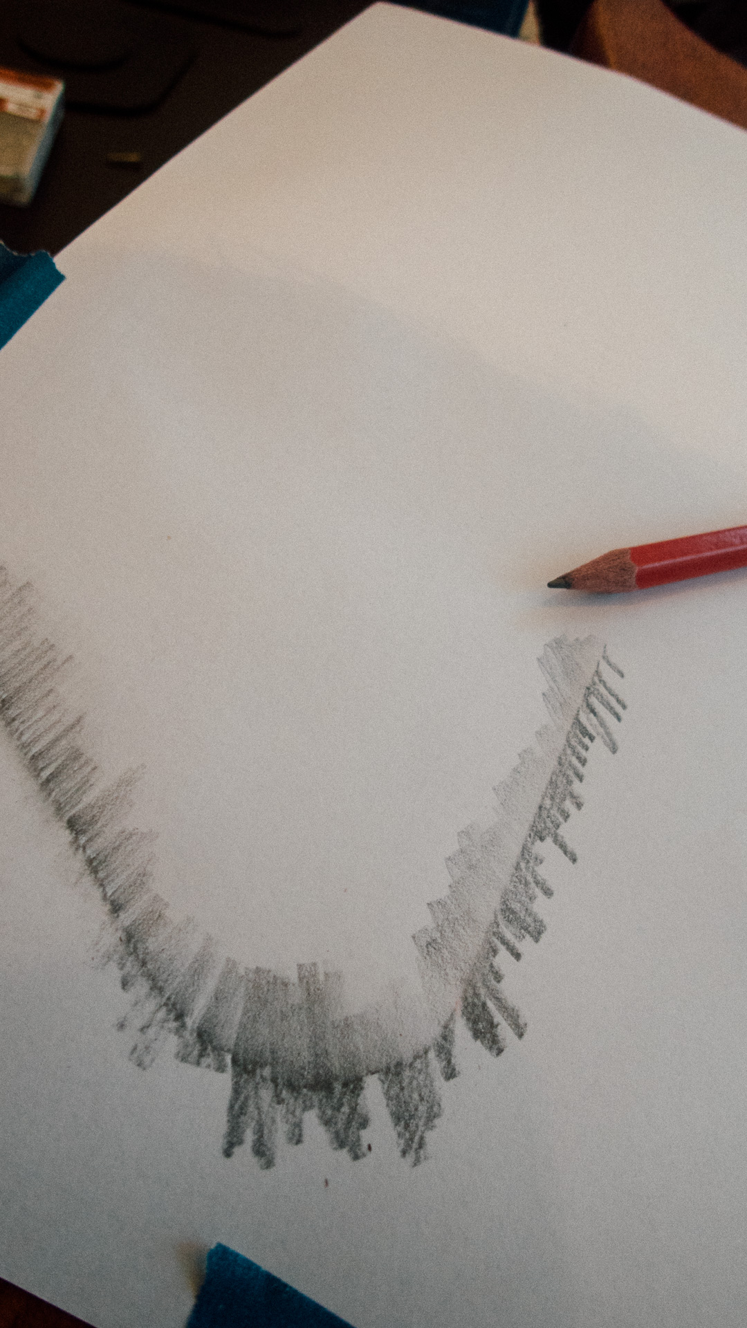
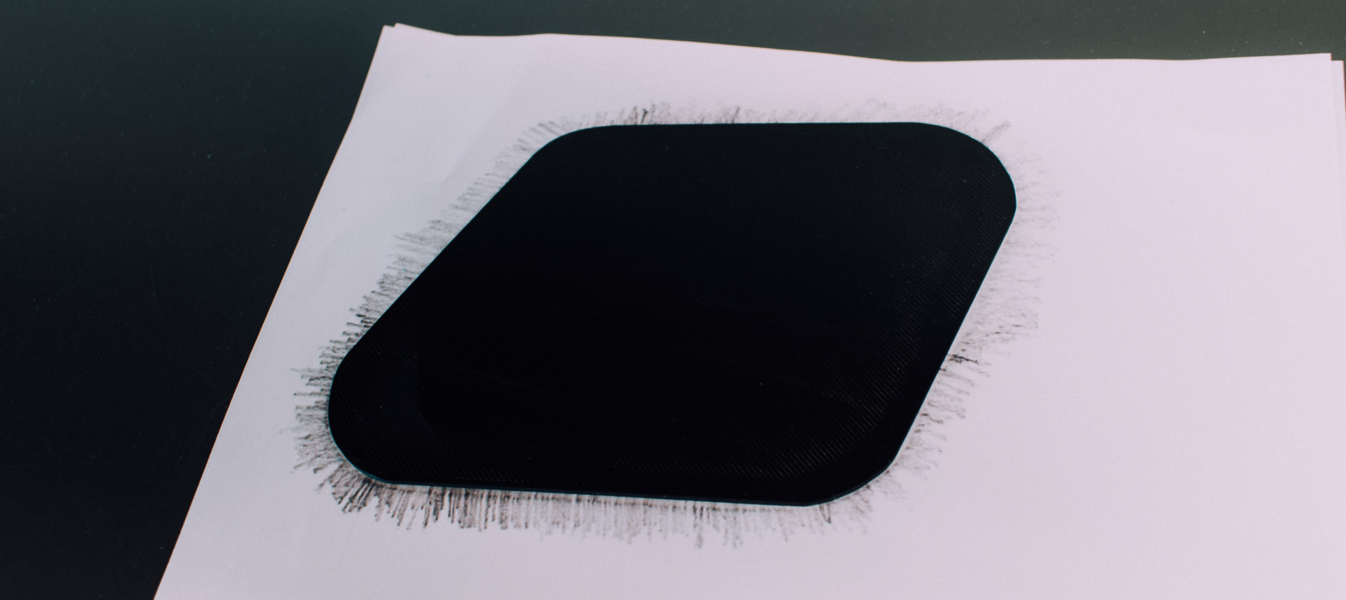
Making a free hand drawing
We start in this blogpost with something rather simple:
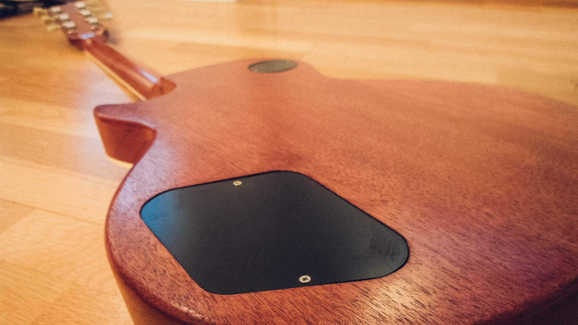
Backplates for an electrical guitar
The guitar in question had a custom made body with several irregular forms and we didn’t have any technical drawings.
So we had to make a drawing of what we needed ourself.
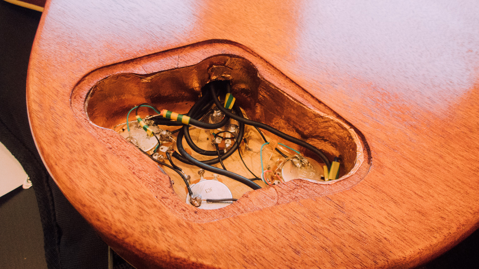
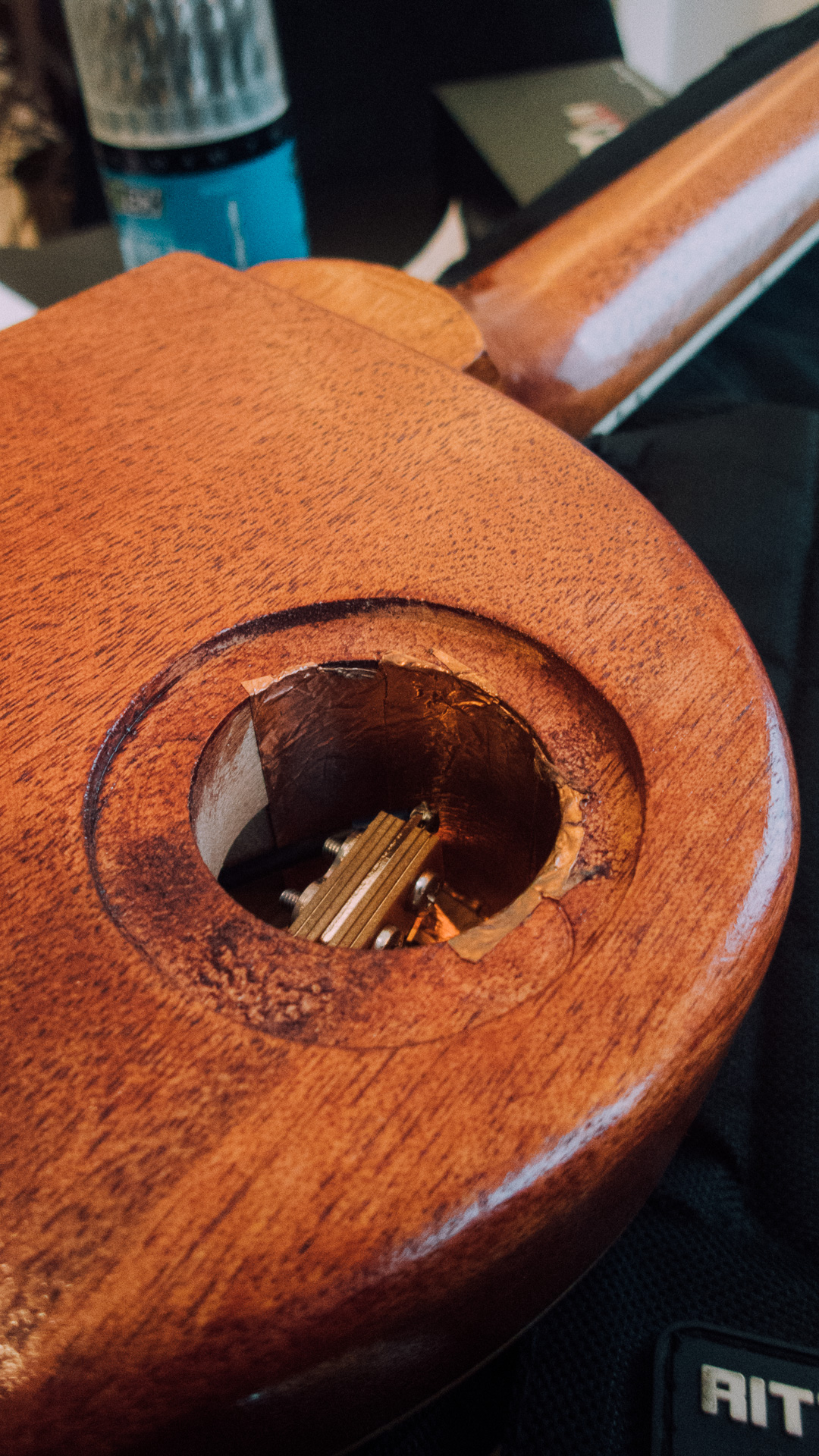
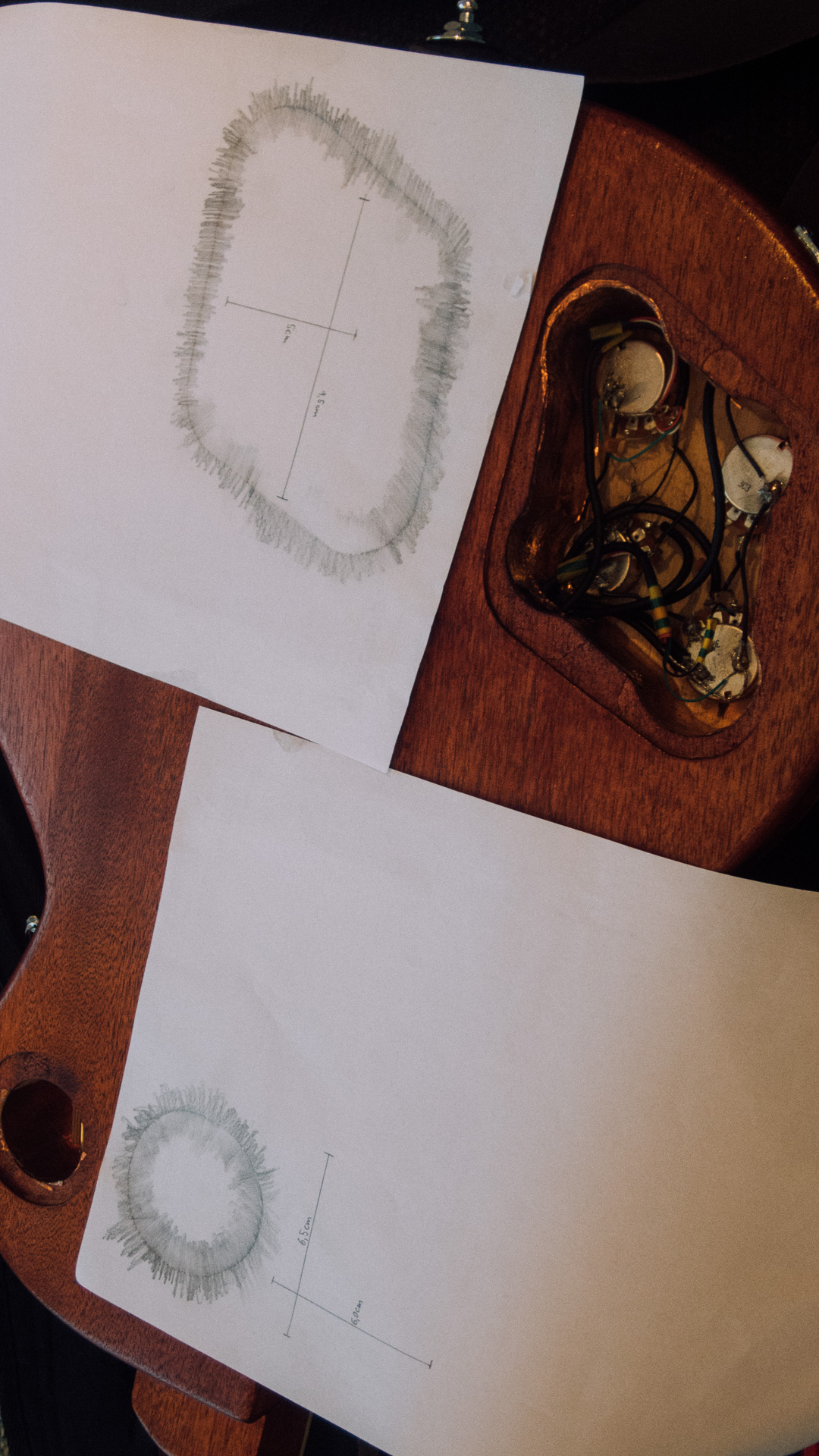
The guitar needed two different backplates, and as you can see does one of the backplates look rather circular, but it was not a perfect circle. Nor was the other backplate perfectly symmetrical.
Simple measurement and technical re-creation had been a rather comprehensive job in this situation.
So we decided to copy the whole form and do the measurement on the digitised drawing.
Making a technical drawing
With drawings made (including scales) and scanned we was ready to make a “technical correct illustration”.
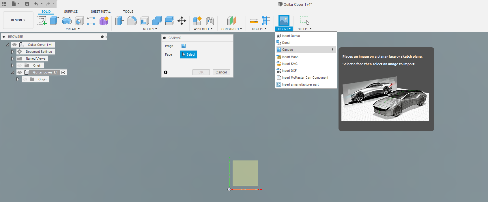
To do this we used Autodesk Fusion 360. We started with importing the drawing:
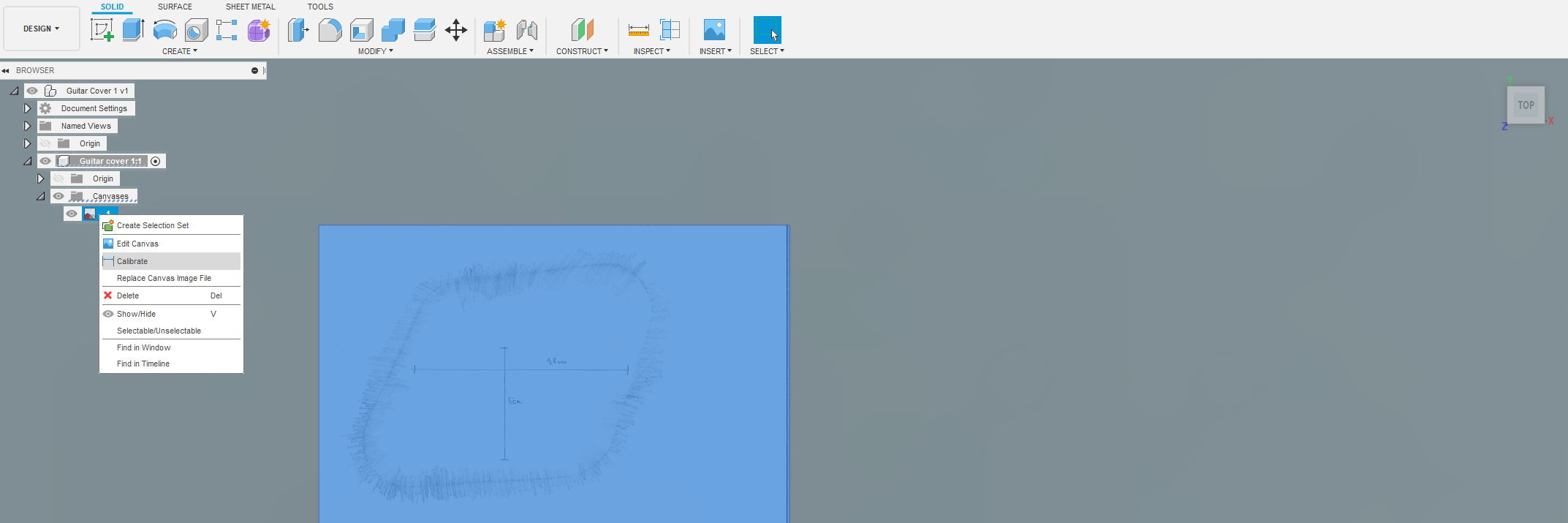
After the image was inserted we had to calibrate it to match the correct “real life” dimensions. This was done by left clicking on the inserted canvas and selecting “Calibrate“.
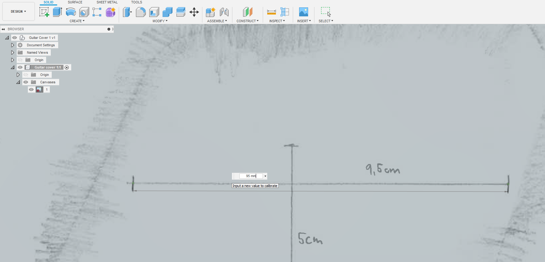
To calibrate the drawing we selected two points on the canvas and inserted how long it should be between them.
Note here that this assumes that the canvas are scaled equal in all axes. You can of course scale the image different in the different axis, but here all axes scale were the same.
A helpful tool here was scanning. This did not add any vertical transformation, making the X and Y axis equally scaled.
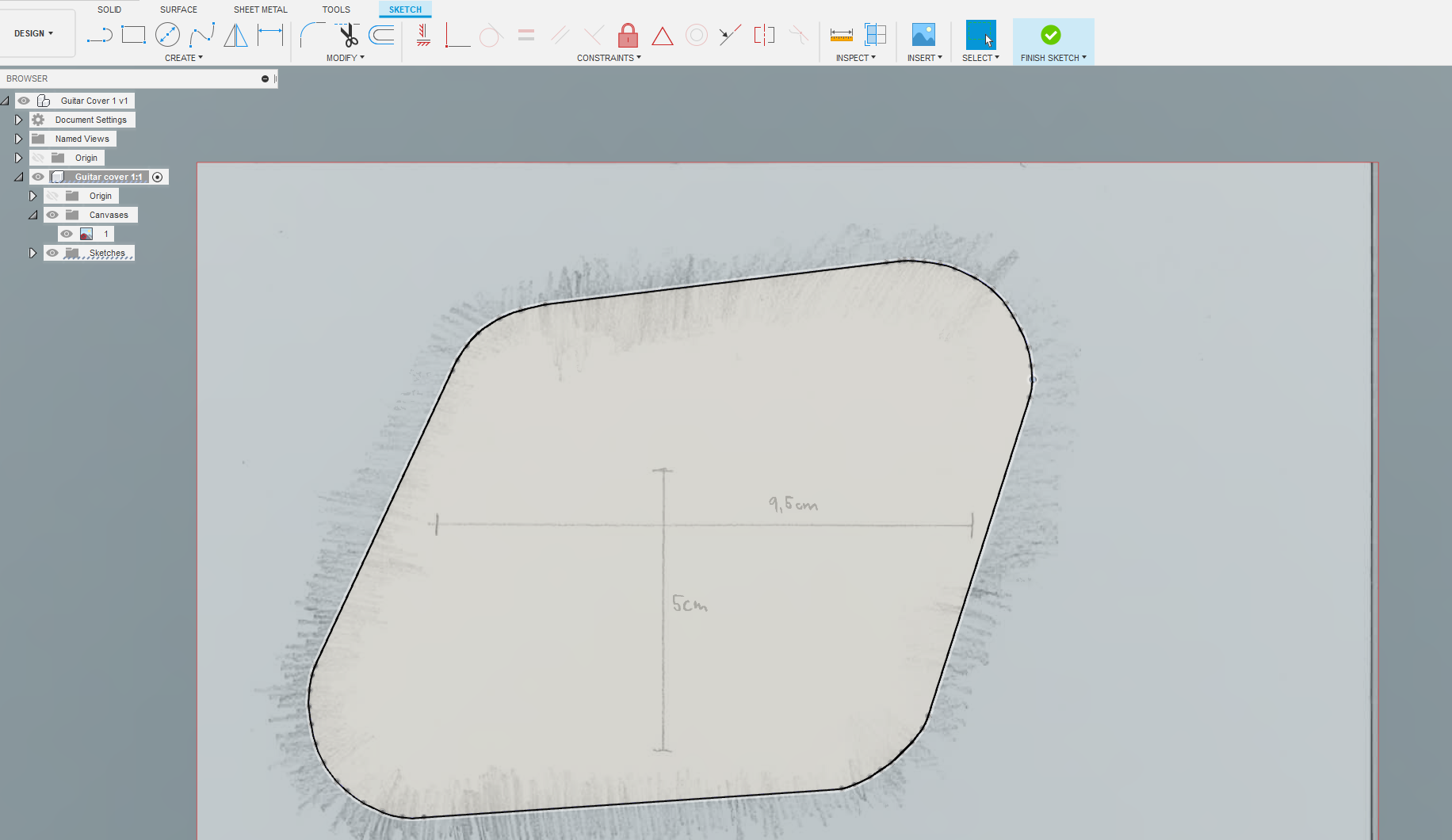
After the canvas was Calibrated it was manually traced in a sketch:
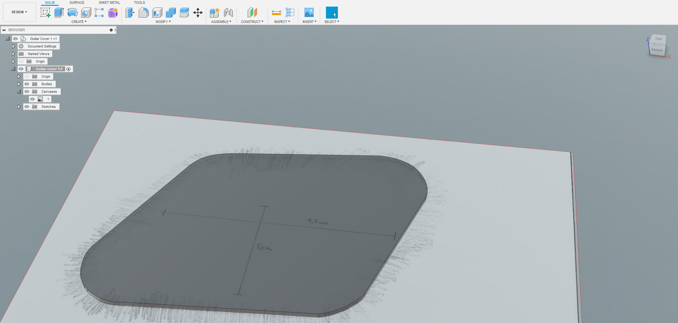
The sketch was then extruded to a solid body:
3D-printing
To be sure that it would fit nicely on the guitar body, we added 0.5 mm clearance (offset from the drawing) and then we extruded 1.5 mm thick backplates.
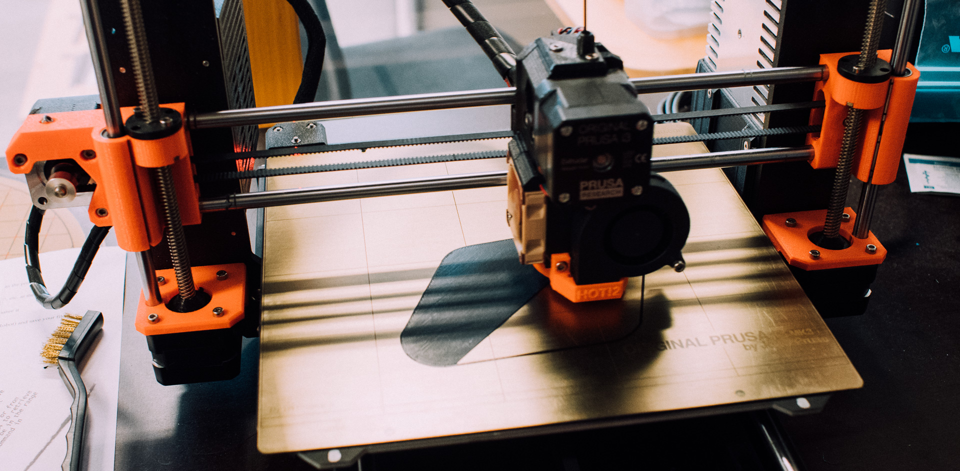
Thereafter we 3D-printed them with 100% infill and black PLA.
Final results
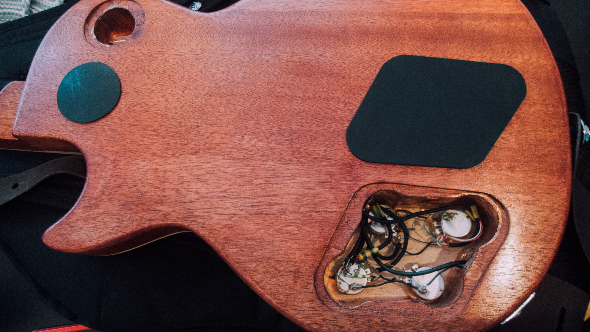
As you probably noticed in the models; they did not include any mounting holes.
But that was intentional!
We did not know how the backplates was going to be attached to the guitar, nor did we know where to place them (if attachment was to be done with screws). So we decided to wait to after 3D-printing with finding out how the plates where going to be attached to the guitar body.
As you can see we ended up with drilling holes in both the 3D-printed backplates and the guitar after 3D-printing.
A recap of the process:
- Manually draw the form(s). Important: Include the scales in the drawing.
- Digitise the drawing(s). We used a photo scanner. That guaranteed Y and X scaling similarity compared to digital photography.
- Import, calibrate and make a technical correct illustration.
- Prepare the drawing for Creation. (Here: 3D-print)
- Make the parts and assemble them.
- Enjoy the result!