Previous parts in this series:
In this post we’ll look at the electronics and the code and libraries used to control the vehicle.
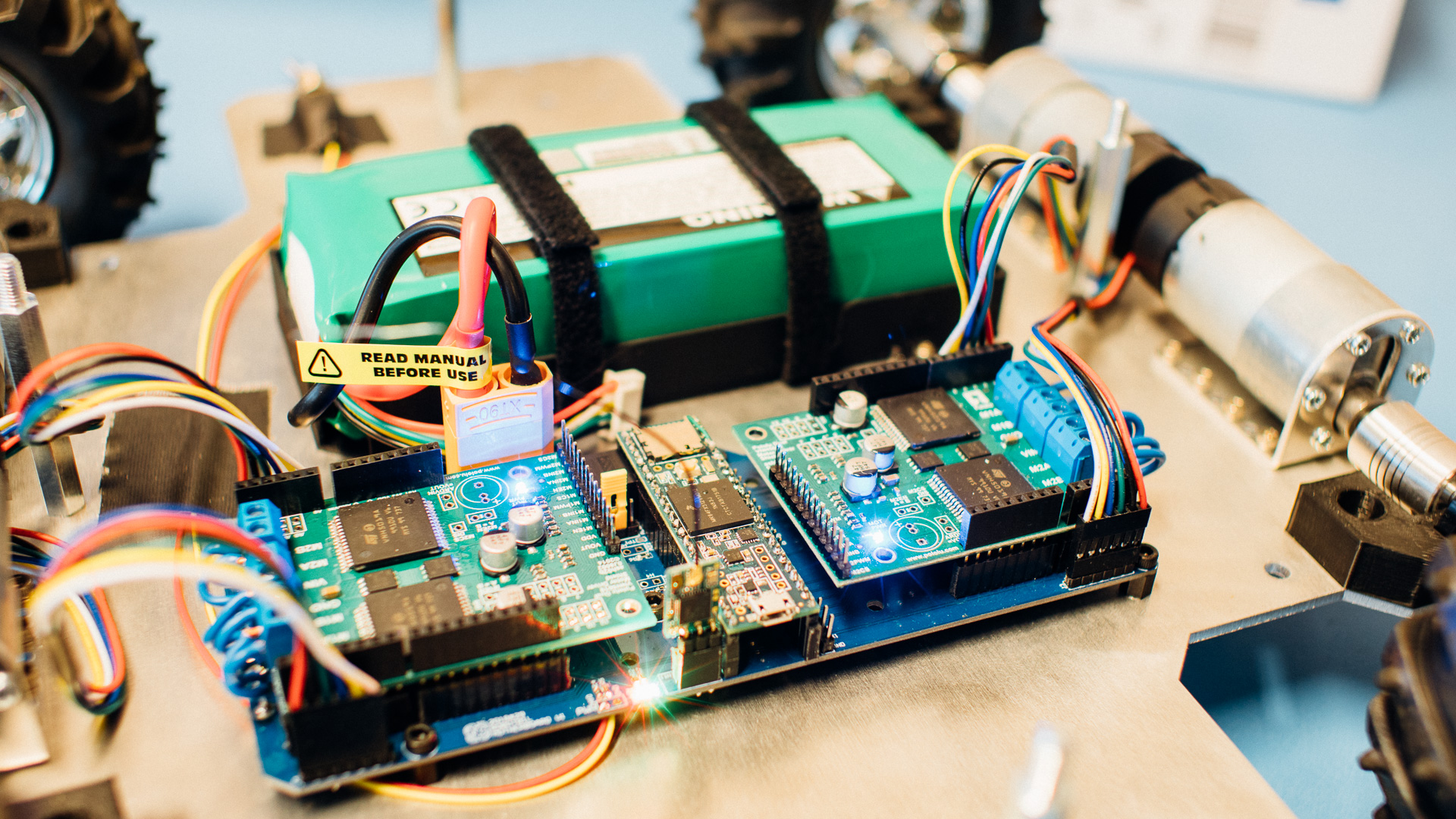
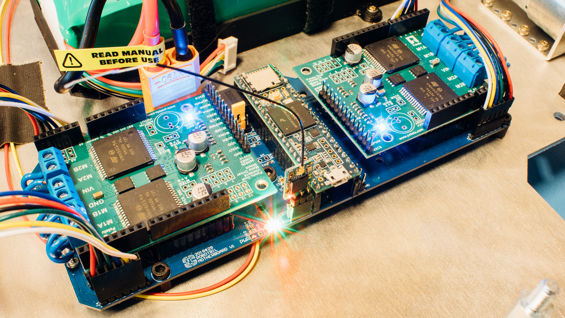
Motherboard PCB
To tie the motorcontrollers, Teensy and receiver together, we chose to design our own motherboard. This PCB also includes a voltage regulator for the 5V logic voltage in addition to various communication headers (UART, SPI, I2C) and an XT90 port for the battery plug. And some LEDs, of course.
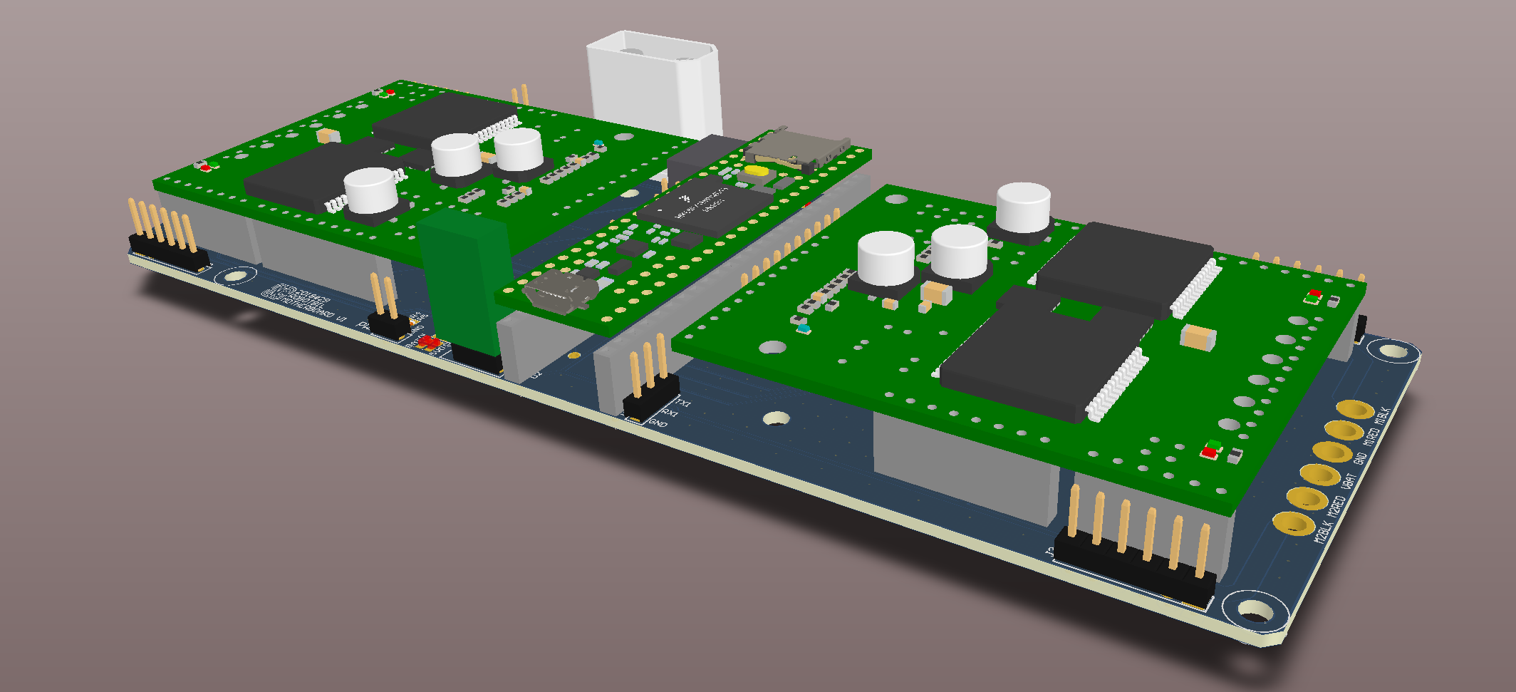
We’ve also soldered a power switch to the PCB to turn on and off the power.
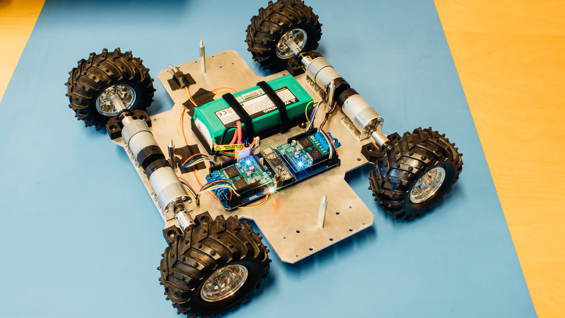
The motherboard is mounted to the base plate with nylon spacers.
Battery Holder
We printed a battery holder for the 14.8 V 10000 mAh battery. This is a very basic part where we just insert the battery and fasten it with Velcro ties. The holder part is bolted down to the base plate. Simple stuff!
Firmware
The Teensy 3.5 code is written using Teensyduino, which lets us using Arduino libraries.
Functionality
The current vehicle functionality is that we use our FrSky Taranis Q X7 to manually control the vehicle.
Code-wise we continuously read a few channels from the radio receiver. Through a quick algorithm we find the desired speed on the right wheels and the left wheels.
Each motor has two encoder channels, and each time any of these channels goes from low to high (or vice versa), an appropriate interrupt service routine is called to keep track of how far each wheel has turned for each main loop cycle. We use this information in a simple P-regulator to brake the wheels that turn too fast.
Without this functionality the turning behavior was undesirable, where the turning sensitivity was too low until the target direction of the inner wheels was opposite of the traveling direction. With the active braking functionality the turning is much more smooth. Right now we use one of the toggle switches to turn on and off this functionality.

Libraries
We’re using two 3rd party libraries to get things up and running quickly:
- SBUS – this library makes it easy to handle radio inputs.
- dual-vnh5019-motor-shield – this library provides an easy interface to the motor controllers.
Code
#include <DualVNH5019MotorShield.h>
#include <SBUS.h>

#define NUM_CHANNELS 16
#define TICKS_PER_ROTATION 64
#define LOOP_INTERVAL_MS 20
#define MAX_PWM 400
#define PWM_LIMIT 324 //limit for 14.8V battery -> 12V rated motors
#define MIN_SPEED_THRESHOLD 15
#define DEBUG_GAIN 0.1
#define BRAKE_GAIN 7

//Motor pins

const uint8_t M1_INA = 2;
const uint8_t M1_INB = 3;
const uint8_t M1_PWM = 29;
const uint8_t M1_EN_DIAG = 6;
const uint8_t M1_CS = 31;
const uint8_t M1_ENC_A = 24;
const uint8_t M1_ENC_B = 25;

const uint8_t M2_INA = 4;
const uint8_t M2_INB = 5;
const uint8_t M2_PWM = 30;
const uint8_t M2_EN_DIAG = 9;
const uint8_t M2_CS = 32;
const uint8_t M2_ENC_A = 26;
const uint8_t M2_ENC_B = 27;

const uint8_t M3_INA = 23;
const uint8_t M3_INB = 22;
const uint8_t M3_PWM = 14;
const uint8_t M3_EN_DIAG = 19;
const uint8_t M3_CS = 34;
const uint8_t M3_ENC_A = 17;
const uint8_t M3_ENC_B = 16;

const uint8_t M4_INA = 21;
const uint8_t M4_INB = 20;
const uint8_t M4_PWM = 35;
const uint8_t M4_EN_DIAG = 18;
const uint8_t M4_CS = 33;
const uint8_t M4_ENC_A = 39;
const uint8_t M4_ENC_B = 36;

//Global variables

float channels[NUM_CHANNELS];
bool failSafe;
bool lostFrames;

float left_gain = 0.0;
float right_gain = 0.0;
float factor = 0.0;

int previous_error_1 = 0;
int previous_error_2 = 0;
int previous_error_3 = 0;
int previous_error_4 = 0;

unsigned int enc_1a_ticks = 0;
unsigned int enc_1b_ticks = 0;
unsigned int enc_2a_ticks = 0;
unsigned int enc_2b_ticks = 0;
unsigned int enc_3a_ticks = 0;
unsigned int enc_3b_ticks = 0;
unsigned int enc_4a_ticks = 0;
unsigned int enc_4b_ticks = 0;

unsigned int enc_1_ticks = 0;
unsigned int enc_2_ticks = 0;
unsigned int enc_3_ticks = 0;
unsigned int enc_4_ticks = 0;

unsigned int enc_1_filtered = 0;
unsigned int enc_2_filtered = 0;
unsigned int enc_3_filtered = 0;
unsigned int enc_4_filtered = 0;

int enc_1_mapped = 0;
int enc_2_mapped = 0;
int enc_3_mapped = 0;
int enc_4_mapped = 0;

uint8_t dir_1 = 0;
uint8_t dir_2 = 0;
uint8_t dir_3 = 0;
uint8_t dir_4 = 0;

int brake_1 = 0;
int brake_2 = 0;
int brake_3 = 0;
int brake_4 = 0;

unsigned long time_now = 0;

DualVNH5019MotorShield ms1(M1_INA, M1_INB, M1_PWM, M1_EN_DIAG, M1_CS, M2_INA, M2_INB, M2_PWM, M2_EN_DIAG, M2_CS);
DualVNH5019MotorShield ms2(M3_INA, M3_INB, M3_PWM, M3_EN_DIAG, M3_CS, M4_INA, M4_INB, M4_PWM, M4_EN_DIAG, M4_CS);

SBUS x8r(Serial6);

void setup() {
  ms1.init();
  ms2.init();

  x8r.begin();

  //Serial1.begin(115200);

  pinMode(M1_ENC_A, INPUT);
  pinMode(M1_ENC_B, INPUT);
  pinMode(M2_ENC_A, INPUT);
  pinMode(M2_ENC_B, INPUT);
  pinMode(M3_ENC_A, INPUT);
  pinMode(M3_ENC_B, INPUT);
  pinMode(M4_ENC_A, INPUT);
  pinMode(M4_ENC_B, INPUT);

  attachInterrupt(digitalPinToInterrupt(M1_ENC_A), ENC_1A_ISR, CHANGE);
  attachInterrupt(digitalPinToInterrupt(M1_ENC_B), ENC_1B_ISR, CHANGE);
  attachInterrupt(digitalPinToInterrupt(M2_ENC_A), ENC_2A_ISR, CHANGE);
  attachInterrupt(digitalPinToInterrupt(M2_ENC_B), ENC_2B_ISR, CHANGE);
  attachInterrupt(digitalPinToInterrupt(M3_ENC_A), ENC_3A_ISR, CHANGE);
  attachInterrupt(digitalPinToInterrupt(M3_ENC_B), ENC_3B_ISR, CHANGE);
  attachInterrupt(digitalPinToInterrupt(M4_ENC_A), ENC_4A_ISR, CHANGE);
  attachInterrupt(digitalPinToInterrupt(M4_ENC_B), ENC_4B_ISR, CHANGE);
}

void loop() {
  time_now = millis();

  int setpoint_right = 0;
  int setpoint_left = 0;

  if(x8r.readCal(&channels[0], &failSafe, &lostFrames)){
	if(abs(channels[7]) > 0.1){
	  right_gain = DEBUG_GAIN;
	  left_gain = DEBUG_GAIN;
	}
	else{
	  left_gain = channels[2] + channels[1];  //throttle + turn
	  right_gain = channels[2] - channels[1]; //throttle - turn

	  if(left_gain > 1.0){
		factor = 1.0/left_gain;
		left_gain = 1.0;
		right_gain = factor*right_gain;
	  }
	  else if(right_gain > 1.0){
		factor = 1.0/right_gain;
		right_gain = 1.0;
		left_gain = factor*left_gain;
	  }
	  else if(left_gain < -1.0){
		factor = -1.0/left_gain;
		left_gain = -1.0;
		right_gain = factor*right_gain;
	  }
	  else if(right_gain < -1.0){
		factor = -1.0/right_gain;
		right_gain = -1.0;
		left_gain = factor*left_gain;
	  }
	}
  }

  setpoint_right = round(right_gain*PWM_LIMIT);
  setpoint_left = round(-left_gain*PWM_LIMIT);

  enc_1_ticks = enc_1a_ticks + enc_1b_ticks;
  enc_2_ticks = enc_2a_ticks + enc_2b_ticks;
  enc_3_ticks = enc_3a_ticks + enc_3b_ticks;
  enc_4_ticks = enc_4a_ticks + enc_4b_ticks;

  enc_1a_ticks = 0;
  enc_1b_ticks = 0;
  enc_2a_ticks = 0;
  enc_2b_ticks = 0;
  enc_3a_ticks = 0;
  enc_3b_ticks = 0;
  enc_4a_ticks = 0;
  enc_4b_ticks = 0;

  enc_1_mapped = map(enc_1_ticks, 0, 276, 0, PWM_LIMIT);
  enc_2_mapped = map(enc_2_ticks, 0, 276, 0, PWM_LIMIT);
  enc_3_mapped = map(enc_3_ticks, 0, 276, 0, PWM_LIMIT);
  enc_4_mapped = map(enc_4_ticks, 0, 276, 0, PWM_LIMIT);

  if(!dir_1){
	enc_1_mapped = enc_1_mapped*(-1);
  }
  if(!dir_2){
	enc_2_mapped = enc_2_mapped*(-1);
  }
  if(!dir_3){
	enc_3_mapped = enc_3_mapped*(-1);
  }
  if(!dir_4){
	enc_4_mapped = enc_4_mapped*(-1);
  }

  int error_1 = abs(setpoint_right) - abs(enc_1_mapped);
  int error_2 = abs(setpoint_left) - abs(enc_2_mapped);
  int error_3 = abs(setpoint_left) - abs(enc_3_mapped);
  int error_4 = abs(setpoint_right) - abs(enc_4_mapped);

  if(abs(setpoint_right) < MIN_SPEED_THRESHOLD){
	setpoint_right = 0;
  }
  if(abs(setpoint_left) < MIN_SPEED_THRESHOLD){
	setpoint_left = 0;
  }

  if(error_1 < 0 && channels[8] > 0){
	brake_1 = BRAKE_GAIN*error_1;
	if(brake_1 > MAX_PWM){
	  brake_1 = MAX_PWM;
	}
	ms1.setM1Brake(brake_1);
  }
  else{
	ms1.setM1Speed(setpoint_right);
  }

  if(error_2 < 0 && channels[8] > 0){
	brake_2 = BRAKE_GAIN*error_2;
	if(brake_2 > MAX_PWM){
	  brake_2 = MAX_PWM;
	}
	ms1.setM2Brake(brake_2);
  }
  else{
	ms1.setM2Speed(setpoint_left);
  }

  if(error_3 < 0 && channels[8] > 0){
	brake_3 = BRAKE_GAIN*error_3;
	if(brake_3 > MAX_PWM){
	  brake_3 = MAX_PWM;
	}
	ms2.setM1Brake(brake_3);
  }
  else{
	ms2.setM1Speed(setpoint_left);
  }

  if(error_4 < 0 && channels[8] > 0){
	brake_4 = BRAKE_GAIN*error_4;
	if(brake_4 > MAX_PWM){
	  brake_4 = MAX_PWM;
	}
	ms2.setM2Brake(brake_4);
  }
  else{
	ms2.setM2Speed(setpoint_right);
  }

  ms1_stopIfFault();
  ms2_stopIfFault();

  while(millis() < time_now + LOOP_INTERVAL_MS);
}

void ENC_1A_ISR(void){
  enc_1a_ticks++;
  if(digitalRead(M1_ENC_A) && !(digitalRead(M1_ENC_B))){
	dir_1 = 1;
  }
  else if(digitalRead(M1_ENC_A) && (digitalRead(M1_ENC_B))){
	dir_1 = 0;
  }
}

void ENC_1B_ISR(void){
  enc_1b_ticks++;
}

void ENC_2A_ISR(void){
  enc_2a_ticks++;
  if(digitalRead(M2_ENC_A) && !(digitalRead(M2_ENC_B))){
	dir_2 = 0;
  }
  else if(digitalRead(M2_ENC_A) && (digitalRead(M2_ENC_B))){
	dir_2 = 1;
  }
}

void ENC_2B_ISR(void){
  enc_2b_ticks++;
}

void ENC_3A_ISR(void){
  enc_3a_ticks++;
  if(digitalRead(M3_ENC_A) && !(digitalRead(M3_ENC_B))){
	dir_3 = 0;
  }
  else if(digitalRead(M3_ENC_A) && (digitalRead(M3_ENC_B))){
	dir_3 = 1;
  }
}

void ENC_3B_ISR(void){
  enc_3b_ticks++;
}

void ENC_4A_ISR(void){
  enc_4a_ticks++;
  if(digitalRead(M4_ENC_A) && !(digitalRead(M4_ENC_B))){
	dir_4 = 1;
  }
  else if(digitalRead(M4_ENC_A) && (digitalRead(M4_ENC_B))){
	dir_4 = 0;
  }
}

void ENC_4B_ISR(void){
  enc_4b_ticks++;
}

void ms1_stopIfFault(){
  if (ms1.getM1Fault()){
	while(1);
  }
  if (ms1.getM2Fault()){
	while(1);
  }
}

void ms2_stopIfFault(){
  if (ms2.getM1Fault()){
	while(1);
  }
  if (ms2.getM2Fault()){
	while(1);
  }
}
There’s a lot of repetitive code here, thus the high line count. The complexity is not high at all. Not guarenteed bug-free, but it works!
In time, we’ll tidy up the code a bit more into more functions as well as multiple files.
The Way Forward
One thing we need to change is to increase the spacers between the aluminium plates from 50 mm to 60 mm. This is due to the tall XT90 connector and the wires coming out of it.
Some changes need to be done to the motherboard as well, as we needed to do a couple of small hacks.
The plan is to start making the vehicle autonomous, although we haven’t decided how or to what degree initially yet. However, the framework is in place and ready to go, and we’re looking forward to have fun with this platform later!