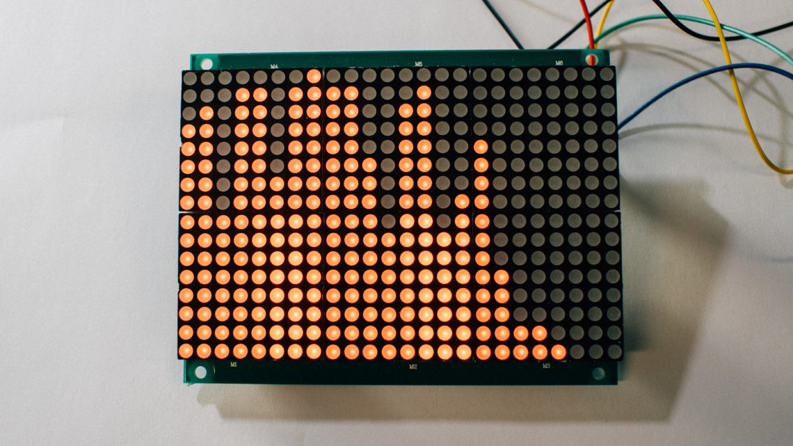
In our latest blog post we wrote about the enclosure on this “LED Matrix with Rolling Particles”.
But how is it to use? And what happens on the inside?
Continue to read this post to find out!
What Does It Do?
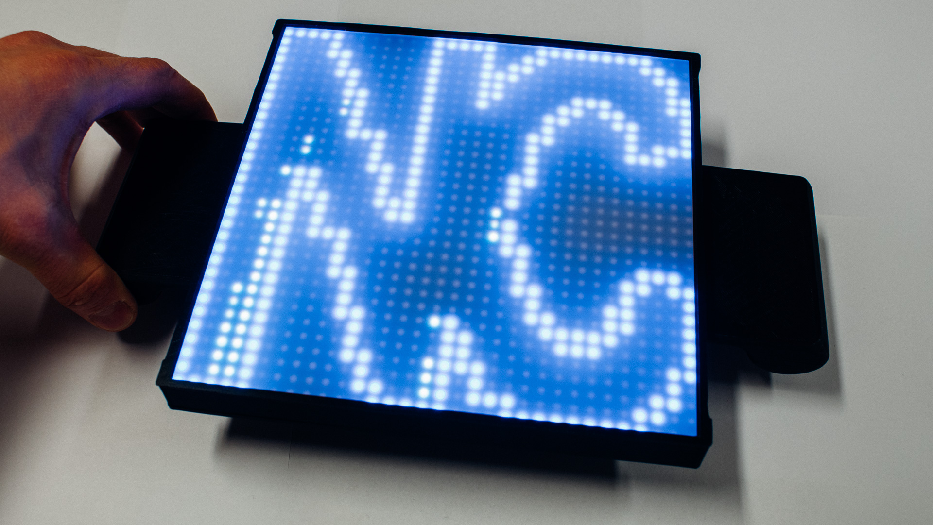
We wanted to gamify this a bit, so we made a small opening in the C letter giving the simulated particles a way out.
A typical game would be to get as many particles out as possible within a given time.
The Inside
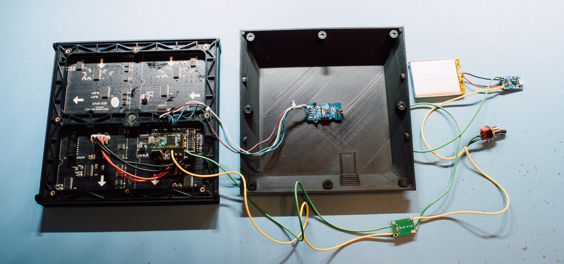
This was put together by using different things we had lying around.
If we were to make one from scratch we would probably not have used the different components used here!
We used, among other things:
- A SmarMatrix Shield for the interface between the LED matrix and the Teensy 3.1
- A Teensy 3.1
- A32*32 LED Matrix
- A Grove IMU – For the accelerometer readings
The Firmware
The firmware that runs on this is a combination of different sources. Most of the “heavy lifting” is done in external libraries, but the “glue logic” had to be implemented.
And many things here were used because of the hardware in the system!
Libraries used because of the hardware in the system:
- SmartMatrix3 3.1.0
- FastLED 3.2.1
- Grove IMU 9DOF 1.0.0
And the particle simulation was done with the PixelDust library.
Initialization
We included the following:
#include <SmartMatrix3.h> // For LED matrix
#include <Wire.h> // For accel
#include <I2Cdev.h> // For accel
#include <MPU6050.h> // For accel
#include "Adafruit_PixelDust.h" // For simulation
#include "NC_logo.h"  // the NC logo
#include "NC_logo_mask.h"  // the NC logo-mask
The Led Matrix and the “visuals” was given the following:
#define COLOR_DEPTH 24                  // known working: 24, 48 - If the sketch uses type `rgb24` directly, COLOR_DEPTH must be 24

const uint8_t kMatrixWidth = 32;        // known working: 16, 32, 48, 64
const uint8_t kMatrixHeight = 32;       // known working: 32, 64, 96, 128
const uint8_t kRefreshDepth = 36;       // known working: 24, 36, 48
const uint8_t kDmaBufferRows = 4;       // known working: 2-4, use 2 to save memory, more to keep from dropping frames and automatically lowering refresh rate
const uint8_t kPanelType = SMARTMATRIX_HUB75_32ROW_MOD16SCAN;   // use SMARTMATRIX_HUB75_16ROW_MOD8SCAN for common 16x32 panels
const uint8_t kMatrixOptions = (SMARTMATRIX_OPTIONS_NONE);      // see http://docs.pixelmatix.com/SmartMatrix for options
const uint8_t kBackgroundLayerOptions = (SM_BACKGROUND_OPTIONS_NONE);

SMARTMATRIX_ALLOCATE_BUFFERS(matrix, kMatrixWidth, kMatrixHeight, kRefreshDepth, kDmaBufferRows, kPanelType, kMatrixOptions);
SMARTMATRIX_ALLOCATE_BACKGROUND_LAYER(backgroundLayer, kMatrixWidth, kMatrixHeight, COLOR_DEPTH, kBackgroundLayerOptions);

rgb24 sand_color = {0x90, 0x90, 0x90}; // dimmed white
rgb24 logo_color = {0x00, 0x00, 0xff}; // blue
The “sand” was define as such:
#define WIDTH kMatrixWidth
#define HEIGHT kMatrixHeight

#define N_GRAINS 30 // Number of grains of sand
#define MAX_FPS 40 // Maximum redraw rate, frames/second

// sand = new Adafruit_PixelDust(w, h, n, s, e, sort);
// w: Simulation width in pixels (up to 127 on AVR, 32767 on other architectures).
// h: Simulation height in pixels (same).
// n: Number of sand grains (up to 255 on AVR, 65535 elsewhere).
// s: Accelerometer scaling (1-255). The accelerometer X, Y and Z values passed to the iterate()
// function will be multiplied by this value and then divided by 256, e.g. pass 1 to divide
// accelerometer input by 256, 128 to divide by 2.
// e: Particle elasticity (0-255) (optional, default is 128). This determines the sand grains'
// "bounce" -- higher numbers yield bouncier particles.
// sort: If true, particles are sorted bottom-to-top when iterating. Sorting sometimes (not always)
// makes the physics less "Looney Tunes," as lower particles get out of the way of upper particles.
// It can be computationally expensive if there's lots of grains, and isn't good if you're
// coloring grains by index (because they're constantly reordering).

Adafruit_PixelDust sand(WIDTH, HEIGHT, N_GRAINS, 10, 128, false);
Some more things done before setup:
// Default I2C address: 0x68
MPU6050 accelgyro;

int16_t raw_ax, raw_ay, raw_az;
int16_t raw_gx, raw_gy, raw_gz;
int16_t raw_mx, raw_my, raw_mz;

// Used for frames-per-second throttle
uint32_t prevTime = 0;

// draw a pixel with "logo_color" where the image is 0 (inverted)!
void draw_logo(int16_t x, int16_t y, uint8_t * bitmap) {
  for(unsigned int i=0; i < LOGO_WIDTH; i++) {
    for(unsigned int j=0; j < LOGO_HEIGHT; j++) {
      if(bitmap[j*32+i] == 0) backgroundLayer.drawPixel(i,j,logo_color);
    }
  }
}
And the “setup” was executed like this
void setup()
{
  // debug serial
//  Serial.begin(115200);

  // I2C
  Wire.begin();

  // Run I2C at 400 KHz
  Wire.setClock(400000);

  accelgyro.initialize();

  // 0 = +/- 2g
  // 1 = +/- 4g
  // 2 = +/- 8g
  // 3 = +/- 16g
  accelgyro.setFullScaleAccelRange(1);

  matrix.addLayer(&backgroundLayer);
  matrix.begin();

  // set the overall matrix brightness (0-255)
  matrix.setBrightness(255);

  sand.begin();

  // draw the obstruction pixels. Remember that the mask is inverted
  for(uint8_t x = 0; x < LOGO_HEIGHT; x++){
      for(uint8_t y = 0; y < LOGO_WIDTH; y++){
        if(!NC_logo_mask[y*32+x]) sand.setPixel(x,y);
    }
  }


  // set starting position for all grains. Use the mask
  uint8_t n = 0;

  for(uint8_t x = 0; x < LOGO_HEIGHT; x++){
    for(uint8_t y = 0; y < LOGO_WIDTH; y++){ // okey to place a grain there? if(NC_logo_mask[y*32+x]){ sand.setPosition(n++,x,y); } // break the loop if all grains are placed if(n >= N_GRAINS){
        x = LOGO_HEIGHT;
        y = LOGO_WIDTH;
      }
    }
  }
  delay(100);
}
“The Loop”
The “main loop” looks as following:
void loop()
{

  // Limit the animation frame rate to MAX_FPS.  Because the subsequent sand
  // calculations are non-deterministic (don't always take the same amount
  // of time, depending on their current states), this helps ensure that
  // things like gravity appear constant in the simulation.
  uint32_t t;

  // TODO: Overflow secure micros()!
  while(((t = micros()) - prevTime) < (1000000L / MAX_FPS));
  prevTime = t;

  // Display frame rendered on prior pass.  It's done immediately after the
  // FPS sync (rather than after rendering) for consistent animation timing.

  // clear screen
  backgroundLayer.fillScreen({0,0,0});

  // draw the logo
  draw_logo(0,0,NC_logo);

  // Draw new grain positions
  dimension_t x, y;
  for(uint8_t i=0; i<N_GRAINS; i++) {
    sand.getPosition(i, &x, &y);
    backgroundLayer.drawPixel(x, y, sand_color);
  }

  // display the filled buffer
  backgroundLayer.swapBuffers();

  // Read accelerometer
  accelgyro.getMotion9(&raw_ax, &raw_ay, &raw_az, &raw_gx, &raw_gy, &raw_gz, &raw_mx, &raw_my, &raw_mz);

  sand.iterate(raw_ay, raw_ax, raw_az);
}
Wrap-up
This was a fun little device to make, both in terms of electronics, firmware and enclosure. Yes, it can (and probably will) be optimized a bit, both in terms of firmware and mechanics, but we’re pretty happy with how it turned out now. This wraps up this short blog series. Until next time, keep making!