About three months ago we wrote a post about a vehicle platform we’re building.
Since then we’ve mostly waited for parts, primarily the aluminium plates. Now that the parts have arrived, we’ve started building the vehicle chassis.
Current State
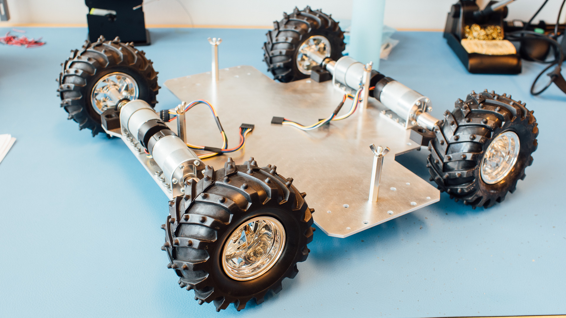
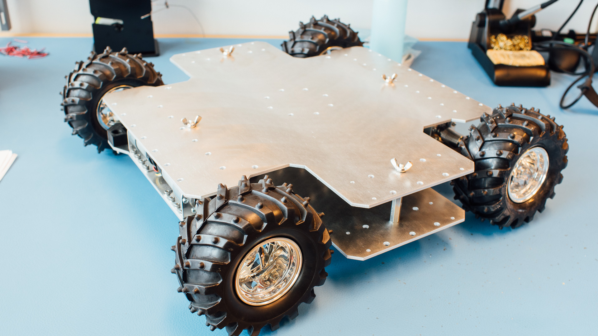
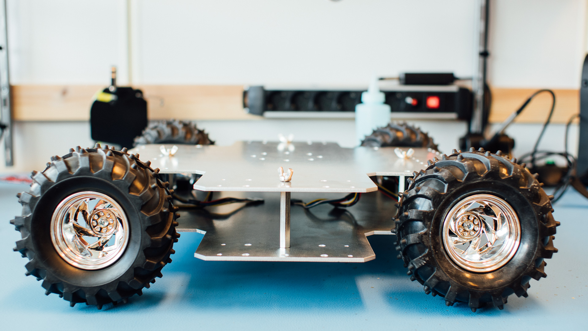
The laser cut aluminium plates (cut by this bad boy) ended up being 3 mm thick. This is a good compromise between rigidity and weight in our case. Since last post we’ve redesigned the plates a bit with more mounting holes and a different spacer setup, rotated into a diamond shape instead of a rectangle shape. The reason for the new spacer setup was due to wider plates which we wanted to support on the sides to prevent them from flapping around.
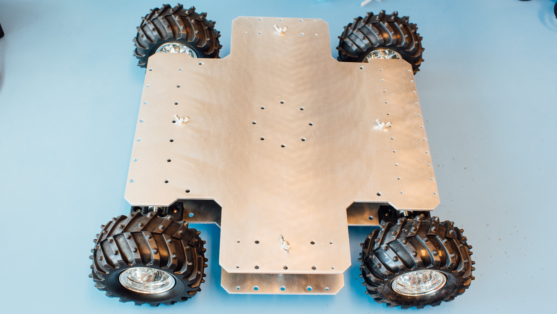
The spacers themselves work great. The whole structure is very robust and the wing nuts makes it easy to “pop the hood”.
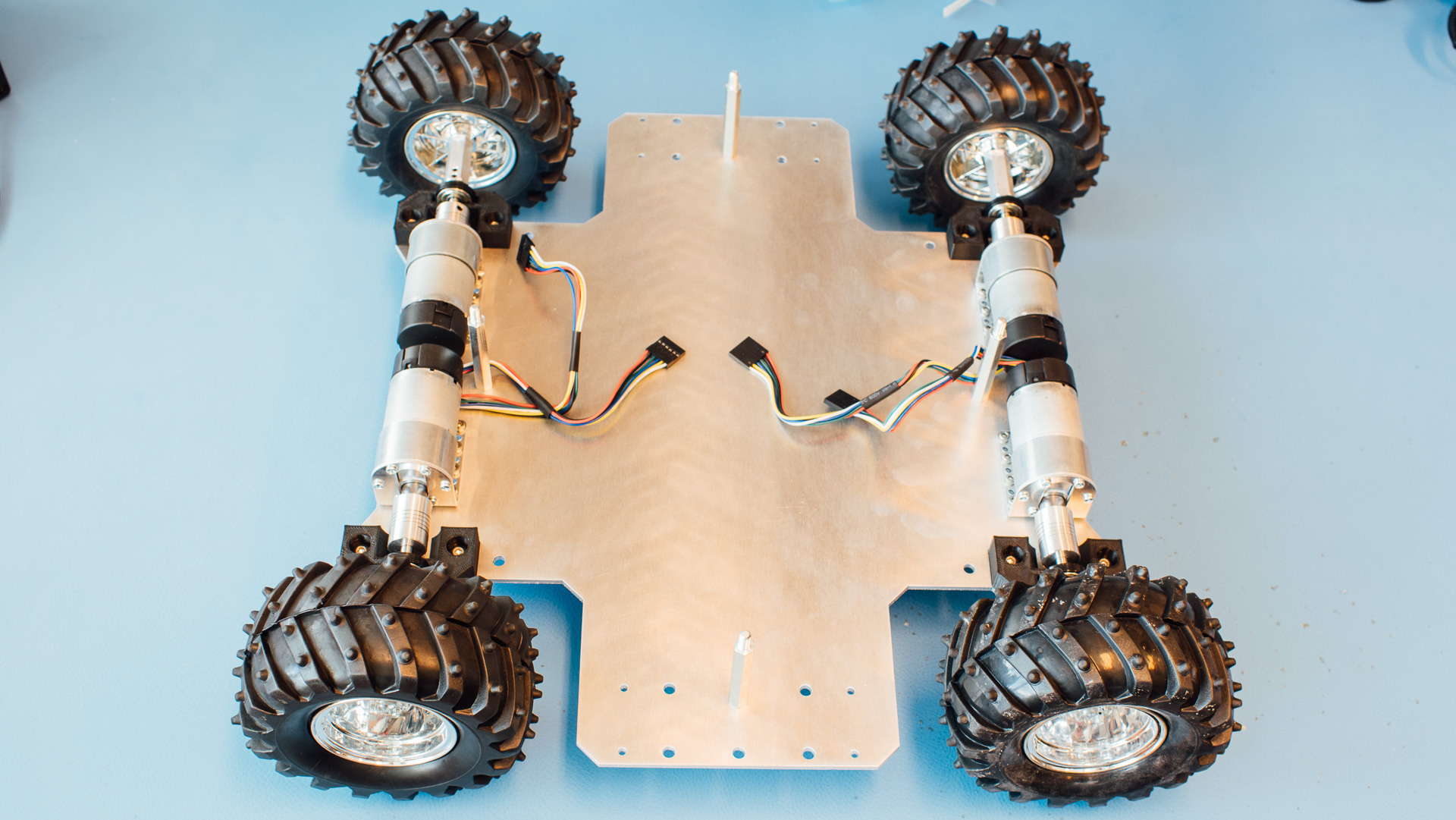
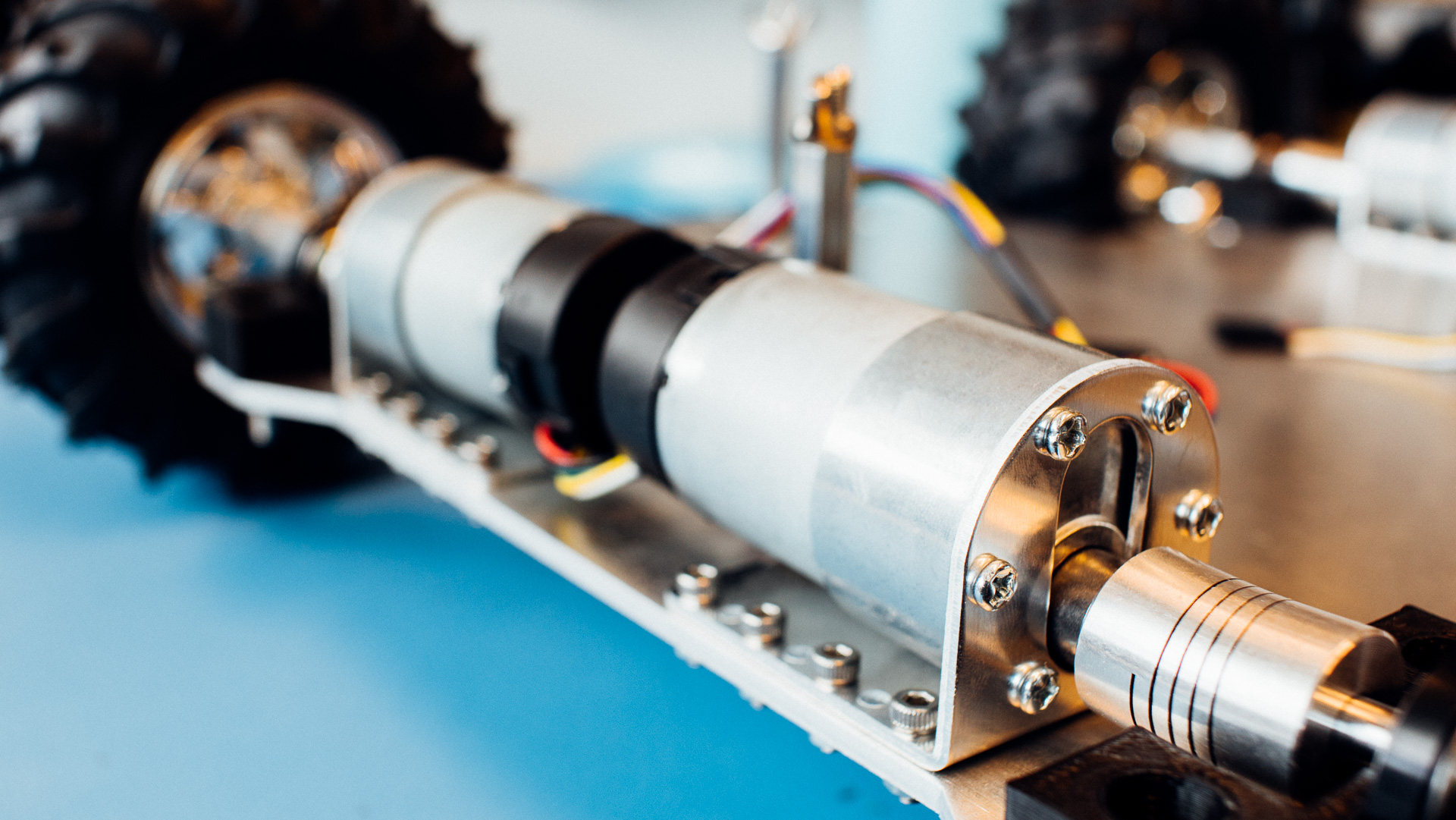
The brackets for the motors are not completely 90 degrees, thus the shaft angle out from the motor is not horizontal. Luckily we have flexible couplers which solve this issue.
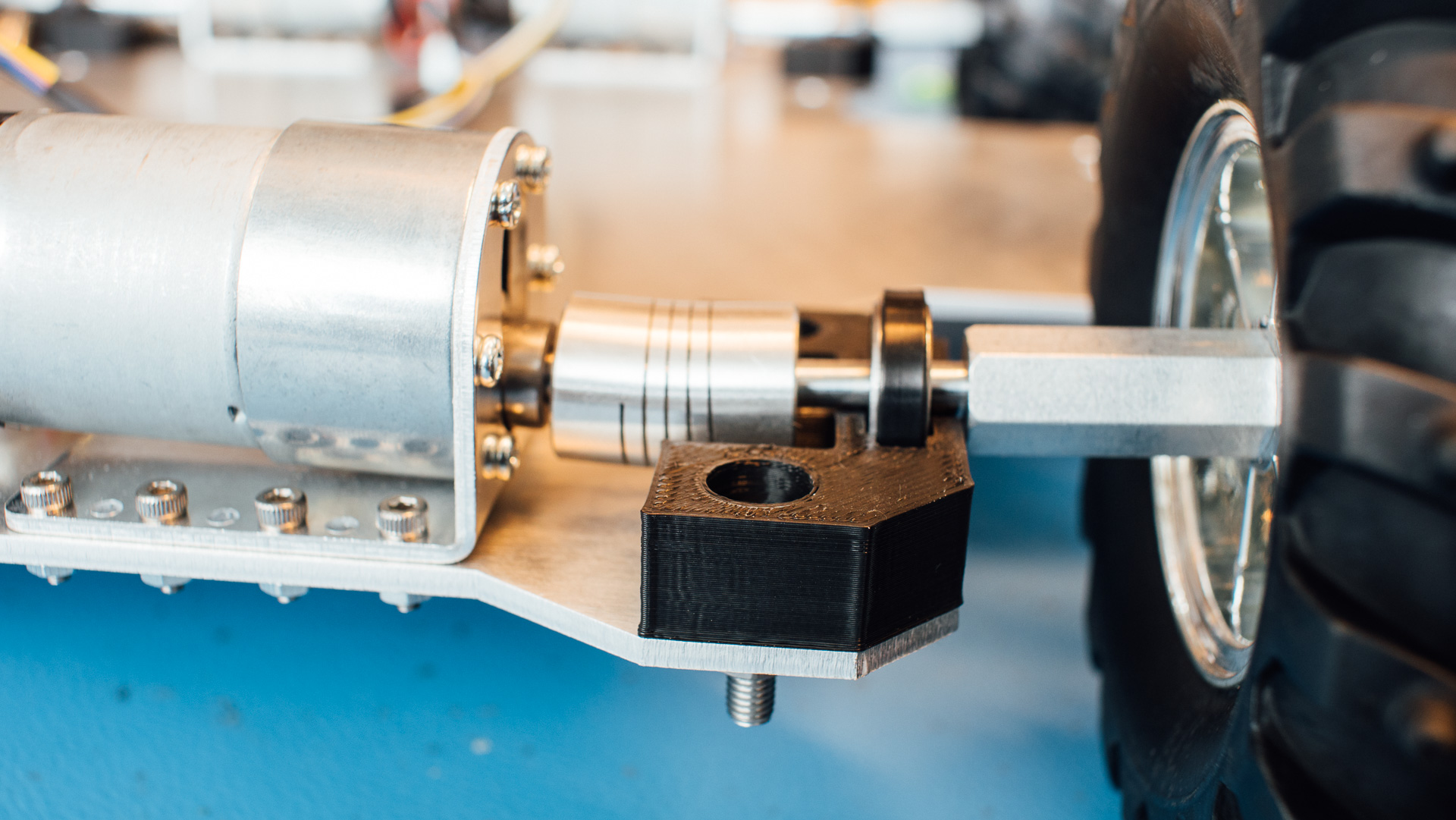
The bearings are fastened with zip-ties, which is a sub-elegant solution. The next revision might have a proper house made up of two 3D printed parts with the bearing sandwiched between them.
Speaking of next revisions and bearings: double bearings with some space between them is something we’ll consider at a later stage since this will stabilize the wheel shafts a bit more and relieve the motor shaft and coupler more than with the single bearing. The current setup, however, is sufficiently robust for now.
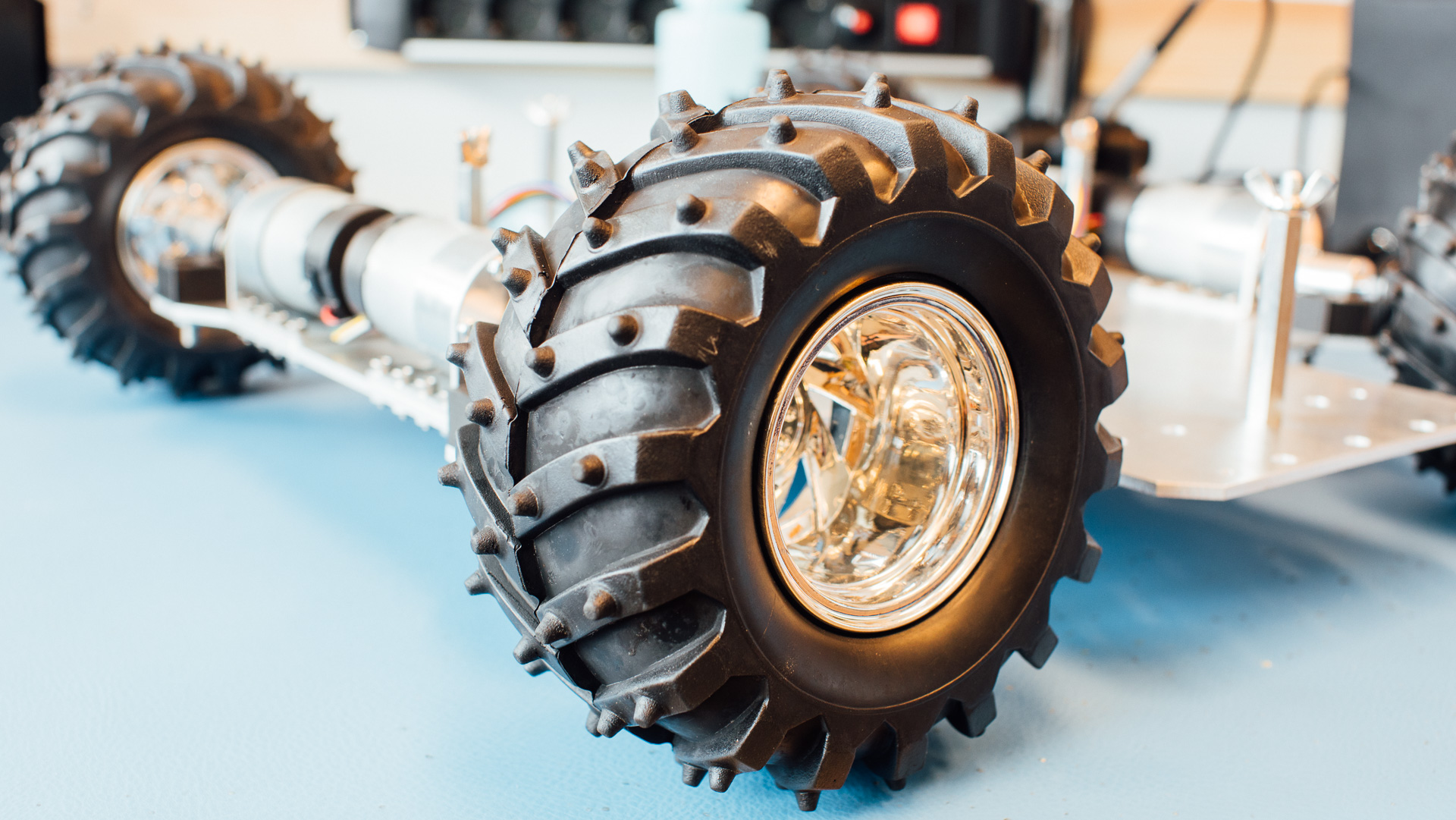
We originally wanted red rims, but we feel that the chrome ones are sufficiently cool.
The Way Forward
Next up is to design and produce a motherboard which will handle the power management and tie the Teensy, receiver, the two motor drivers and the battery together. Expect several additional blog posts about this project in the not too distant future. Until next time: happy making!