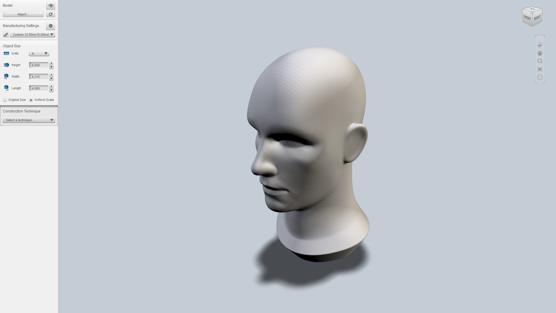
The short answer is Autodesk 123D Make.
You might think we’re getting paid by Autodesk to write all these posts about their software. This is not the case, but as a maker you should really be aware of some of their free software solutions since they might make your life a bit easier.
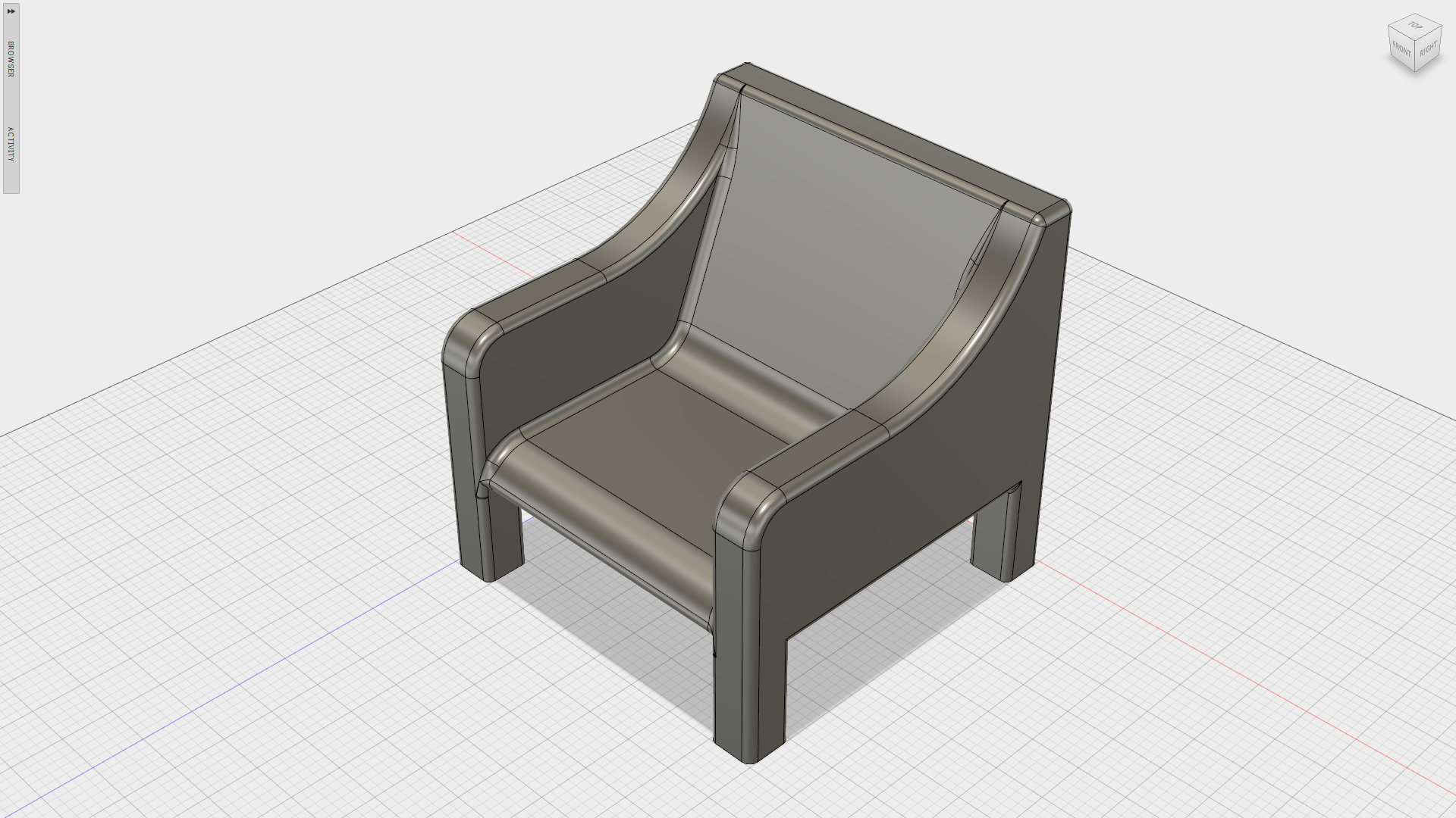
So, back on topic. Say you have a CNC mill and some 15mm plywood sheets which you want to create a cool looking chair out of. Not initially a trivial task, but with 123D Make things suddenly get pretty trivial, and best of all: it’s completely free.
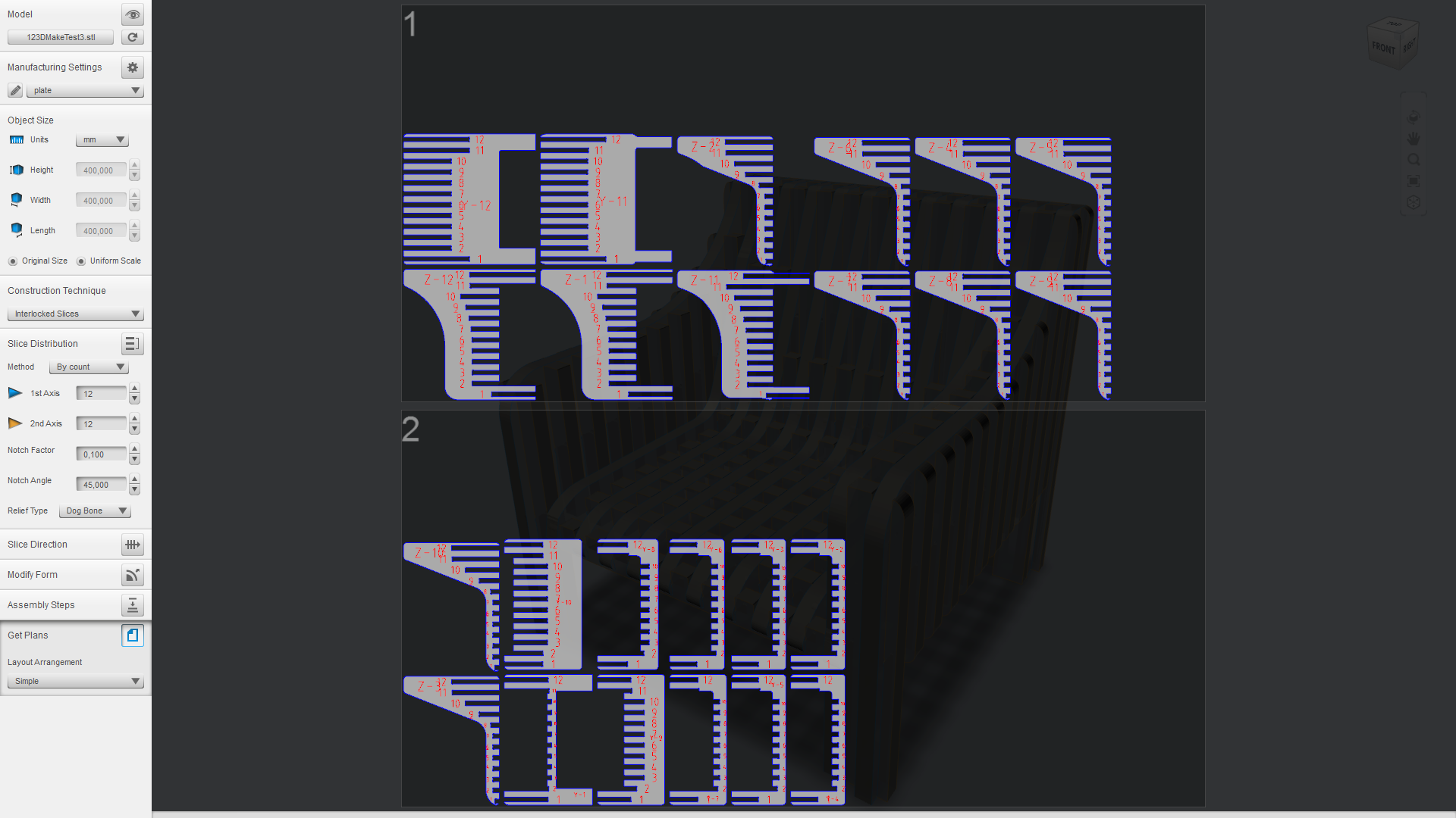
Model the chair in a CAD program; import your .stl file; choose the dimensions of your material, tooling and slot offset (tolerance); choose and customize the desired technique; export 2D-layout (.eps, .pdf or .dxf) for CAM where all the pieces are automatically optimally positioned on the sheet. Easy, useful and fun!
An Overview of 123D Make’s Techniques
This software has several techniques which it uses to realize the model. We’re going to go through one by one.
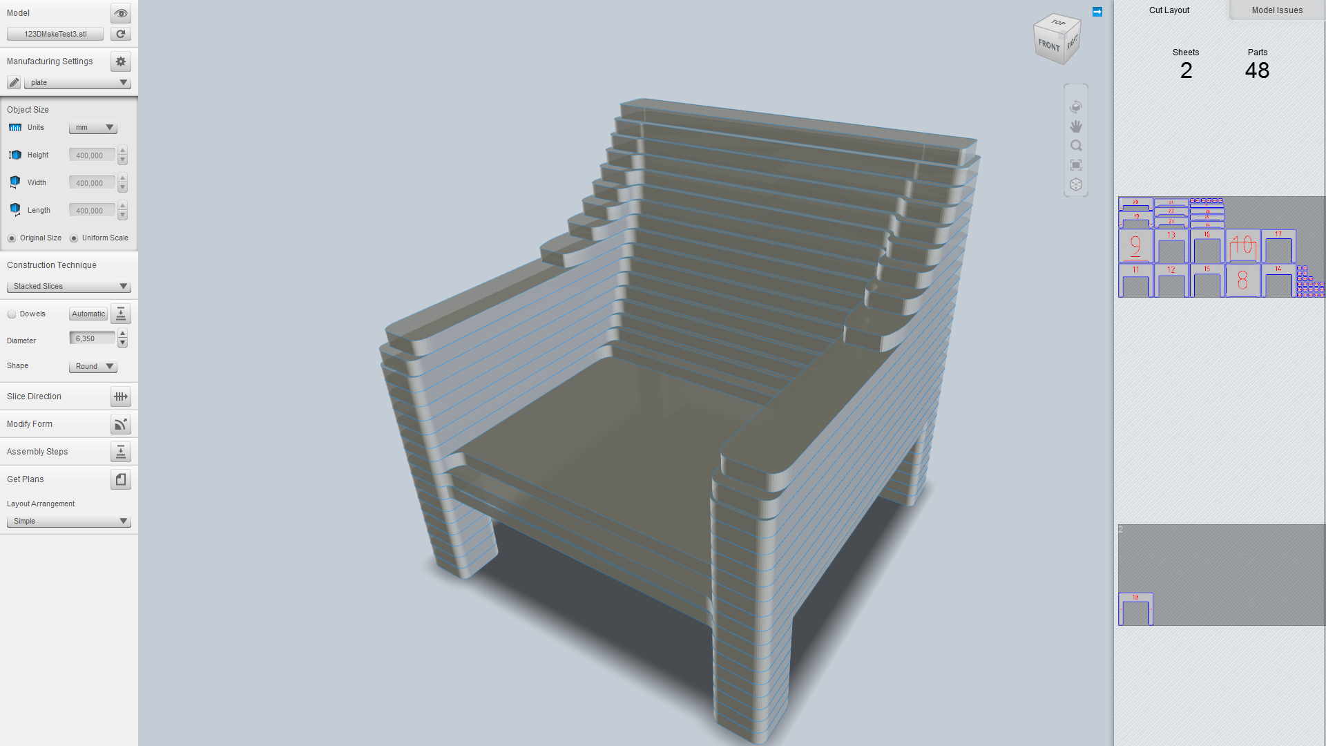
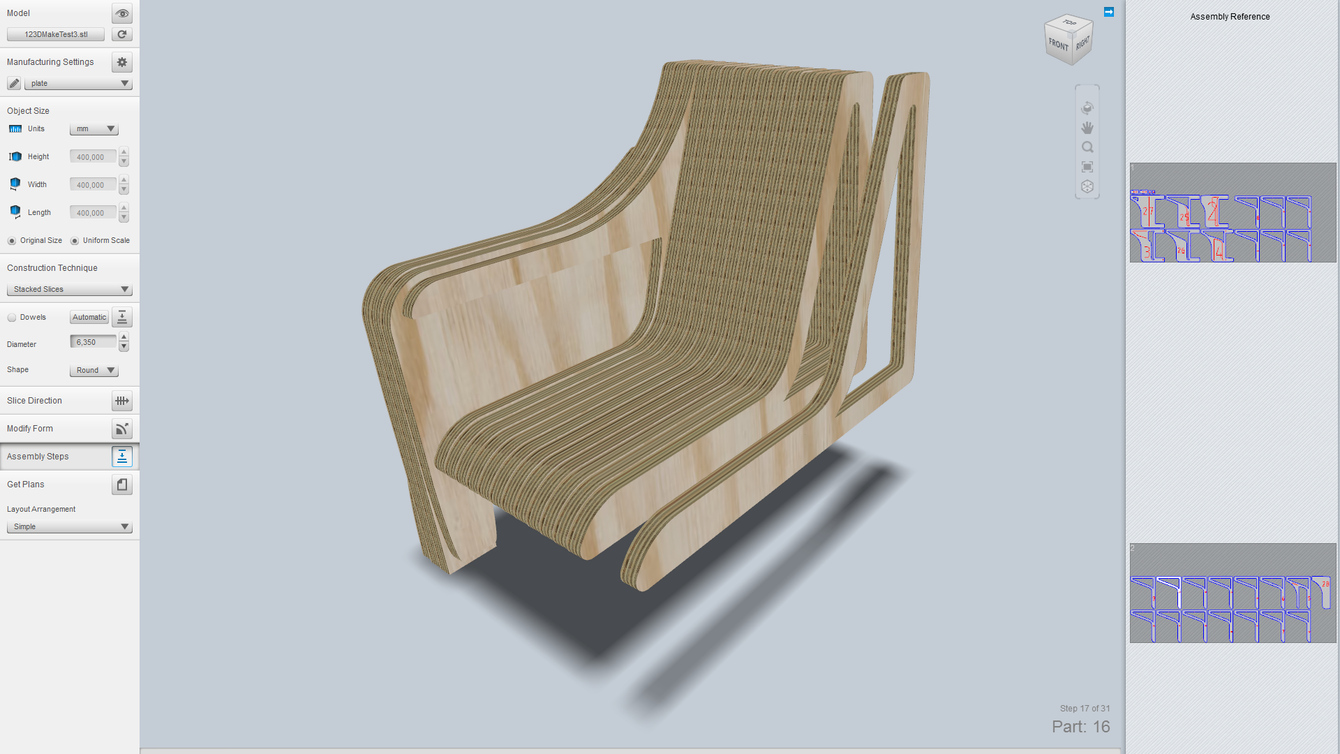
Stacked Slices
The most basic technique 123D Make has to offer. This technique stacks slices right on top of eachother in whatever angle you desire. One downside is that this technique requires a large amount of material for sizable models.
One nice feature is the optional, but automatically positioned dowels which makes it easier to align the slices on top of eachother. You can also hollow the structure to make it less massive.
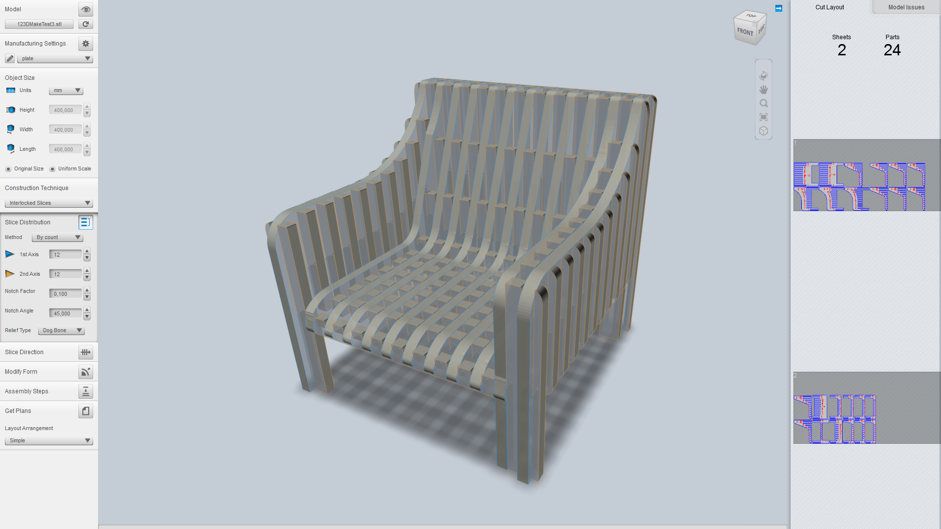
Interlocked Slices
This technique is probably what you can call 123D Make’s “signature technique”.
Suitable for larger models such as furniture, interlocked slices makes slots in each piece so that they slide into eachother, kind of like some sort of puzzle. You can choose how many slices each of the two axes should contain or how much space there should be between each slice. You can also customize the slice direction as well as several other parameters.
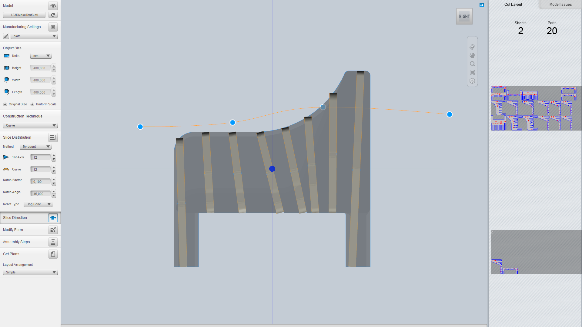
Curve
Pretty similar to interlocked slices, except that one of the axes can be curved by manipulating a bézier-like curve. By a curved axis we mean that the slices along that axis won’t be parallel to eachother.
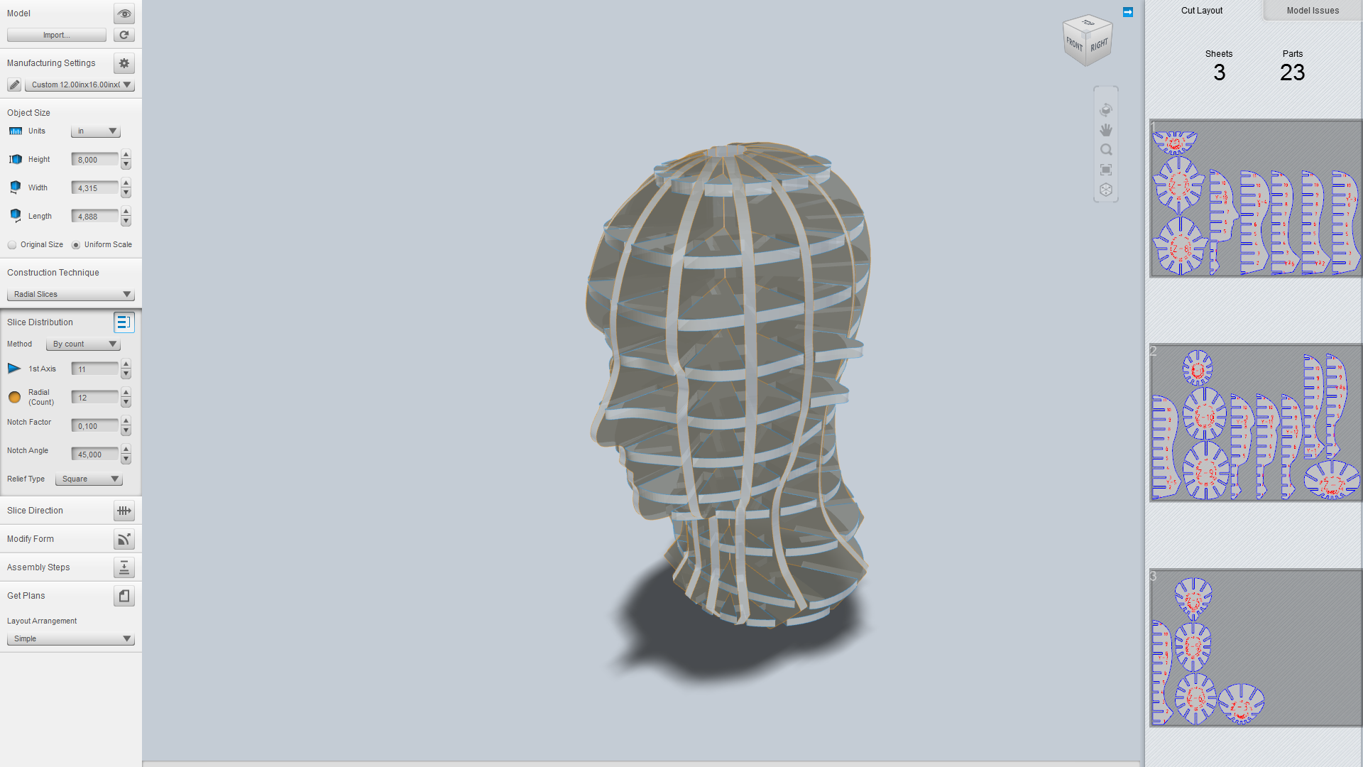
Radial Slices
Much of the same concept like the previous two techniques except that the whole slice layout is radial instead of grid-based. Looking at the image below, you’ll see exactly what we’re trying to explain. 🙂
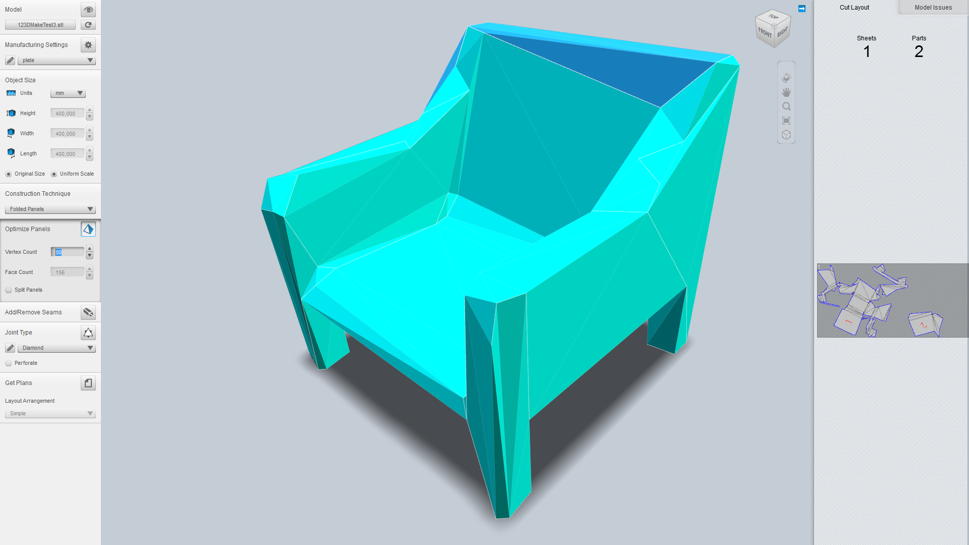
Folded Panels
Imagine you have a sheet of thick paper you want to fold to make it form the surface of an object. Or imagine a reversed organge peeling operation. This is basically that. You can decrease or increase the vertex count to make the result simpler or closer to the original, respectively. You can also split all the panels so that all the sides are isolated from eachother. There are several interesting joint types you can select from as well as a perforation option.
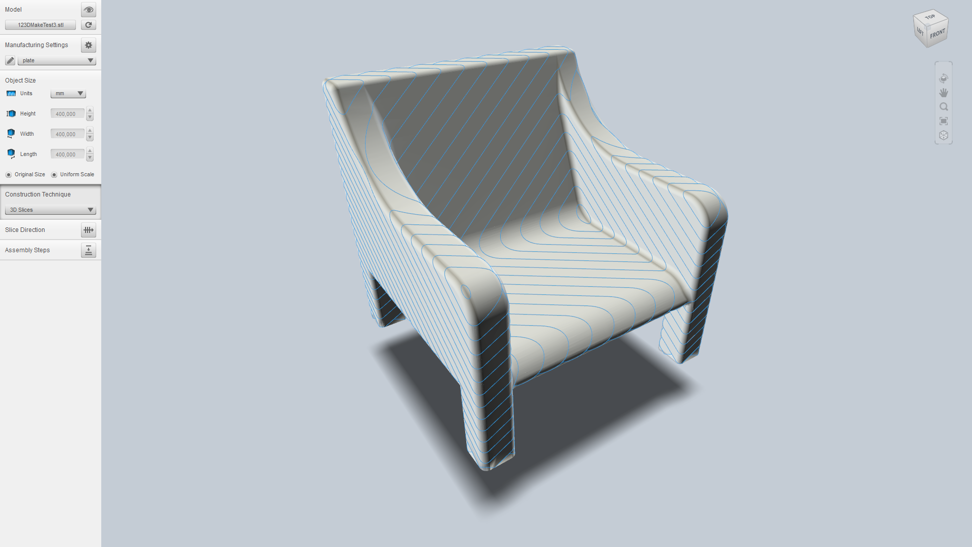
3D Slices
Pretty similar to stacked slices, except that the edges are sloped to exactly match the model, making the result 100% similar to the original model. The usefulness of this technique is a bit cryptic to us at this time since there’s no way to export the individual slices as we know of. With a ball nose end mill tool it would be possible to realize this technique using a CNC mill – if you could export 3D-models of each slice (you would then have to 3D-CAM it).
Other Features
123D Make will in real-time check that the layout is possible to manufacture and assemble. If for instance a piece is too large or it will be practically impossible to assemble the interlocked slices, it will show what and where the error is. If you encounter layout errors, try changing the slice direction.
Another neat feature is the assembly steps viewer where you can see an animated visualization of how to assemble the slices (not available in folded panels). This is typically useful in complex layouts with many interlocked slices.
Concluding Words
123D Make is a neat piece of software which you can use to get the most out of your sheet CNC mill or laser cutter. Interlocked slices and its related techniques is a really handy feature which lets you create larger three-dimensional constructions without having to worry too much about how it should be fastened together.
And best of all: it’s completely free.