It took me 1 hour to design the model, and it takes 1 hour to machine it using a CNC. Why does it take 5 hours total?? 1 + 1 equals 2, NOT 5!?
In this post we will explain the basic workflow when going from the drawing board to a finished machined part.
The workflow can be divided into 3 parts: Designing -> CAM -> Machining
Designing is where you design your creation, CAM is the often overlooked part where the appropriate machine is programmed to make your designed part, and the last step, Machining, is where the actual part is made. We explain these 3 steps more in detail in the next 3 paragraphs.
Designing
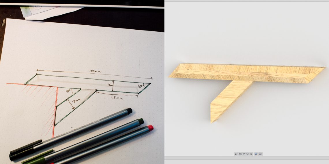
This section is where you design your part. It’s common to start out in the analog domain, with everything from some napkin sketches, to cardboard models.
After you have an overview of how the part should look you should “digitize” the drawings. This is necessary because you have decided that the best method to make the part is by using a CNC machine, and when doing that you need a digital model of the part.
Digital drawing tools have both been difficult to use and it has been difficult to really understand how the finished part will look and work. But the last couple of years the different tools have all introduced a lot of great features, such as animations and fast rendering, making it easy to get an impression of how the part would look in real life.
So it’s possible to jump straight into the digital drawing domain, abandoning the whole analog model making fun.
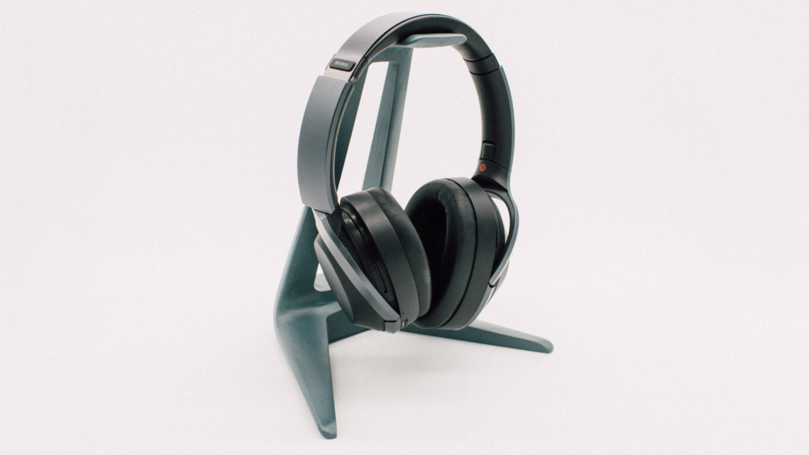
The fact that you understand how the digital model will look in real life, is no guarantee for that other people understand it. Therefore, making a physical model is often necessary to make other people understand. This is the main reason model building is so common among architects. 3D-printing can be of great help here!
When you have the digital model ready, you’re ready to go on to the next step. Namely, programming the CNC machine to make your part.
CAM
Many people think it’s a direct link between the digital model and the actual machining. But it’s not. This step is where all the overlooked hours go.
CAM is an abbreviation of “Computer-aided manufacturing”. This is the step where you program the appropriate CNC machine to do your specific job. You make the “toolpath”/program the specific machine to be able to make your design.
This includes selecting things such as the correct tools, feed rates and speeds. Many of these factors are affected by the material the part is going to be made out of.
And how does the part look? Is it possible to do everything from one side? Or is it necessary to turn the part around, attaching it again, aligning everything, and continue machining from another angle?
Is the material easy to machine? Such as wood or plastic? Those materials are pretty forgiving when it comes to feeds and speeds, meaning it will not ruin your day if you don’t machine with perfect parameters. But materials such as different metal alloys put greater demands on your programming skills. In cases like this we recommend using tools such as this wizard to calculate different maching parameters.
The selected material also sets requirements for the end mills (tools) you need to use. This post over at Make: explains this aspect.
When you have tooling and material, you need to figure out how fast the machine is going to do the job, and how fast the spindle is going to turn the tool around. Theoretical parameters can be calculated and that gives you a good starting point. But remember that your machine also set some limitations on these numbers. Therefore, use a log book and track key parameters for each machining job!
The Shapeoko CNC machine is a great little machine, and this page is a community created collection of key figures from machining different materials.
When you have a decided upon things such as what kind of end mills, feedrates, speeds and how much material the machine should remove each pass (“Depth of Cut” and “Width of Cut”), it’s time to create the toolpaths.
Toolpaths in plural because it’s often necessary to do the specific job in many steps. This can be because of the need to use different tools (one for making many small holes and another to cut the outline).
This toolpath generation is what divides the Wheat from the Chaff. Finding the optimal combination of parameters such as tools, feeds and speeds is not trivial, and trial and error is often needed!
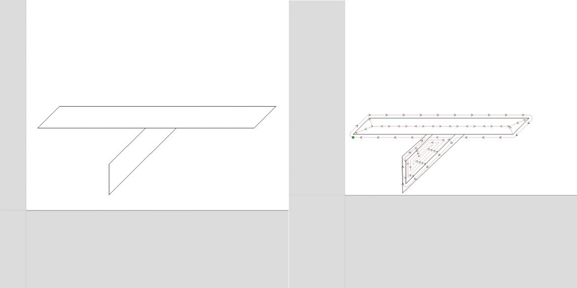
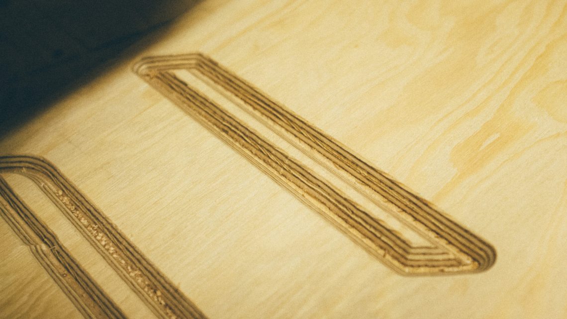
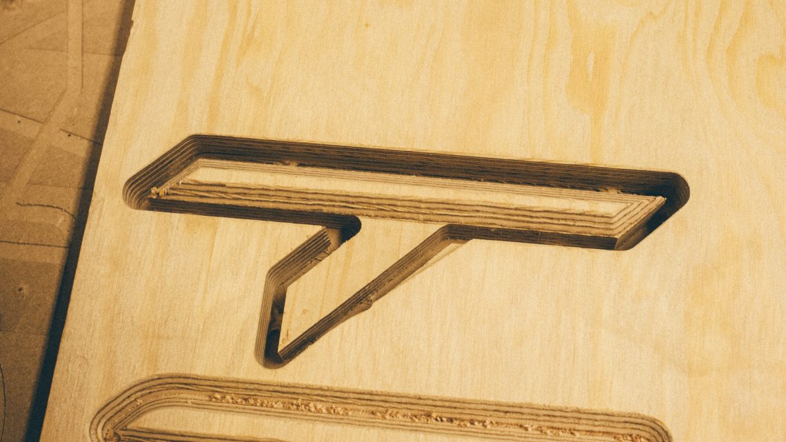
We divided our part into 3 different toolpaths:
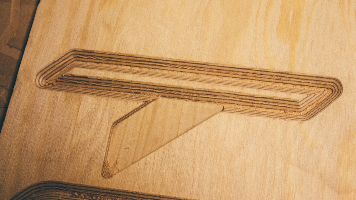
- The chamfer around the top bar
- The pocket down on the arm
- The final profile (including tabs)
When you have the toolpaths nailed down we can continue over to the machining part.
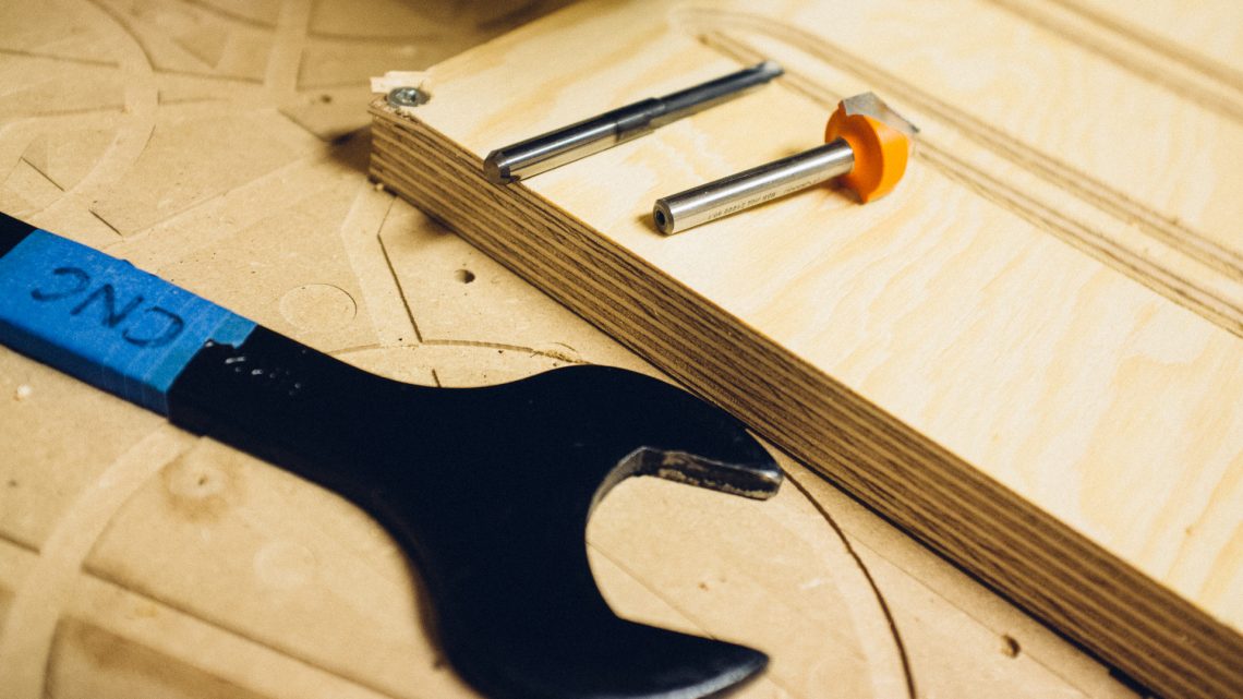
Using what we had at the moment we decided upon these parameters (using this specific machine):
- Tools: 90 degree 2 flute V-angled bit and a 1 flute straight. Both from with 6 mm shank.
- Spindle speed: 10k RPM (V-carve tool) and 24k RPM (straight tool)
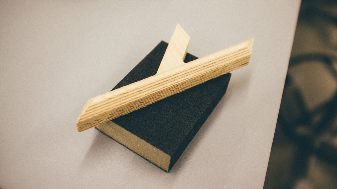
- Material: 18 mm birch plywood
- Feed rate: 1000 mm/min
- Depth of Cut (step down): 3 mm
Machining
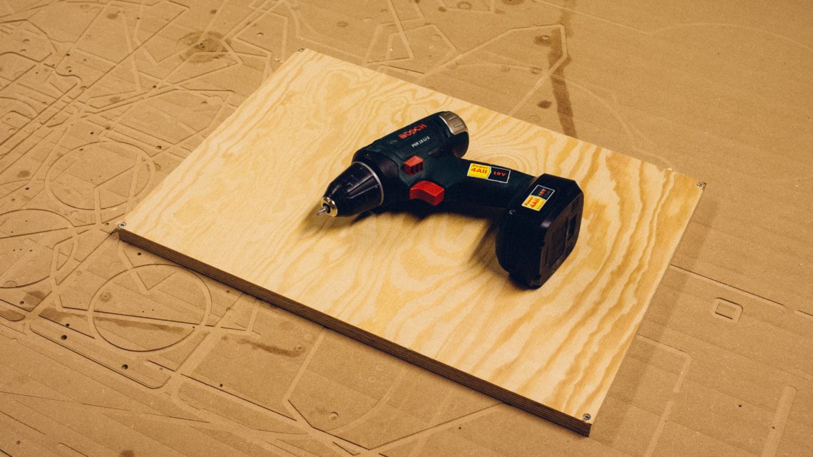
First you need to attach the material to the machine. It’s of grave importance that the part is firmly fixed. You don’t want it to come flying or vibrate later on, making the job a real mess.
How the piece should be attached depends on the machine. If it has a vacuum board, a waste board or a rail system.
All of those hold down methods work great for different kinds of jobs. A vacuum board is the most expensive and maybe most hassle to install, a rail system can work great, but it often has to be customized for a specific material size. A waste board is cheap and often a great start.
This specific machine use a waste board. So first we attached the material to this board using standard wood screws.
When machining the outline of your part, the part will loosen from your material. And that can be a real bummer. So therefore, you need to figure out how to hold down everything until machining is complete.
Tabs is a common thing to add, but it makes it necessary to manually remove the machined part from the material afterwards.
If you need a clean cut edge around the outside you need to attach the complete part. This can be done halfway out in the job (in a pause), using some of the machined features such as holes, or you can attach the whole part to the waste board using things such as double sided tape or glue.
This particular job needed to be done using two different tools. And this machine does not have an automatic tool changer.
DOWNLOAD

This work is licensed under a Creative Commons Attribution-ShareAlike 4.0 International License.
You can download the 3D-model here.
Final words
You don’t need a machining-degree to machine “soft” materials such as wood and plastics. A couple of hours “googling” and “youtubing” combined with a handful trial and error will get you there in a jiffy.
CNC-ing is like any kind of “Maker-activitiy”: something that is best learned through experience. So get your machine running and master this skill!