As you probably read in this post, capacitance is a measure of the ability to store energy. They are among other things used in rectifiers, as bypass devices and in analog filter circuits.
They are super-important components and critical for making sure applications and other components work.
But how do you measure this super-important “size” (the “capacitance”)
The Time Constant and the Circuit
The time constant is defined as the time it takes for a system to reach a given state from a step input.
In this case we want to find “C” and a circuit with only a capacitor and a resistor (in series) have a known time response.

And that shall we exploit!

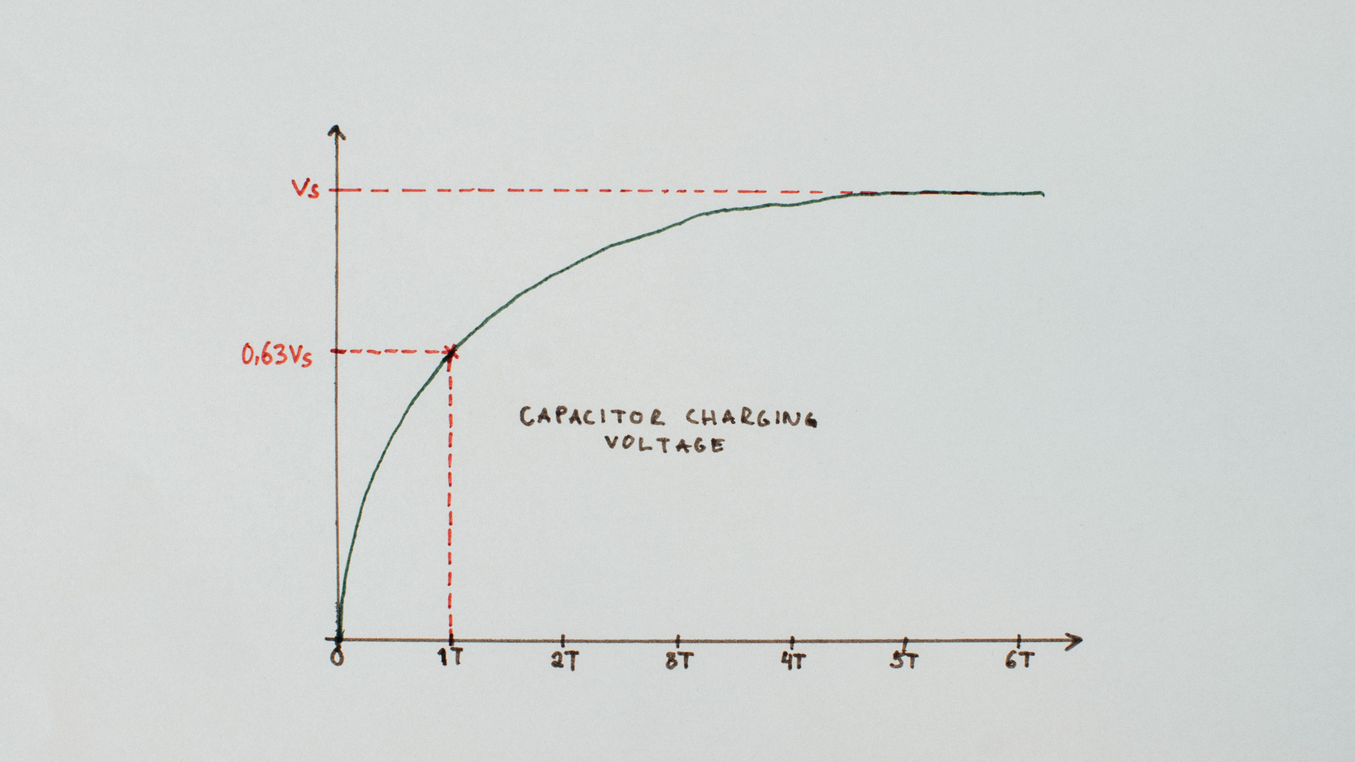
So to measure the capacitance of the Capacitor we can just charge it up through a known resistor and measure the time it takes before it reaches ~63,2% of the charging voltage!
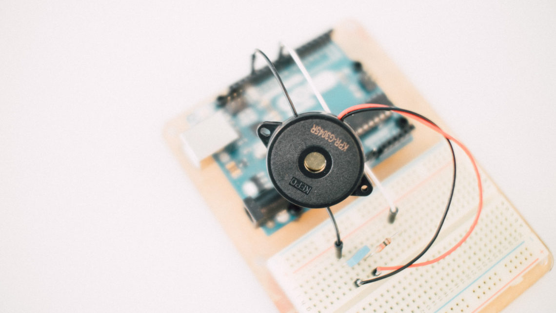
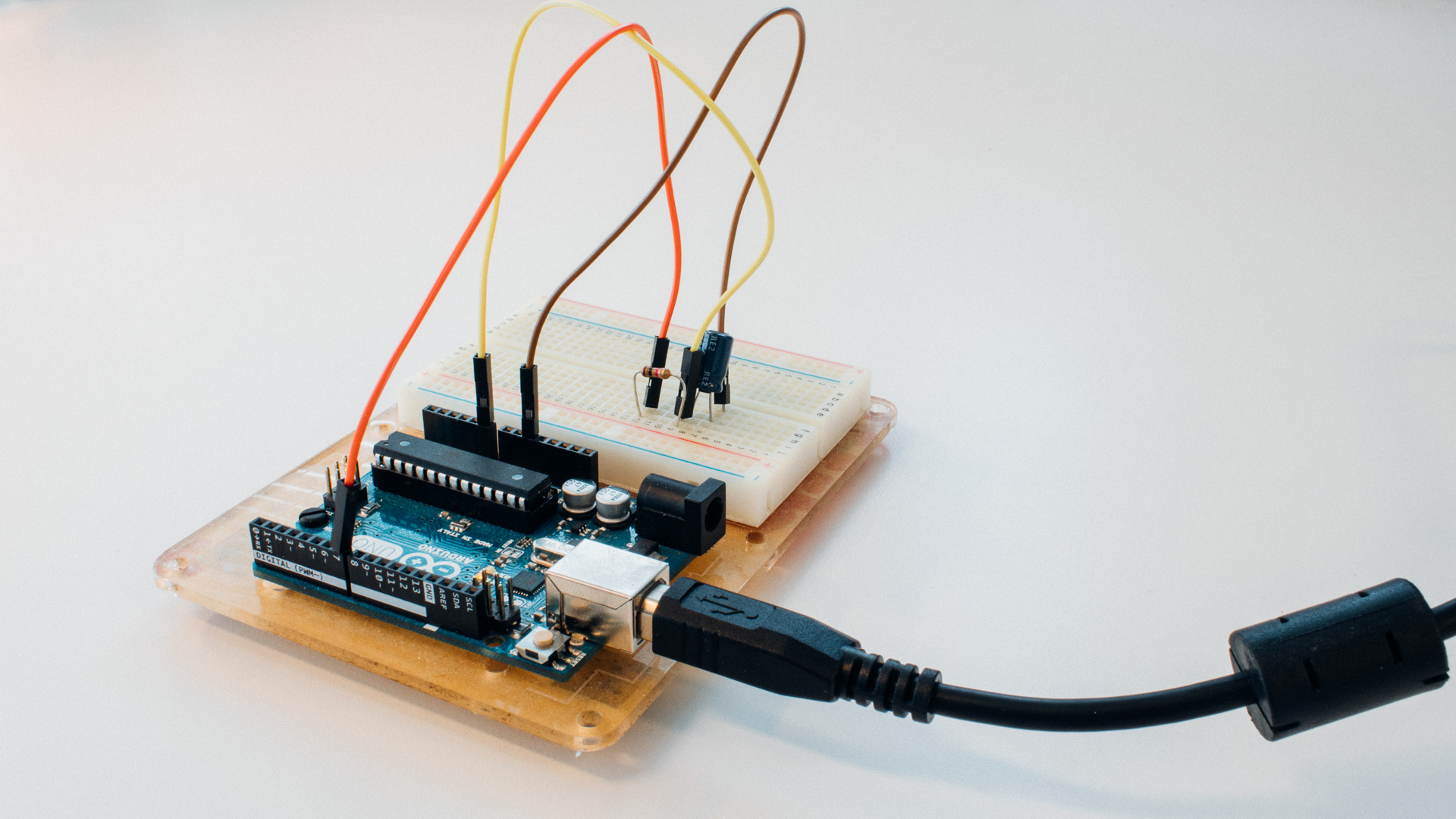
The circuit is rather simple:
- The capacitor under test is connected in series with a known resistor (here: 10 k Ohm).
- The capacitor circuit is connected to pin 7 on the Arduino.
- The capacitor was also connected to an analog input on the Arduino to measure the voltage (A0).
The Firmware
The firmware to do this measurement does 3 measurements, averages the result, and prints out the final answer printed on the serial (USB).
The flow is as following:
- The Arduino discharges the capacitor circuit by setting pin 7 low. It makes sure the capacitor is empty by reading the voltage over it.
- It starts charging the capacitor circuit and starts the timer.
- It continues charging until the capacitor until it reaches 3,16 volt (~63,2% of 5 V).
- When the circuit reaches 3,16 volt it saves the accumulated time value and goes back to 1 if this is done less than 3 times.
- The final answer are an average of all the measurements and the result are printed out on the serial port!
#define NO_MEASSUREMENTS 3

#define analog_pin     A0
#define capacitor_pin  7

#define resistor_value   989000.0F // the value on the resistor in Ohms

unsigned long start_time = 0;
unsigned long accumulated_time = 0;

void setup() {
pinMode(capacitor_pin, OUTPUT);

Serial.begin(115200);
}

void loop() {

accumulated_time = 0;

for(uint8_t i = 0; i < NO_MEASSUREMENTS; i++){

// Make sure the capacitor is dicharged
digitalWrite(capacitor_pin, LOW);
while(analogRead(analog_pin) > 0){}

// set chargePin HIGH and capacitor charging an
digitalWrite(capacitor_pin, HIGH);
start_time = micros();

// 647 is 63.2% of 1023, which corresponds to full-scale voltage
while(analogRead(analog_pin) <= 647){}
accumulated_time += (micros() - start_time);
}

float result_time = ((float) accumulated_time) / NO_MEASSUREMENTS;

float micro_F = ( result_time / resistor_value) * 1000;

Serial.print((long)result_time);
Serial.print(" us before tau / ");

print_float(micro_F, 2);
Serial.println(" uF");
}

// from Peter H. Anderson, Baltimore, MD
void print_float(float f, int num_digits)
{
int pows_of_ten[4] = {1, 10, 100, 1000};
int multiplier, whole, fract, d, n;

multiplier = pows_of_ten[num_digits];

if (f < 0.0){
f = -f;
Serial.print("-");
}

whole = (int) f;
fract = (int) (multiplier * (f - (float)whole));

Serial.print(whole);
Serial.print(",");

// print each digit with no leading zero suppression
for (n=num_digits-1; n>=0; n--){
d = fract / pows_of_ten[n];
Serial.print(d);
fract = fract % pows_of_ten[n];
}
}
This came out from the Serial Monitor:
105404 us before tau / 106,57 uF
(The Capacitor under test was stated 100 uF “big”. This difference can be caused by many different things. Among others: Inaccurate timing, ADC (un)accuracy, power supply imprecision and of course: Difference between stated and actual capacitance from the manufacturer).
Conclusion
As we saw here: You can measure capacitance using a simple mathematical “bond” that exists between time, resistance and capacitance and a simple and cheap circuit.
But note that this need some “upgrades” (especially on the hardware-side) to become a “high precision” measurement device.