In this post we’ll show you a simple example on how to use a rotary encoder to move a stepper motor in real time, aka. jogging. This will be done using a standard stepper motor driver, but without any shields and/or libraries.
There are several motion controller libraries one can use where all of this is implemented and abstracted to the user (Grbl, Smoothieware, etc.).
Other stepper motor related tutorials on our blog:
- Arduino Tutorial: Stepper Motor with Easy Driver
- Tutorial: Calibrating Stepper Motor Machines with Belts and Pulleys
You can check out a newer blog post as well: Arduino as a Stepper Motor Controller – Jogging with acceleration
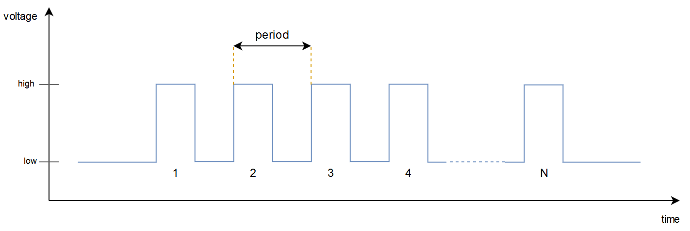
Our aim will be to move a stepper motor a certain amount of steps each time the Arduino receives a pulse from the encoder. The Arduino will produce a so called pulse train and send it to the motor driver.
Pulse Train Parameters
There are two important parameters of this pulse train:
- Number of pulses (N in the visualization above)
- The number of pulses to produce and send to the driver each time we get a pulse from the encoder.
- The larger this number is, the longer the motor runs when the Arduino gets a single encoder pulse.
- Period
- The time elapsed between each pulse.
- The smaller this number is, the faster the motor moves. Too fast will result in loosing steps.
- Without a proper acceleration profile, we need to be careful and not set this parameter too low.
Pins
In our case we need to configure 5 pins on the Arduino.
Rotary Encoder Pins
- Pulse – the encoder will send pulses when being manipulated.
- Direction – this pin will indicated whether you rotate the encoder clockwise or anti-clockwise.
Stepper Motor Driver Pins
- Step – this is where we send the pulse train.
- Direction – decides which way the motor will rotate.
- Enable – this need to be set to “turn on” the motor driver.
Code Example
The code will have a buffer which stores all steps that will be sent to the driver. The motor will continue moving in one direction until the buffer is empty. Only then are you able to change direction. Notice that we use an interrupt to read the rotary encoder.
#define ENCODER_PULSE_PIN 2
#define ENCODER_DIR_PIN   3
#define DRIVER_STEP_PIN   8
#define DRIVER_DIR_PIN    9
#define DRIVER_EN_PIN     10

#define STEPS_PR_ENCODER_PULSE  10
#define DRIVER_PULSE_PERIOD_US  1600

enum Driver_pulse_state_enum {PULSE_IDLE, PULSE_HIGH, PULSE_LOW};

uint8_t dir = LOW;
uint16_t pulse_buffer = 0;
unsigned long time_now = 0;
uint16_t driver_pulse_hold_time_us = DRIVER_PULSE_PERIOD_US/2;
uint8_t driver_pulse_state = PULSE_IDLE;

void setup() {
  pinMode(ENCODER_PULSE_PIN, INPUT);
  pinMode(ENCODER_DIR_PIN, INPUT);
  pinMode(DRIVER_STEP_PIN, OUTPUT);
  pinMode(DRIVER_DIR_PIN, OUTPUT);
  pinMode(DRIVER_EN_PIN, OUTPUT);

  attachInterrupt(digitalPinToInterrupt(ENCODER_PULSE_PIN), encoderISR, RISING);

  digitalWrite(DRIVER_EN_PIN, HIGH);
}

void loop() {
  if((pulse_buffer) && (driver_pulse_state == PULSE_IDLE)){
    driver_pulse_state = PULSE_HIGH;
    digitalWrite(DRIVER_DIR_PIN, digitalRead(ENCODER_DIR_PIN));
    digitalWrite(DRIVER_STEP_PIN, HIGH);
    time_now = micros();
  }

  if((micros() - time_now > driver_pulse_hold_time_us) && (driver_pulse_state == PULSE_LOW)){
    driver_pulse_state = PULSE_HIGH;
    digitalWrite(DRIVER_STEP_PIN, HIGH);
    time_now = micros();
  }

  if((micros() - time_now > driver_pulse_hold_time_us) && (driver_pulse_state == PULSE_HIGH)){
    digitalWrite(DRIVER_STEP_PIN, LOW);
    time_now = micros();

    pulse_buffer -= 1;
    if(pulse_buffer < 0){
      pulse_buffer = 0;
    }

    if(pulse_buffer){
      driver_pulse_state = PULSE_LOW;
    }
    else{
      driver_pulse_state = PULSE_IDLE;
    }
  }
}

void encoderISR(){
  pulse_buffer += STEPS_PR_ENCODER_PULSE;
}
The STEPS_PR_ENCODER_PULSE parameter is the number of pulses we send to the driver each time we get a reading from the rotary encoder. DRIVER_PULSE_PERIOD_US decides the time period between each pulse in microseconds for the pulse train.
Improving the Functionality
One way to make this code cooler can be to empty the buffer and start to move the opposite direction if the Arduino receives an encoder pulse with a direction opposite to how the motor is currently running. As it is now, the system needs to empty the buffer before the motor can run in the opposite direction.
We can also implement different control modes, for instance use a potentiometer to adjust the speed and a toggle switch to select direction.
A more important functionality is to have a proper acceleration profile. This way we can achieve faster speed without losing steps, and the movement will become much smoother. We will look at how you can create something like this in a later blog post.
Continue reading about Arduino as a Stepper Motor Controller – Jogging with acceleration here.