Previous posts in this series:
If you’re unsure about how capacitors and/or inductors work, check out:
In this post we’re going to examine what happens in circuits with resistors and inductors (RL circuits), resistors and capacitors (RC circuits), but not all three (RLC circuits). More specifically, we’re going to look at what happens in these types of circuits when we either open or close a switch inside the circuit. This is called the natural response and the step response, respectively.
If you want to learn more about the mathematics and this subject in general, we recommend the book Electric Circuits by Nilsson & Riedel.
RL Circuits
Let’s examine some properties of RL circuits.
The Natural Response of RL Circuits
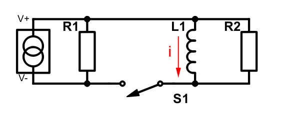
Let’s take a look at the following circuit and assume that the switch has been in closed state long enough for the current through the circuit to stabilize.
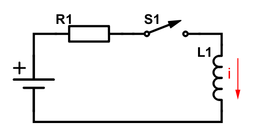
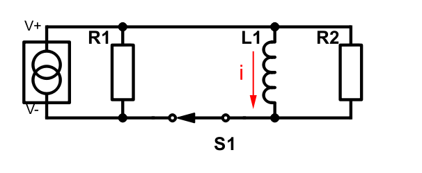 The symbol to the far left is a constant current source. This is a theoretical example, so all of the current will go clockwise through the inductor since we don’t have any resistance there. When we open the the switch the circuit will look like this:
 The inductor’s ability to store energy will make it continue to supply current through the R2 resistor in a counter-clockwise direction. We’ll just focus on this right-side loop for now. To avoid confusion we’ll keep the subscripts from the above schematics in the equations to come.
Remember that the voltage across an inductor is L di/dt? Let’s use this together with Kirchoff’s voltage law:
![]()
From this equation we can go through a few steps of mathematical acrobatics and get the following expression:
![]()
where I0 is the current at the moment the switch is opened (t = 0). Also: t ≥ 0.
As you might know, or have guessed, t is time in seconds. So, the current that goes round and round in the loop will decrease as time goes by. This can be seen in the graph below:
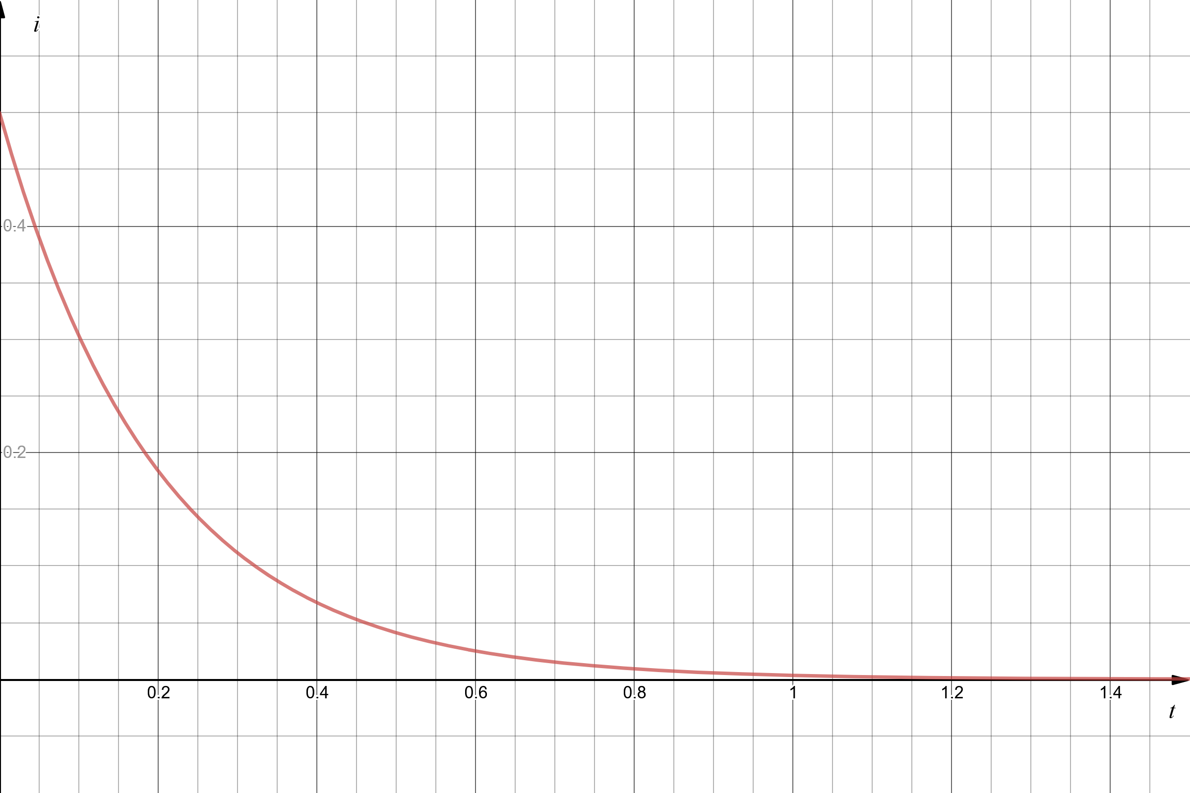
In this example I0 is 500 mA, R2 is 10 Ω and L1 is 2 H.
As long as we have the expression for the current, finding the voltage across the resistor is super easy. We just apply Ohm’s law directly:

The Step Response of an RL Circuit
So what happens with the current when we go from this
 to this?
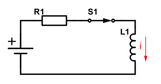 Notice that the power source is a voltage source instead of a current source. Let’s call the voltage it supplies to the circuit for Vs.
Again, let’s apply Kirchoff’s voltage law around the loop:
![]()
We need to conduct some mathematical acrobatics again to arrive at the final expression:
![]()
In our particular case I0 is 0 A (the circuit is open). This is how the current changes over time when we close the switch at t = 0:
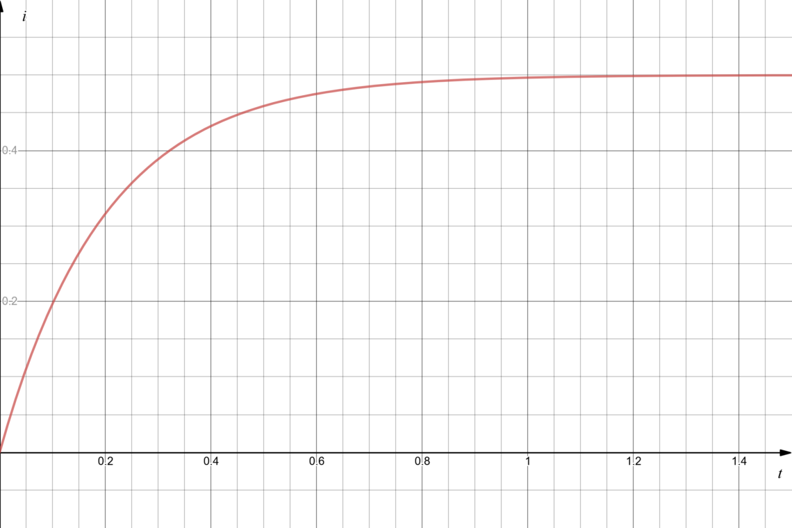
In this example Vs = 5 V, R2 = 10 Ω and L1 = 2 H.
So, what about the voltage across the inductor? We know that this is L di/dt. Thus we need to differentiate the last equation with regards to t and multiply with L1. We then get the following expression for voltage across the inductor as a function of time:
![]()
for t ≥ 0.
Let’s plot this for clarity with the same parameters as before:
RC Circuits
Let’s examine the equivalent topics with capacitors instead of incuctors!
The Natural Response of an RC Circuit
In the natural response example we’ll use the following circuit:
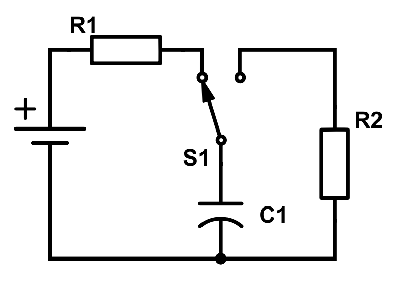
Imagine that the switch has been in this state for a long enough time such that everything is stabilized. Then, at t = 0, we toggle the switch and end up with this circuit:
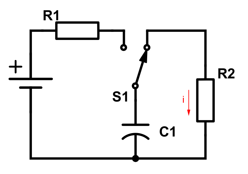
Similarly to the RL example, we will concentrate on the right loop. After being charged before t = 0, the capacitor will work as a voltage source in the circuit with R2.
The capacitor’s initial voltage at t = 0 is equal to the voltage supply’s voltage. Let’s call this V0.
To get an expression for the voltage across the capacitor we need to do a trick. Let’s use the bottom junction as a reference node and add the currents out from the upper node between S1 and R2. This gives us the equation:
From this we can do the usual mathematic acrobatics and end up with:
![]()
which is the voltage across the capacitor over time. As with all these other functions, this is only valid for t ≥ 0.
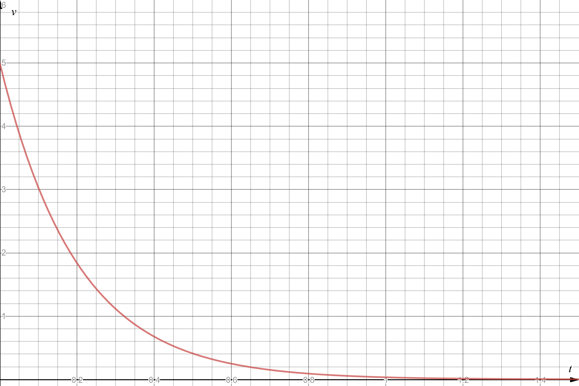
Let’s see what this looks like in practice with a 5 V voltage source, a 100 mF capacitor and a 10 Ω R2 resistor:
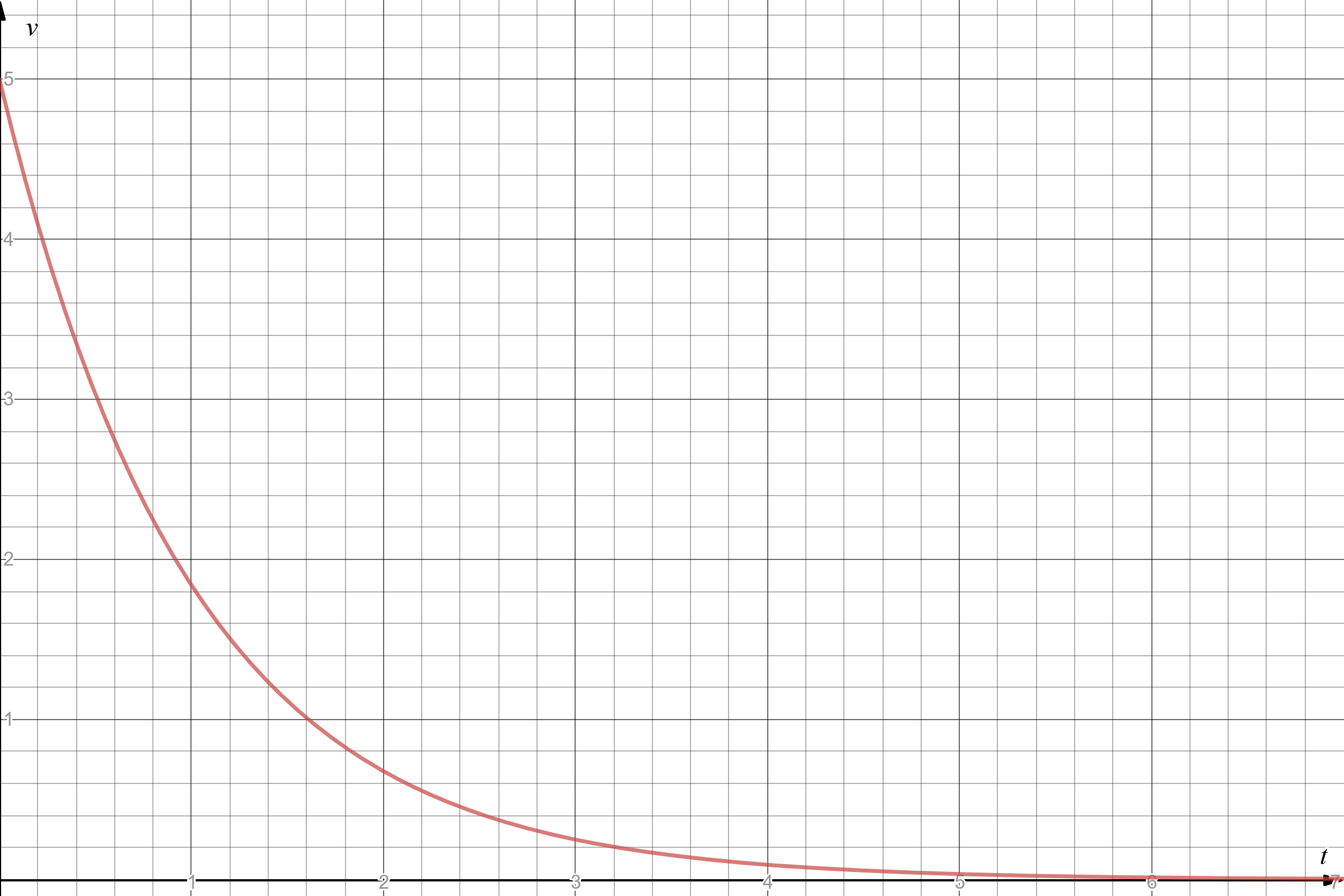
Pretty similar as the other ones, right?
The current flowing through the capacitor and R2 after t = 0 can easily be found by applying Ohm’s law directly:
![]() for t ≥ 0.
for t ≥ 0.
The Step Resonse of an RC Circuit
This is this post’s last round of circuits, equations and graphs where we’ll look at RC circuits’ step response. Let’s start with this circuit:
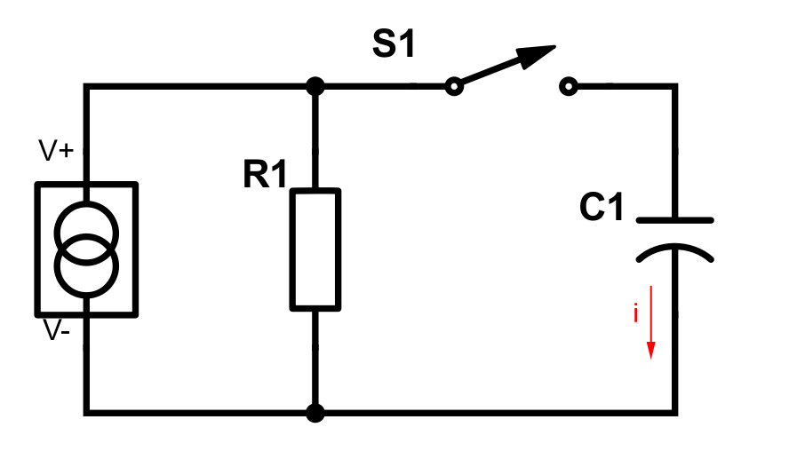 Note the constant current source. We’re going to call the supply current Is. As per usual we close the switch at t = 0, but we won’t draw that particular circuit in this case (you probably get the idea by now).
Applying Kirchoff’s current law to the top node, we get:
From this, by mathematical magic, we get a function of the voltage across the the capacitor:
![]()
for t ≥ 0.
V0 is the initial voltage across the capacitor at t = 0. This is in our case 0 V.
Let’s graph!
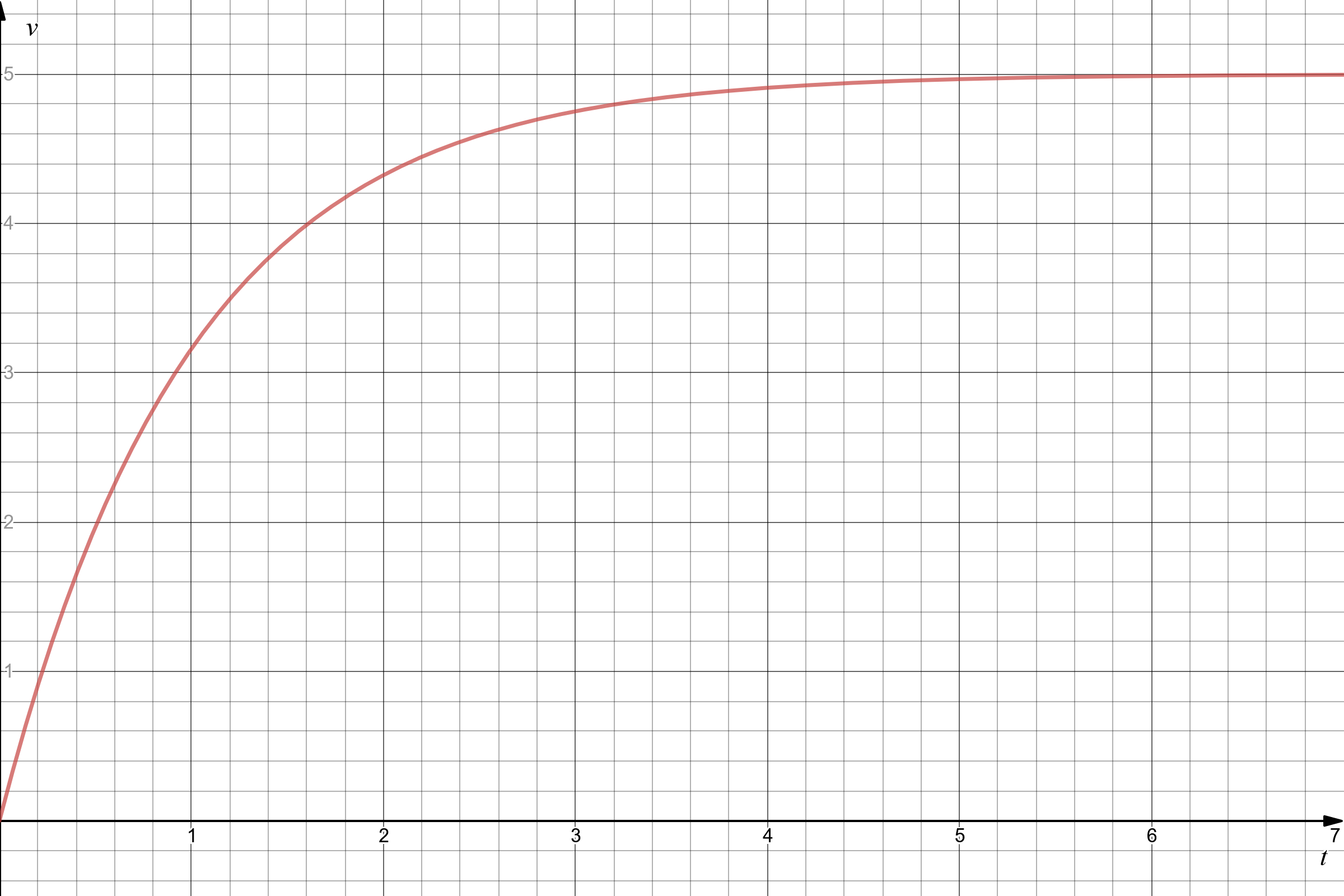
The usual parameters: Is = 500 mA, R1 = 10 Ω, C1 = 100 mF.
The current flowing through the capacitor is:
![]()
for t ≥ 0.
By now you’ll probably guess how the graph will look, so we won’t bother making one.
The Time Constant
In the equations in this post we’ve several times written R/L and RC. The time constants for RL and RC circuits are
- L/R (inverse of how it’s written in our equations) and
- RC
respectively.
This time constant is usually denoted by τ and defines how long it takes from t = 0 to a steady state. For instance, in our first example with the current in the natural response of an RL circuit, if t = τ then the current is reduced to e-1 (approx. 37%) of the initial value.
So, if you stumble across the τ symbol or the time constant term in topics like this, you’ll now know what it means.
Summary
As you can probably tell, capacitors and inductors are closely related. In a way you can say they are the inverse to one another. The only thing that decides the time aspect of the behavior in the scenarios mentioned in this post is the combination of the resistor value and the capacitor or inductor size (aka. the time constant).
Next time we’ll look at RLC circuits, which combines both resistors, inductors and capacitors.