Using Arduino to simplify programming is nothing new. There are Arduino libraries for almost everything, and with one or more of these in hand you can make awesome gadgets, even as a clueless beginner. Programming LEDs is no exception, and the FastLED library certainly simplifies this process.
In this post we’re going to talk a bit about digital LEDs in general as well as give some examples on how to use the FastLED library.
What Are Digital RGB LEDs?
One answer to this is LEDs that you can individually control with a low amount of wires (independent of the number of LEDs). These LEDs often come in the form of a LED strip or a LED matrix, but can also be individual LEDs connected together in a row with cable between them. We’re going to concentrate on LED strips in this blog post.
A LED strip is just a row a LEDs, often with adhesive on one side like a tape. Along the strip there are either three or four electrical conductors, depending on the type. Three of these conductors are supply voltage, ground and data signal. On some types of LED strips you also have a clock signal as a fourth conductor. These synchronous LED strips with dedicated clock signal are considered to be more robust than the asynchronous ones with only three conductors.
There are many types of LED strips. Some of the common ones are WS2811/WS2812 and their related versions. These are asynchronous LEDs and some places rebranded as NeoPixel. Other common ones are WS2801 and APA102, which are both synchronous. The latter is some places rebranded as SuperLED.
One very convenient property of these types of LED strips is that you can just cut the strip to any length you desire. Just order a large reel of LED strip and cut off what you need for your gadget.
RGB vs HSV
RGB is an acronym for Red Green Blue. With these three channels you are able to recreate any color. These channels are often represented by 8 bits (values 0-255), but not necessarily.
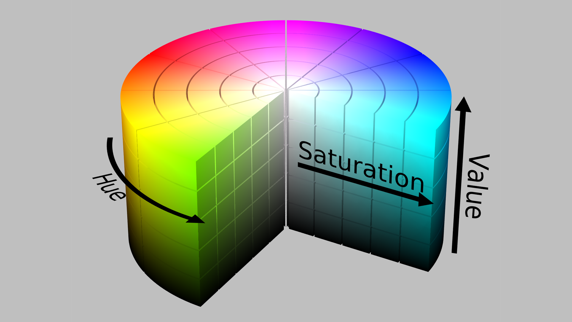
HSV is another way of representing the same colors, but this is on the other hand an acronym for Hue Saturation Value. This can be a preferred method to work with since it sometimes parametrizes the color more clearly: hue decides if the color is red, blue etc., saturation controls how much of that color is present compared to pure white light, and value controls the light intensity. If the value channel is zero, the LED is turned off, no matter what the two other channels are. HSV is similar to RGB with regards to the resolution for each channel.
Read more about FastLED’s HSV colors here.
LED Power Draw and USB Current Limit
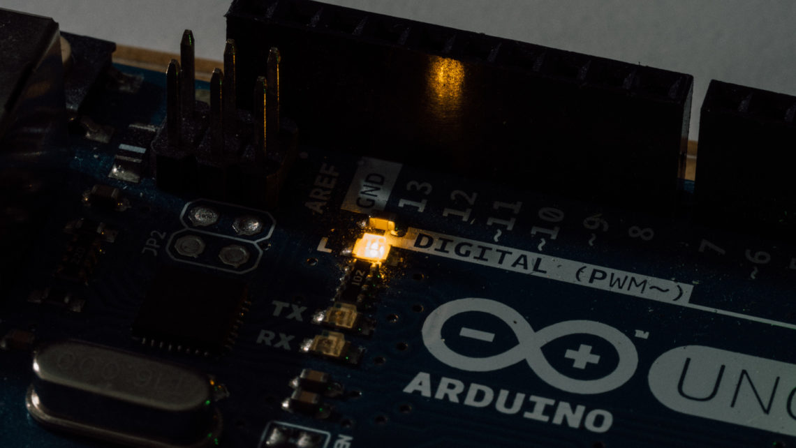
When connecting your Arduino to a USB port for power supply purposes you should never draw more than 500mA.
You should always check your LED strip and see how much power it may draw, which is often specified as watts per meter or just watts for the whole length of the strip. This number is for white color at full strength. You should also know how many LEDs per meter the strip has. Common numbers here are 30, 60 and 144 LEDs/m.
Let’s calculate how many mA each LED draws with two different examples:
Example 1
APA102
- 5 V
- 60 LEDs/m
- 18 W/m
We divide the power (18) by the LED density (60) and get 0.3 W/LED. We divide this by the voltage (5) and get 60 mA/LED.
Example 2
WS2812b
- 5 V
- 30 LEDs/m
- 45 W/strip
- 5 m strip length
We divide the power (45) by the length 5 and get 9 W/m. Then, we divide this number by the LED density (30) and get 0.3 W/LED. This is the same as in example 1, and since the voltage also is the same, we get 60 mA/LED.
What Does These Numbers Tell Us?
To stay below 500mA, which is important when using USB as power supply, you should not turn on more than 500/60 ≈ 8 LEDs with full white intensity with these LED strips.
If you only use one of the RGB channels, the LED will only draw approximately up to a third of the previously calculated value (20 mA). In this case we can set 500/20 = 25 LEDs at full red, green or blue intensity without exceeding the maximum USB current limit. In this case it’s easier to set RGB values instead of HSV values.
Gamma Correction
You should keep in mind that humans do not perceive the LED intensity linearly. We spot a much larger difference between 1-10 than between 246-255. This article explains this phenomenon.
The FastLED Library
This is an Arduino library that does all the low level stuff for you such that you only need to set which LEDs that need to be updated to which color value.
Chipset and Platform Support
A major advantage with this library is that it works with a long list of LED types (aka. chipsets):
- LPD8806
- WS2801
- SM16716
- P9813 – aka. Total Control Lighting
- APA102 – aka. SuperLED
- WS2811/WS2812/WS2812b – aka. NeoPixel
- TM1809/TM1804
- TM1803
- UCS1903/UCS1903B/UCS1904/UCS2903
- GW6205
- LPD1886
In addition to Arduino, this library works on several other platforms in the same category. Check out this page for more info.
Examples
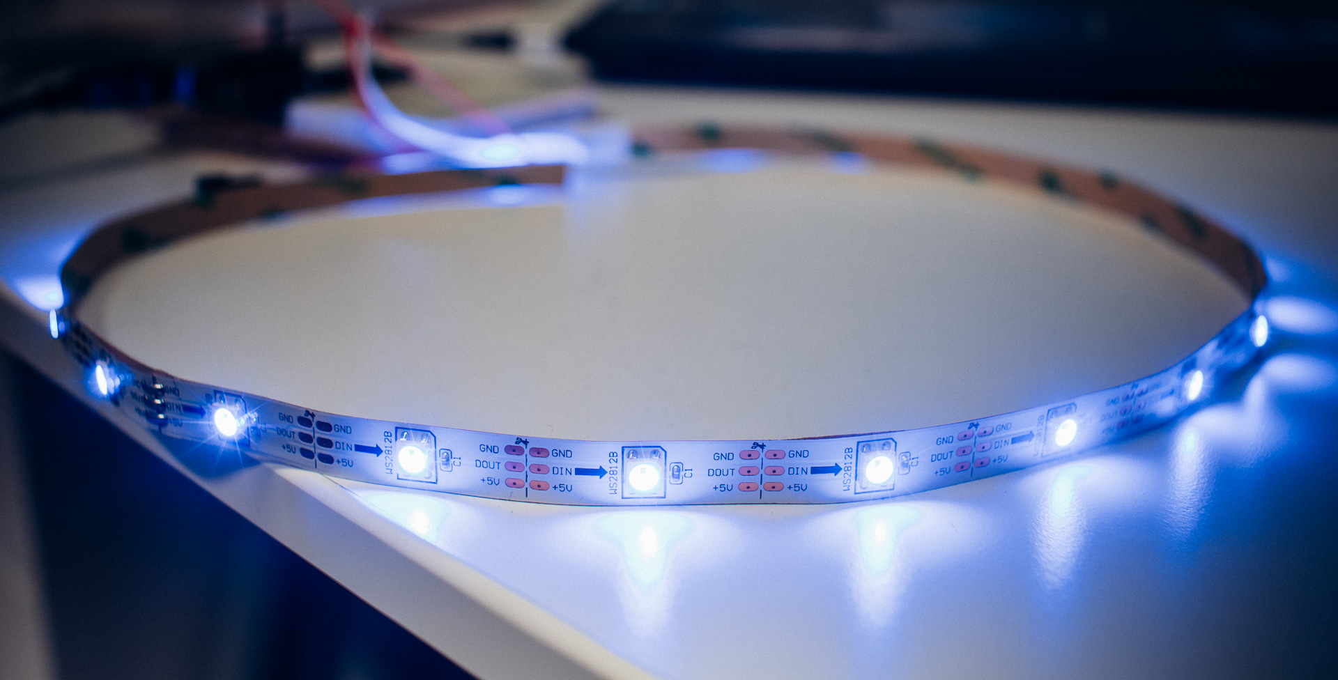
In the examples below we’re using a WS2812b LED strip with 22 LEDs.
Example 1
#include "FastLED.h"

// How many leds in your strip?
#define NUM_LEDS 22

#define DATA_PIN 5
//#define CLOCK_PIN 13

CRGB leds[NUM_LEDS];

void setup() {
	// Uncomment/edit one of the following lines for your leds arrangement.
	// FastLED.addLeds<TM1803, DATA_PIN, RGB>(leds, NUM_LEDS);
	// FastLED.addLeds<TM1804, DATA_PIN, RGB>(leds, NUM_LEDS);
	// FastLED.addLeds<TM1809, DATA_PIN, RGB>(leds, NUM_LEDS);
	// FastLED.addLeds<WS2811, DATA_PIN, RGB>(leds, NUM_LEDS);
	// FastLED.addLeds<WS2812, DATA_PIN, RGB>(leds, NUM_LEDS);
	FastLED.addLeds<WS2812B, DATA_PIN, RGB>(leds, NUM_LEDS);
	// FastLED.addLeds<NEOPIXEL, DATA_PIN>(leds, NUM_LEDS);
	// FastLED.addLeds<APA104, DATA_PIN, RGB>(leds, NUM_LEDS);
	// FastLED.addLeds<UCS1903, DATA_PIN, RGB>(leds, NUM_LEDS);
	// FastLED.addLeds<UCS1903B, DATA_PIN, RGB>(leds, NUM_LEDS);
	// FastLED.addLeds<GW6205, DATA_PIN, RGB>(leds, NUM_LEDS);
	// FastLED.addLeds<GW6205_400, DATA_PIN, RGB>(leds, NUM_LEDS);

	// FastLED.addLeds<WS2801, RGB>(leds, NUM_LEDS);
	// FastLED.addLeds<SM16716, RGB>(leds, NUM_LEDS);
	// FastLED.addLeds<LPD8806, RGB>(leds, NUM_LEDS);
	// FastLED.addLeds<P9813, RGB>(leds, NUM_LEDS);
	// FastLED.addLeds<APA102, RGB>(leds, NUM_LEDS);
	// FastLED.addLeds<DOTSTAR, RGB>(leds, NUM_LEDS);

	// FastLED.addLeds<WS2801, DATA_PIN, CLOCK_PIN, RGB>(leds, NUM_LEDS);
	// FastLED.addLeds<SM16716, DATA_PIN, CLOCK_PIN, RGB>(leds, NUM_LEDS);
	// FastLED.addLeds<LPD8806, DATA_PIN, CLOCK_PIN, RGB>(leds, NUM_LEDS);
	// FastLED.addLeds<P9813, DATA_PIN, CLOCK_PIN, RGB>(leds, NUM_LEDS);
	// FastLED.addLeds<APA102, DATA_PIN, CLOCK_PIN, RGB>(leds, NUM_LEDS);
	// FastLED.addLeds<DOTSTAR, DATA_PIN, CLOCK_PIN, RGB>(leds, NUM_LEDS);
}

void loop() {
	for(int i=0; i<NUM_LEDS; i++){
		leds[i] = CHSV(160, 255, 128);
		FastLED.show();
		delay(50);
		leds[i] = CHSV(0,0,0);
		FastLED.show();
	}
}
Most of these lines are commented out only to show what you need to include depending on your LED type. As you can see, we’ve uncommented the line with WS2812b since that is what we’re using. We’ve also commented out the CLOCK_PIN define since we don’t use a clock pin on this LED strip.
This code sets a LED to a blue color with 50% intensity and keeps it turned on for 50 ms before it turns it off and continues to the next LED on the strip until all the LEDs have had their turn, before starting all over again.
Notice the FastLED.show() function. This works sort of like a refresh function which sends the desired state to each LED. LEDs that haven’t had their state changed since last time the function was called will keep their last state. You don’t have to call this function for each LED that you want to change, you just call it when you want to refresh all your LEDs.
Example 2
#include "FastLED.h"

#define NUM_LEDS 22
#define DATA_PIN 5
#define TWO_HUNDRED_PI 628

CRGB leds[NUM_LEDS];

int element = 0;
int last_element = 0;

void setup() {
	FastLED.addLeds<WS2812B, DATA_PIN, RGB>(leds, NUM_LEDS);
}

void loop() {
	for(int i=0; i<TWO_HUNDRED_PI; i++){
		element = round((NUM_LEDS-1)/2*(sin(i/100.0)+1));
		leds[element].g = 64;
		FastLED.show();

		delay(1);

		if(element < last_element){
			leds[element].g = 0;
			FastLED.show();
		}

		last_element = element;
	}
}
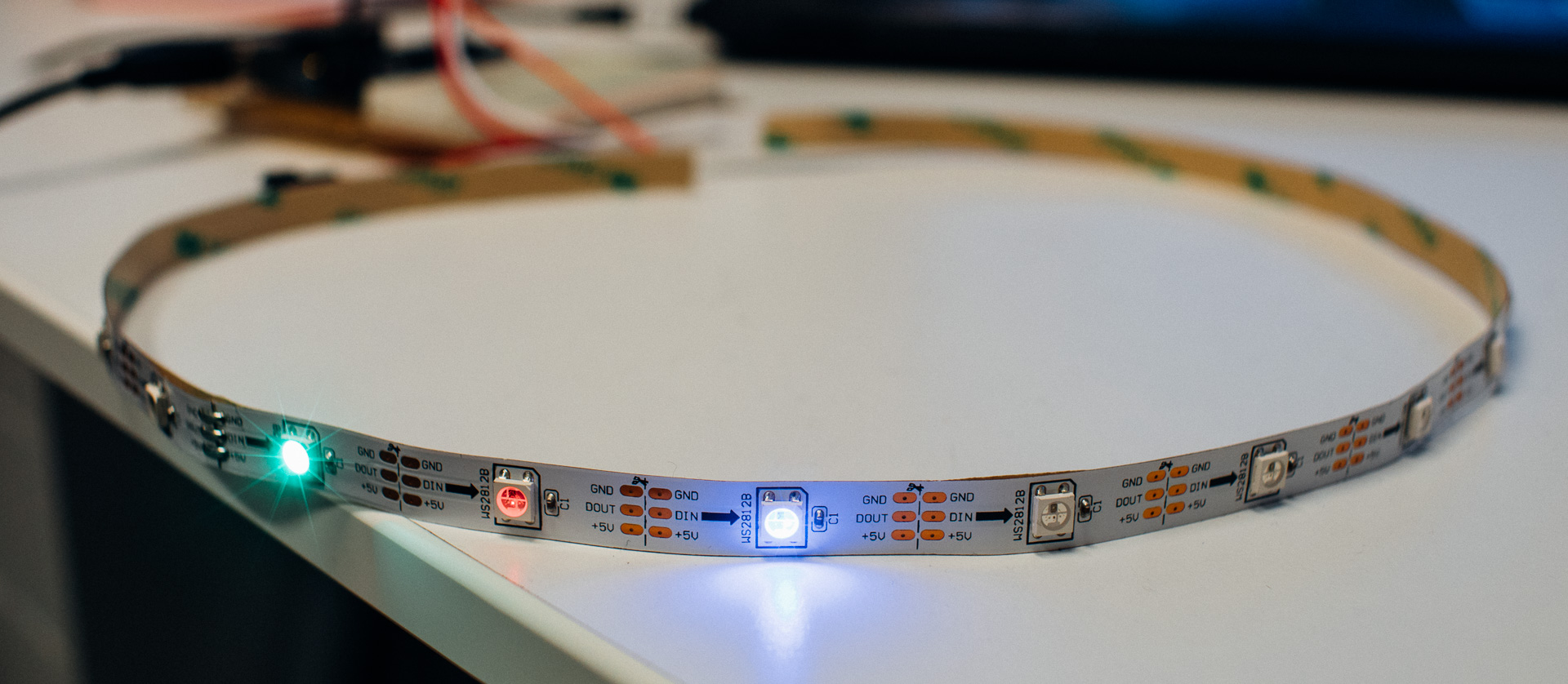
This code lights up all the LEDs one by one at 25% green intensity before shutting them off, one by one, everything in a sinewave pattern.
Example 3
In this last example we’ll do some LED fading.
#include "FastLED.h"

#define NUM_LEDS 22
#define DATA_PIN 5
#define TWO_HUNDRED_PI 628
#define TWO_THIRDS_PI 2.094

CRGB leds[NUM_LEDS];

int val1 = 0;
int val2 = 0;
int val3 = 0;

void setup() {
	FastLED.addLeds<WS2812B, DATA_PIN, RGB>(leds, NUM_LEDS);
}

void loop() {
	for(int i=0; i<TWO_HUNDRED_PI; i++){
		val1 = round(255/2.0*(sin(i/100.0)+1));
		val2 = round(255/2.0*(sin(i/100.0+TWO_THIRDS_PI)+1));
		val3 = round(255/2.0*(sin(i/100.0-TWO_THIRDS_PI)+1));

		leds[7] = CHSV(0, 255, val1);
		leds[8] = CHSV(96, 255, val2);
		leds[9] = CHSV(160, 255, val3);

		FastLED.show();

		delay(1);
	}
}
Here we fade three separate LEDs with three different colors up and down in a sinewave pattern. The fade periods are phase shifted by 60 degrees between each LED.
Summary
LEDs are some of the coolest things to tinker with in embedded systems and working with LEDs is super easy with Arduino and the FastLED library. The library has a lot more functions than we’ve used in these examples. Take a look at the documentation for a full overview.