Last year we wrote a blog post where we showed how to use parametric modelling to make a simple box. Someone commented that they would like to know how to make a triangle box as well. We thought it would be a fun exercise, so here’s how to make a triangle box!
We’re going to assume that you have read the previous post about parametric modelling in Fusion 360, which we mentioned above. There you will find basic info about parametric modelling and what you need to be aware of when working like this.
There are several types of triangles. This method allows you to create either an isosceles triangle box or an equiliteral triangle box. Making a box based on a right triangle shape isn’t more difficult, but you will need to draw the first sketch a bit different compared to the following method:
Step 1 – Parameters
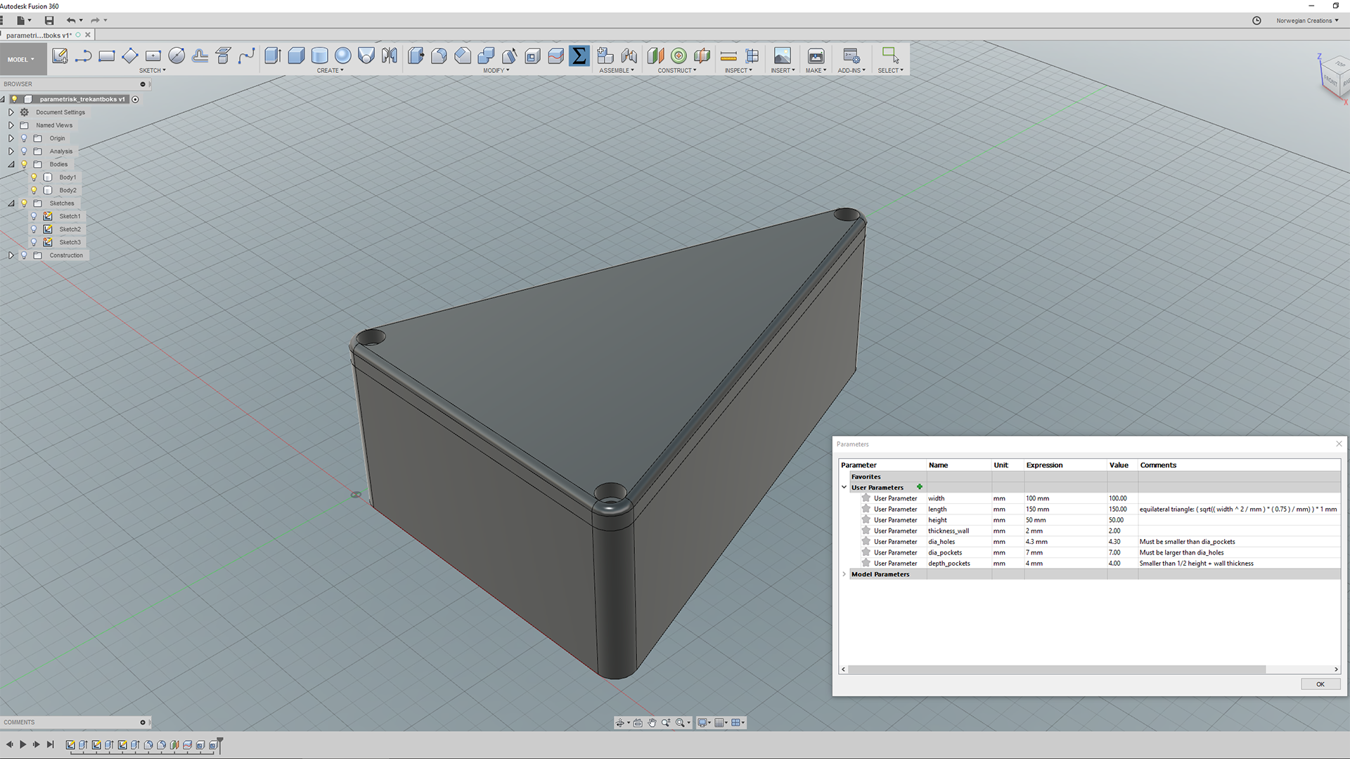
You’ll need to create the following list of parameters. You can of course choose your own values as long as they are within the constraints mentioned in the comments fields.
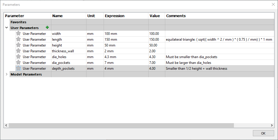
To make an equilateral triangle, enter the expression in the comment field of the length parameter. We derived this expression from the Pythagorean theorem. We need the /mm parts since Fusion 360 is very literal when it comes to units. By dividing by mm we get a unitless expression (required when using square root and such) before multiplying with 1 mm at the end.
Step 2 – Initial Sketch
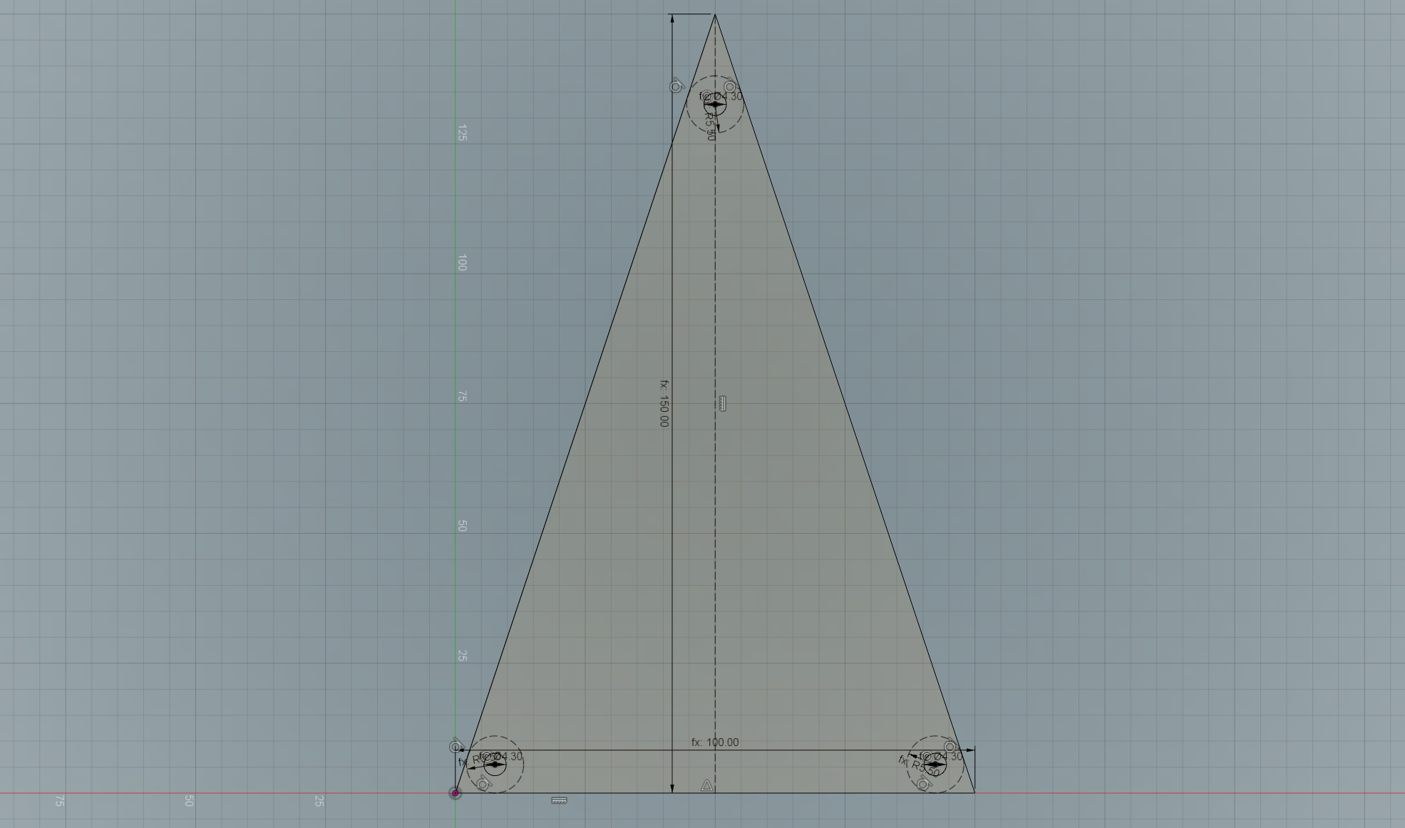
Start by creating a line with width length. Be sure to enter an angle (0 degrees in our case) as a constraint. Then create a line orthogonal to the first line starting from its midpoint with length length. Make this second line a construction line (select it and press x). Then draw lines between the lines’ endpoints to create a triangle.
Now create a circle near each corner. The purpose of these circles is just to find a center point for the holes and the pockets. Use the 2-Tangent Circle tool and select two of the outer lines before entering thickness_wall + dia_pockets/2 as radius. Make these three circles construction lines as well.
Lastly, create one center diameter circle in the center of each of the previously constructed circles with diameter dia_holes. Your sketch should now look like this:
Step 3 – Extrusion
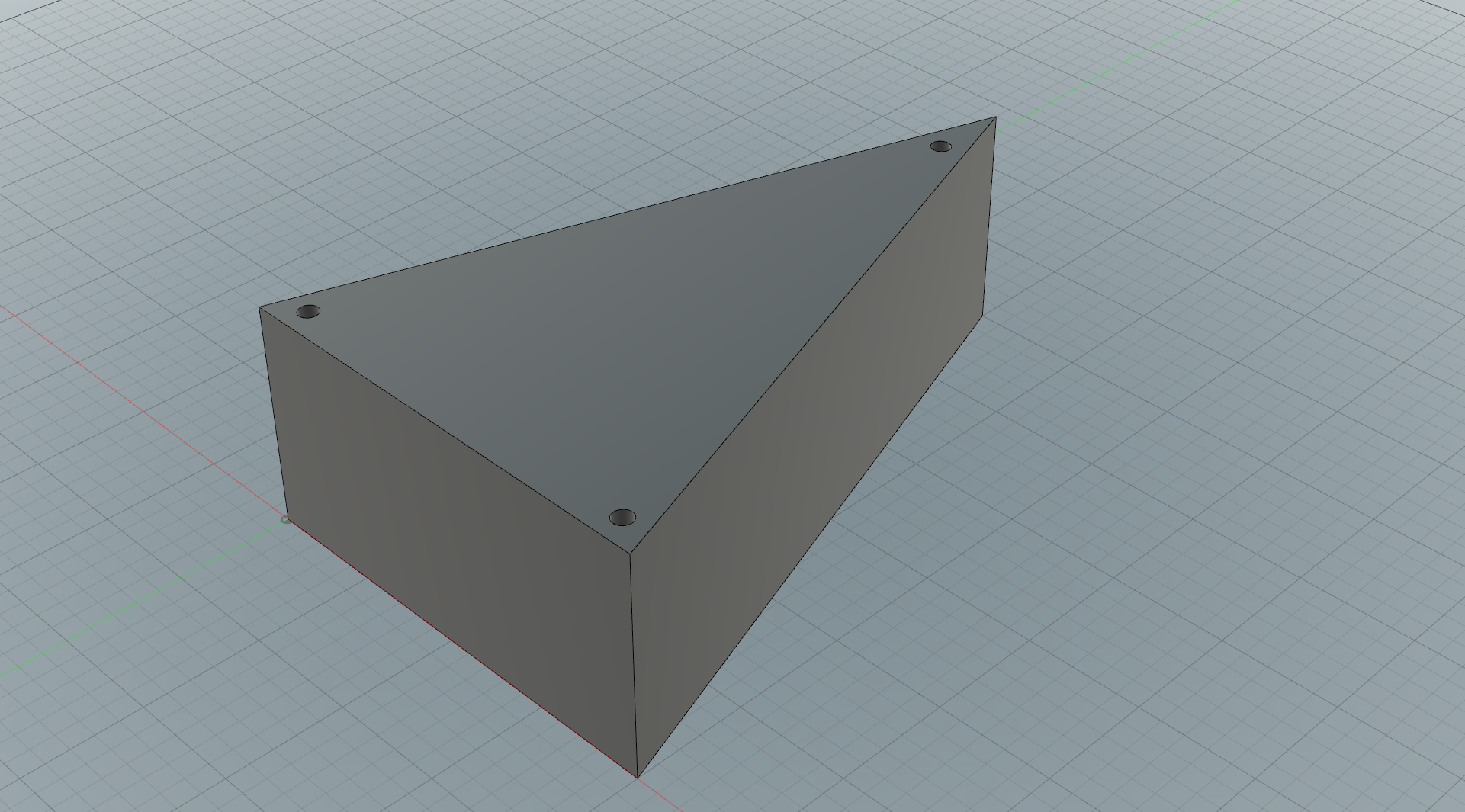
Extrude the main shape of the box with height amount, resulting in something like this:
Step 4 – Pockets
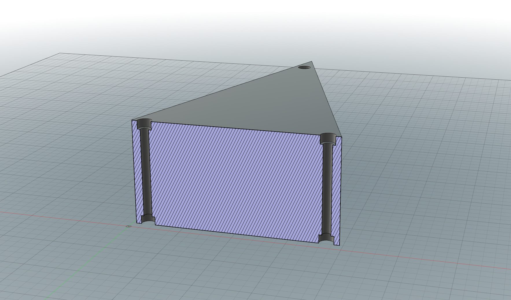
Create a new sketch on the top surface. Create three circles with center at the center of each hole and with diameter dia_pockets. Extrude these circles such that they cut into the model with an amount of depth_pockets.
Then project the top surface onto the bottom surface and do the same extrusion operation there.
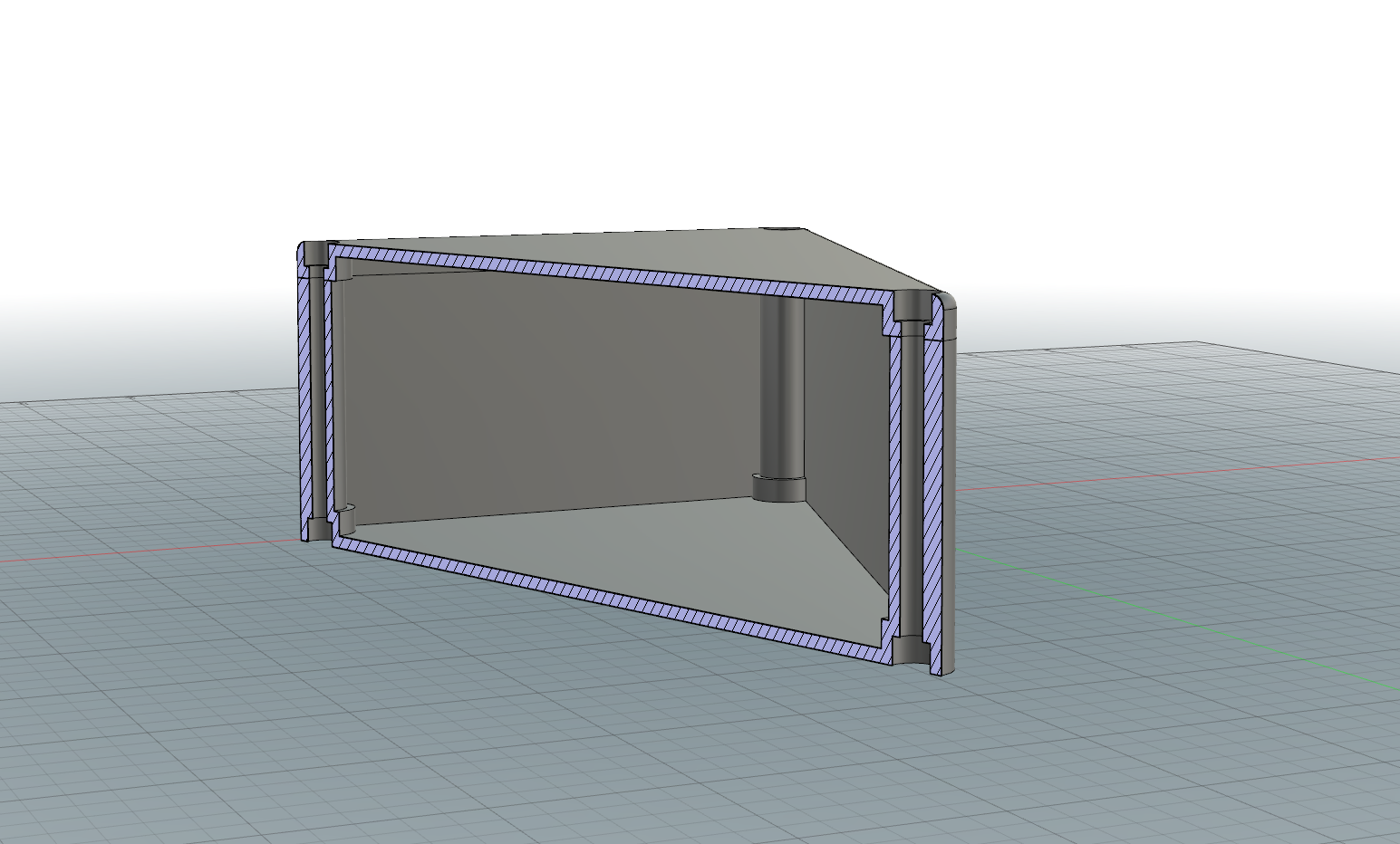
This should result in the following (displayed with a section analysis to properly show the pockets):
Step 5 – Filleting
This step is not necessary, but the box will look nicer with a bit of fillets. One way you can do this is to first fillet the three corners with radius equal to thickness_wall + dia_pockets/2. This way we will get a constant thickness around the holes and pockets. Then fillet the top edge with radius equal to thickness_wall.
This will result in a model looking like this:
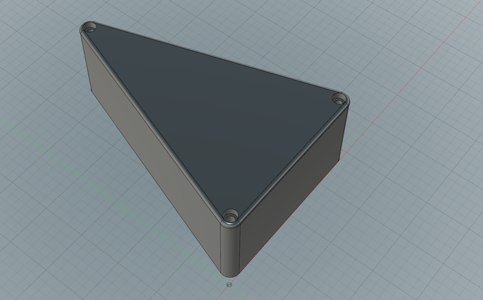
Step 6 – Split and Shell
Create an offset plane from the top face with an offset downwards equal to depth_pockets + thickness_wall. Use that plane to split the body.
Then do two shell operations by selecting the “inner” faces of each of the two bodies (the top face of the bottom part and the bottom face of the top part) with wall thickness equal to thickness_wall.
And that’s it! You now have a triangle-shaped box.