As you might be aware of, we in NC use Autodesk Fusion 360 daily. Fusion 360 fully supports parametric modelling, which is the topic of this post. We’ll explain very briefly what parametric modelling is as well as go through an example where we use this method to create a generic 3D printer-friendly box.
Even if you’re not that interested in parametric modelling, but want to know more about working in Fusion 360, you might find this post interesting since we use many different tools in the example below.
What is Parametric Modelling?
Parametric modelling is a method where you use parameters to set the dimensions of part or all of your model. Big whoop, you might say. The cool part is that after your model is complete, and given that everything is in order, you can go back and change the parameters. The model will then change accordingly while still keeping its integrity intact.
This method is however not suited for every project. If the model becomes too artsy or too comlex you might quickly run into troubles. But if your model is simple and/or geometric, parametric modelling might be the way to go. We’ll continue this discussion in the bottom chapter.
The Box
We like examples, and this whole post will revolve around one single example where we’ll model a generic box using only parameters for all dimensions. It will have a bottom (box) part and a top (lid) part. Holes will run through both parts with pockets in both ends for bolt head and nut so that they don’t exceed the outer dimensions of the box.
The timeline at the bottom of the Fusion 360 screen should be on by default. If you’ve turned it off in the past you need to turn it on again (right click on the root component and select Capture Design History).
Let’s jump right into it!
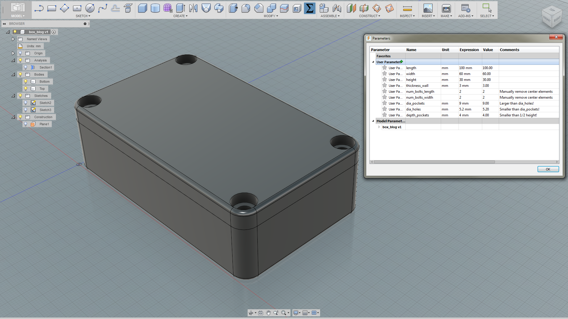
Step 1: Setting the Parameters
Under the Modify tab you’ll find a button that’s called Change Parameters. In the subsequent window you’ll define the parameters you want to use.
Press the green ‘+’ button to add parameters. Notice that the num_bolts_… parameters have no units. This is important. When adding parameters you can specify units from a large list.
We’ve added some comments to some of the parameters to remember a couple of things. Just notes to self.
Step 2: Making the Box
Use the box tool and enter the appropriate parameters in the dimension fields. Fusion 360 has a handy autocomplete function which saves you from typing the full parameter names.
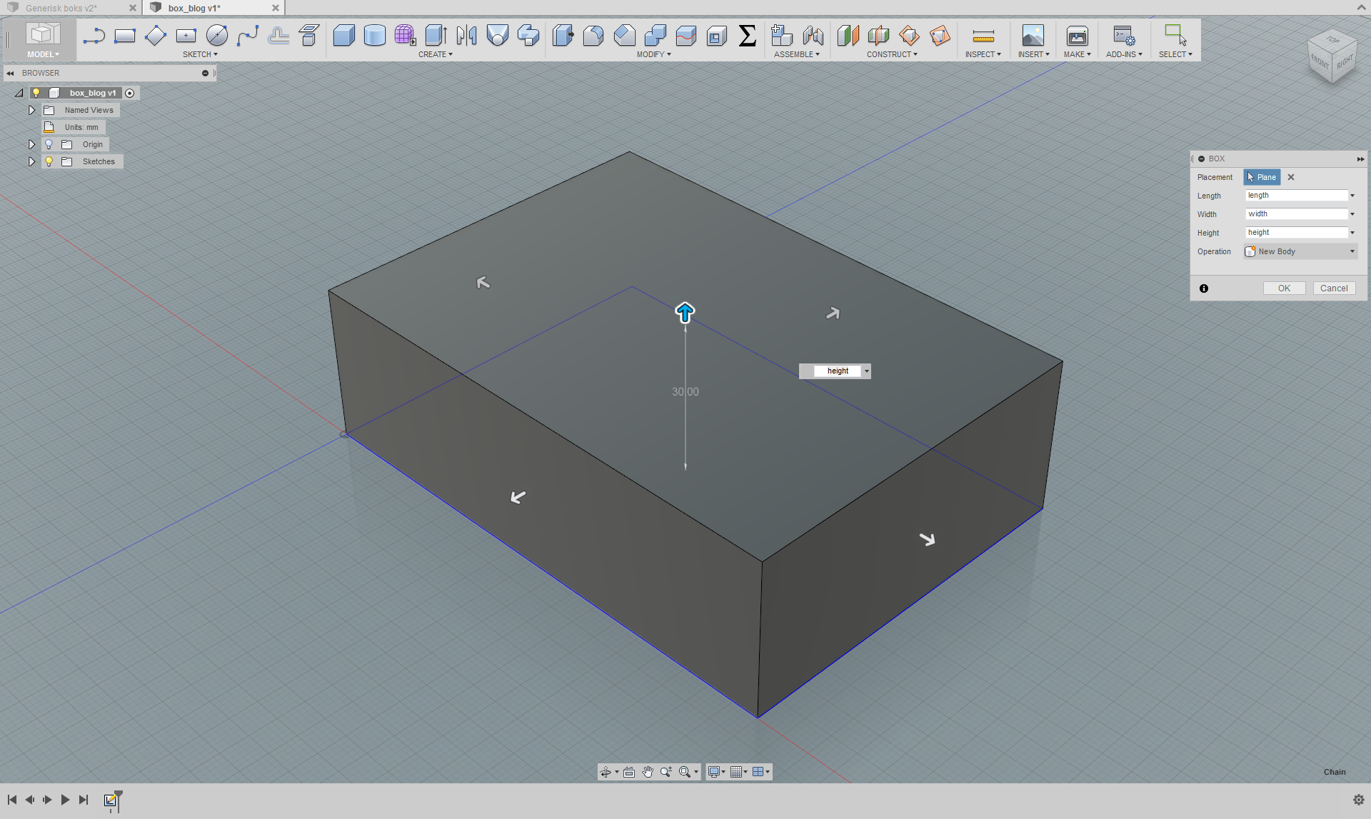
Make sure these parameters are displayed in the box to the right in the image above!
Step 3: Sketch #1
Now create a sketch on the top side of the box. Create a rectangle starting from a corner where each side is the following expression: (dia_pockets + thickness_wall ) / 2. Optional: make this square a construction object so that it becomes dotted orange instead of solid blue.
Now, in the square corner closest to the sketch center create two center diameter circles with dimensions dia_holes and dia_pockets, respectively.
If you double click on the dimensions in the sketch you can modify the expression.
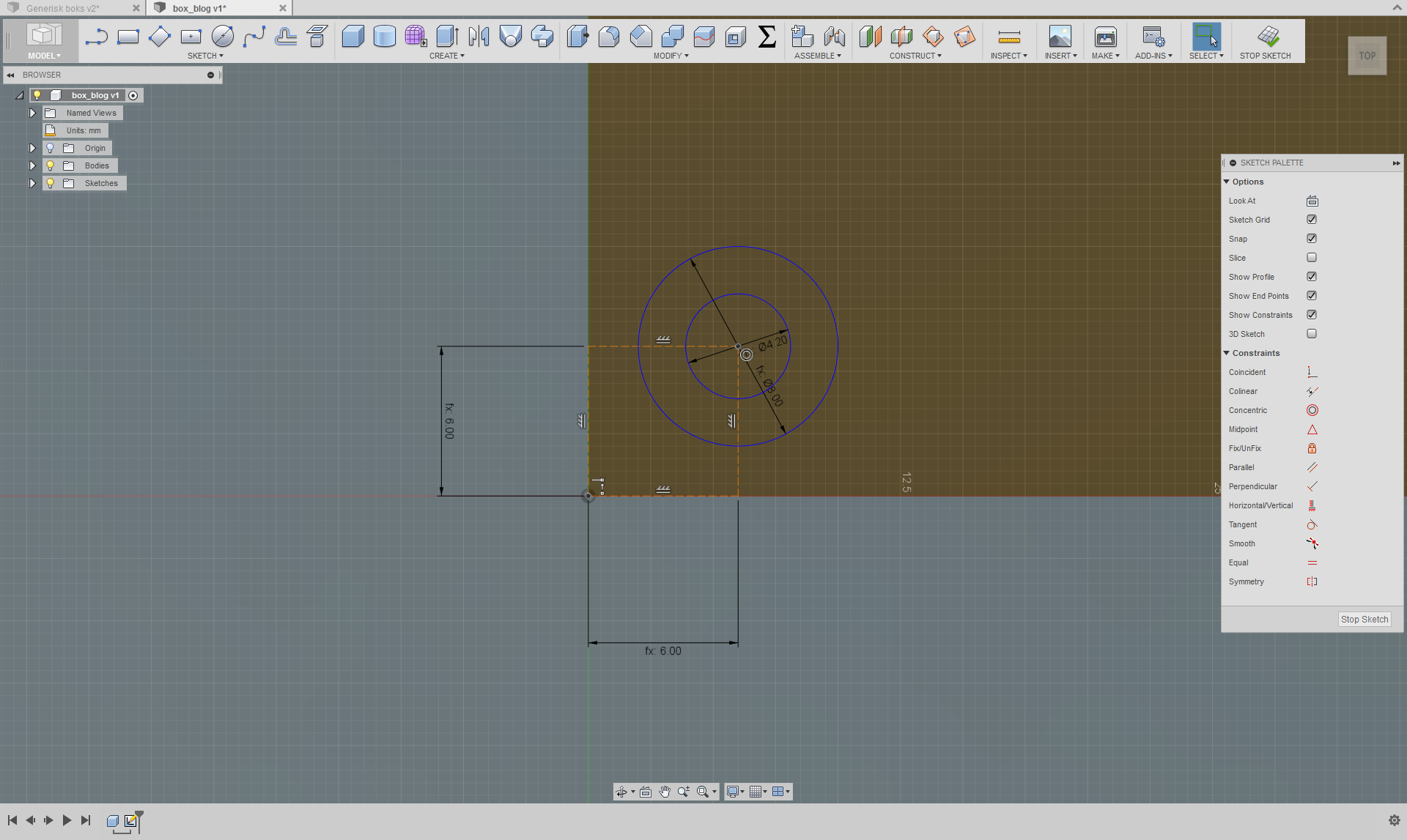
With these expressions we’re making sure that the holes and pockets will position themselves apropriately relative to the corners/edges even if we change the dimensions later.
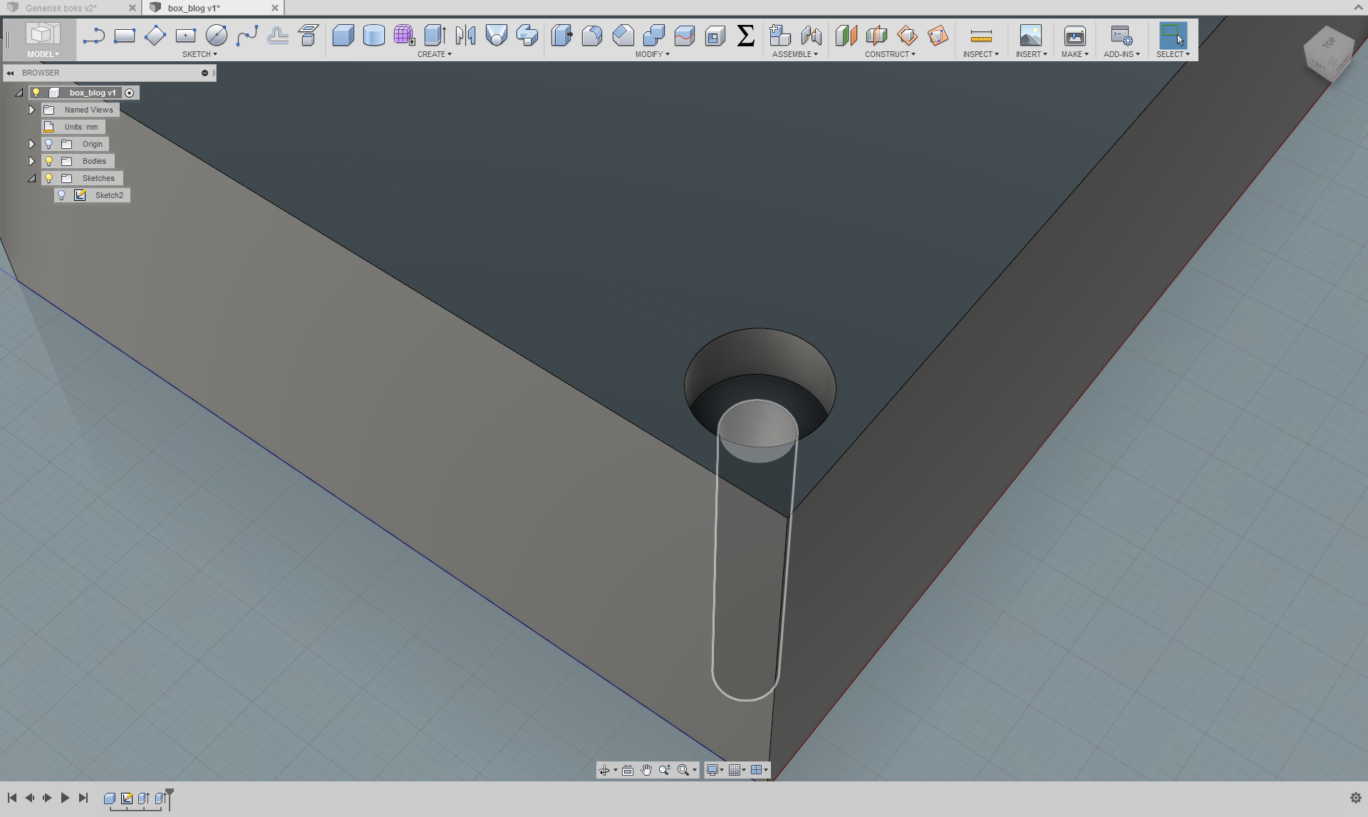
Step 4: Extrude Pockets and Holes
Extrude the two circles we made. The smallest can be extruded as -height and the largest can be extruded as -depth_pockets.
Step 5: Repeat for Bottom Side
We’re going to the same thing on the bottom side, except that we don’t have to draw the rectangle or worry about the hole. The only important thing here is the pocket.
Create a sketch on the bottom side of the box and create a center diameter circle in the center of the hole with the expression dia_pockets. Extrude this new sketch profile with the expression -depth_pockets.
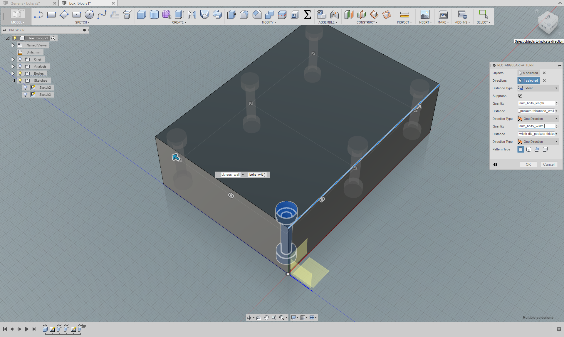
Step 6: Duplicate Holes and Pockets
Use the Rectangular Pattern tool under the Create tab. Select the faces relevant to the two pockets and the hole (5 faces in total). For direction just select one of the edges of the box.
First use the arrows to drag the pattern out a bit and to see what the pattern tool defines as the two axes. Then enter num_bolts_length and num_bolts_width in the appropriate Quantity fields.
In the Distance fields enter length – dia_pockets – thickness_wall and width – dia_pockets – thickness_wall. These parameters must go in the appropriate fields so that the actual axes coincides with the names (width/length).
If both Quantity fields are larger than two you will get one or more elements in the center. These can be manually removed by unchecking the checkboxes in the graphical view for each element you want to remove. If you then change the quantity parameters later you will most likely have to re-edit this to keep the ones you want to keep.
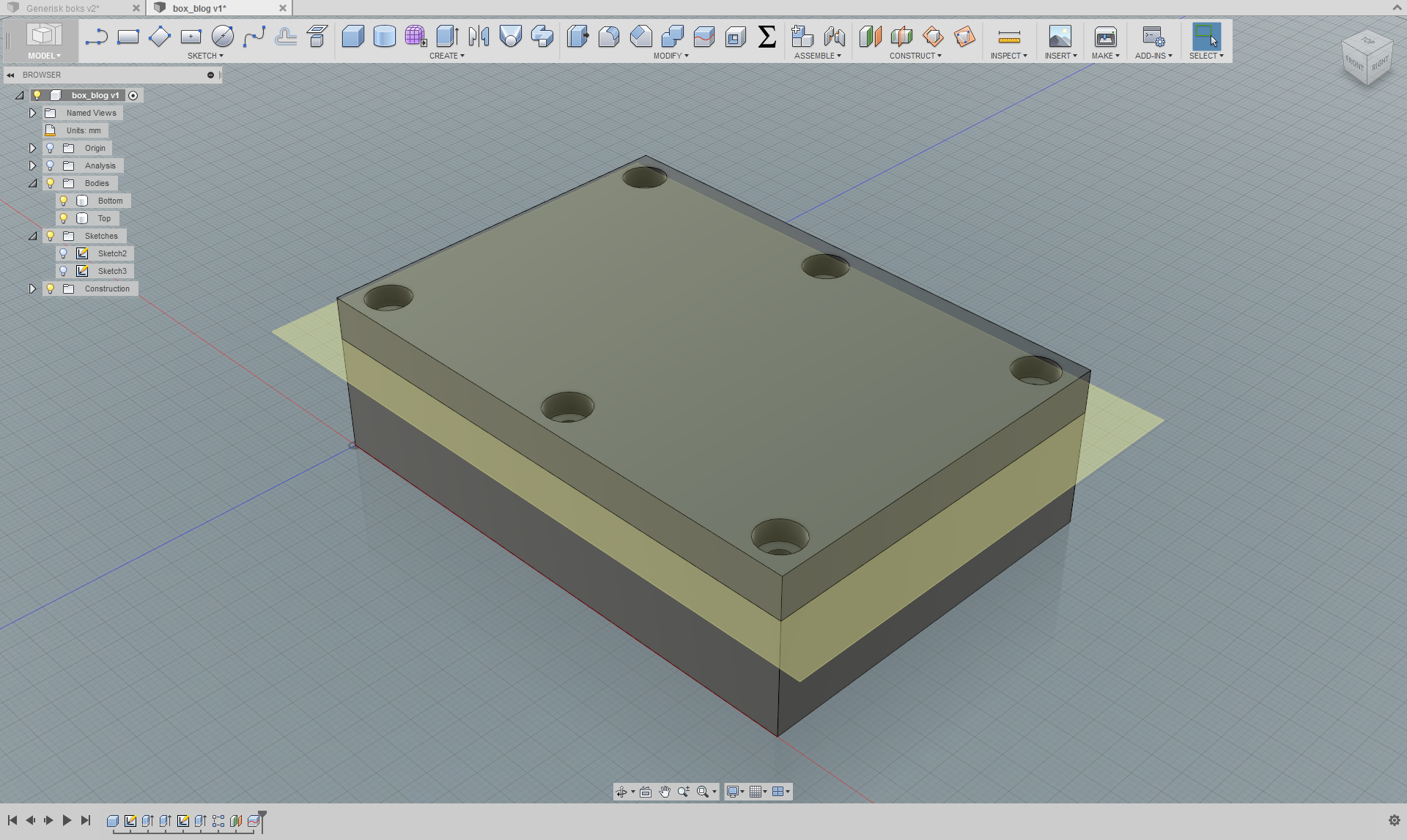
Step 7: Seperate Box and Lid
In the Construct tab select Offset Plane and select the top face of the box. In the distance field enter -depth_pockets – thickness_wall. If you decide to have deep pockets and/or thick walls, the lid height will compensate for that to maintain the model integrity.
Then, under the modify tab, use the Split Body tool. We only have one body, so select that. For splitting tool, select the plane we just created.
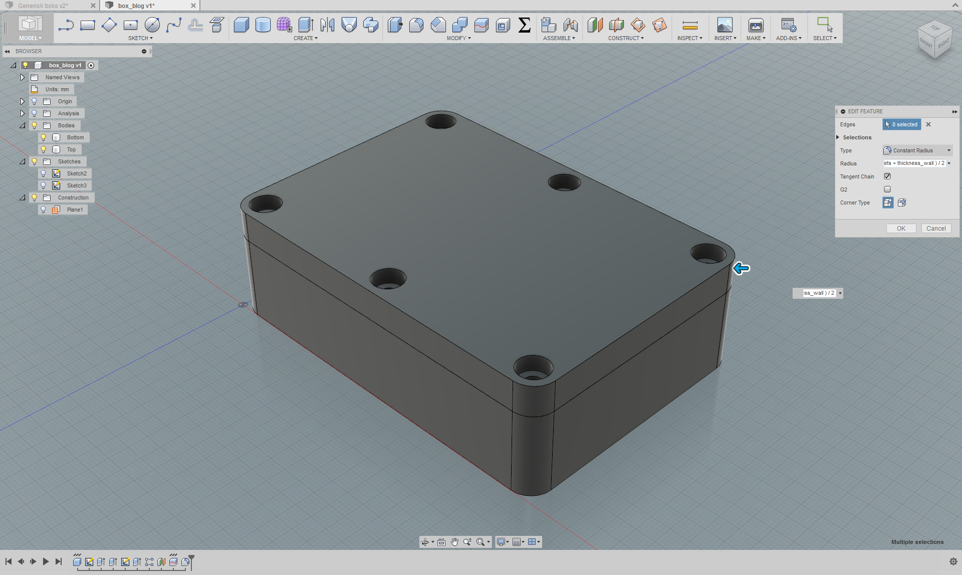
Step 8: Fillet #1
Use the Fillet tool and select all the vertical corner edges for both the top and the bottom body (8 edges in total). In the Radius field enter (dia_pockets + thickness_wall) / 2. With this expression we will get a nice constant wall around the pockets equal to half the wall thickness parameter.
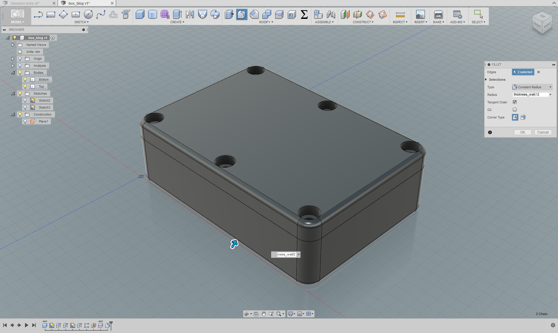
Step 9: Fillet #2
Now use the fillet tool on the top edge and the bottom edge and enter thickness_wall / 2 in the Radius field.
Step 10: Making the Box Less Like a Brick and More Like a Box
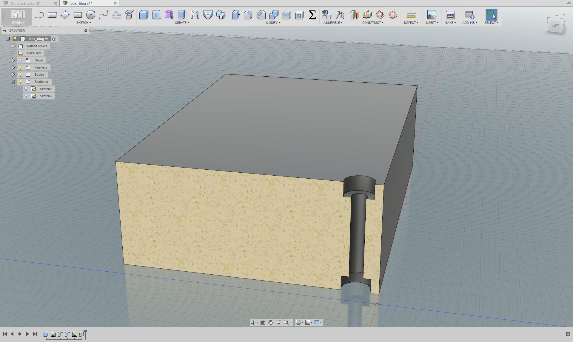
Under the Modify tab you’ll find the cool Shell tool. Hide the Lid and select the top face of the bottom body. In the Inside Thickness field enter thickness_wall.
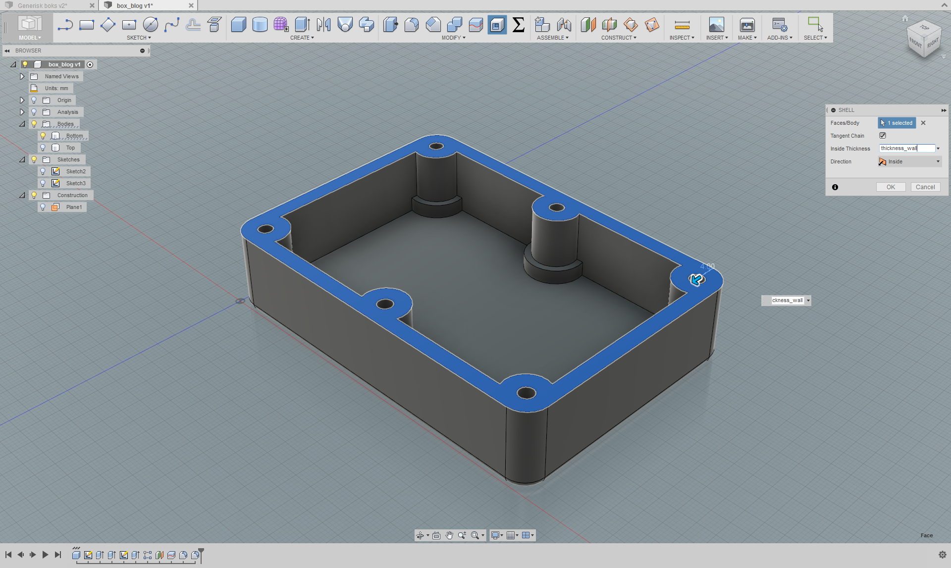
Now do the same for the underside of the lid!
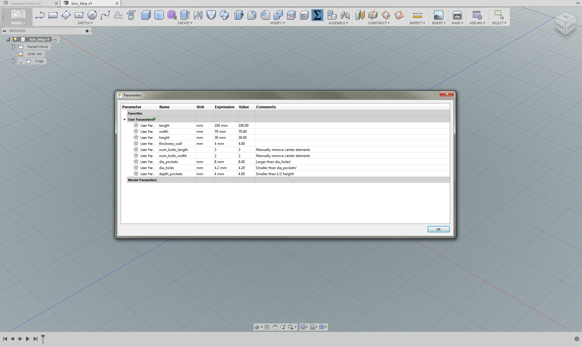
Step 11: Tweak Your Parameters
Revisit the Change Parameters window and modify the parameters as you see fit. If you’ve done everything right, the model will not break when tweaking the parameters within the constraints specified in the comments (and other obvious constraints).
Pitfalls and Tips
- The order of which you do things parametrically has a lot to say, so plan ahead.
- If you mess with parametric sketching, make sure you have your constraints in order.
- If the number of faces in a sketch or on a body changes due to a parameter change before an extrude, or any other face-based tool, the model might break or not behave the way you want.
- Tip: always play with relevant parameters when adding features to your model. This way you will detect any issues with your model (constraints etc.) early, so that they’re easy to fix.
- Tip: double click the icons in the timeline at the bottom to edit features. If you make a change in one feature it might have serious consequences for later dependent features, so stay frosty.
Final Words
Parametric modelling can be very useful in situations like in this example where you have a generic, simple and geometric design. Maybe you want to re-use the design for multiple projects with different dimensions without starting from scratch each time? Or maybe you’re waiting for the exact dimensions from someone else and would like to start the design right away? Going back to alter the dimensions without using parametric modelling CAN be a hassle, so using it can save you a lot of trouble. And remember: not EVERY dimension has to be parametric.
Know what you’re going to make, plan ahead and decide if the extra time invested into making a model parametric is worth it. It quite possibly might be.
If you want to read another tutorial about parametric modelling in Fusion 360, consider taking a look at this blog post.