We like to create custom stuff for our office. Previously we’ve made our own lamps as well as an “embedded-desk” with custom lighting.
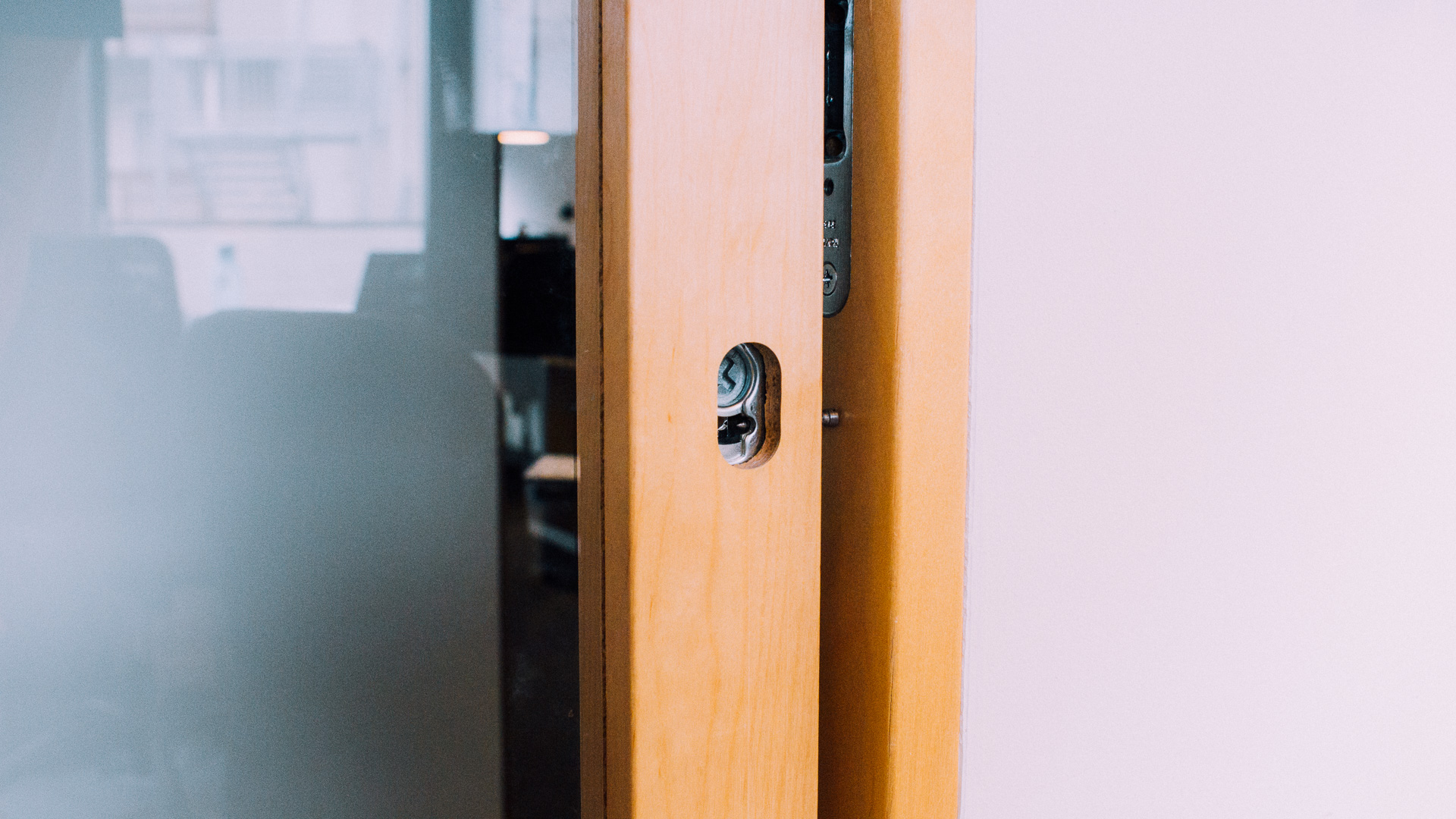
The goal for our next office project is to make it possible for us to lock and unlock our office door by using RFID access cards instead of a regular key. This post will go through the design elements only since we haven’t actually started building it yet.
However, at a later stage we’ll write several follow-up posts where we’ll talk about things like the electronics, the building process all the way to finished product and finally how it turned out in the end.
The Actuator
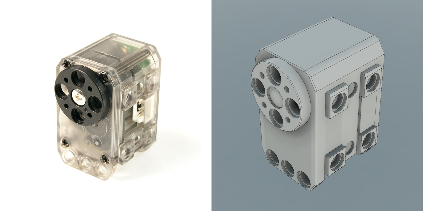
There are multiple types of actuators which can work in an application like this (servos, stepper motors, solenoids, pneumatics etc.). We had some interesting servos lying around from Robotis called Dynamixel XL-320 that we’d like to properly test, so that became the actuator of choice. This servo provides feedback on several parameters including position, load and temperature, and is a very sturdy, accurate and suitable servo in general.
The manufacturer has developed a custom communication protcol (Dynamixel SDK), so it is a bit more hassle to control these servos than your everyday RC-servos which just take PWM-signals. But once you have these up and running it’s definitely worth it!
The Structural Platform
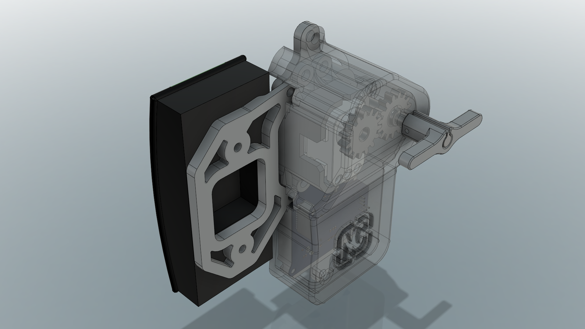
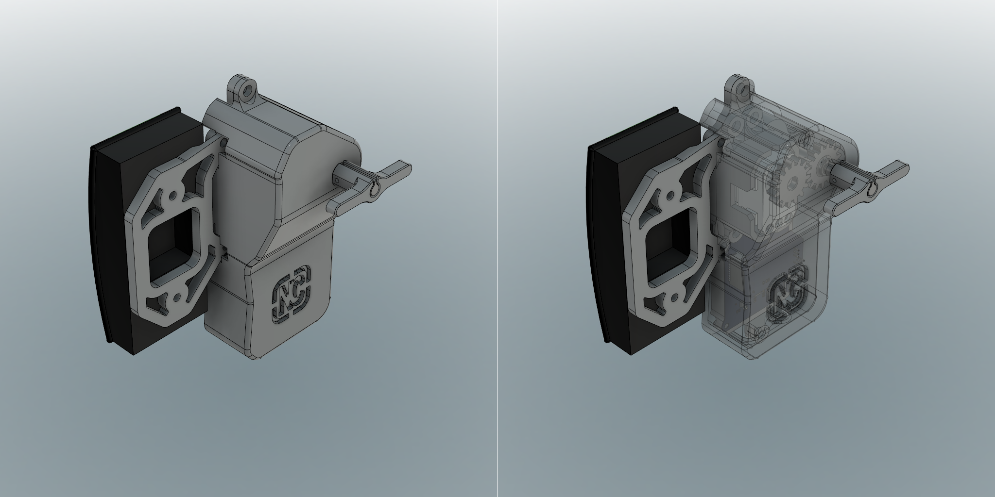
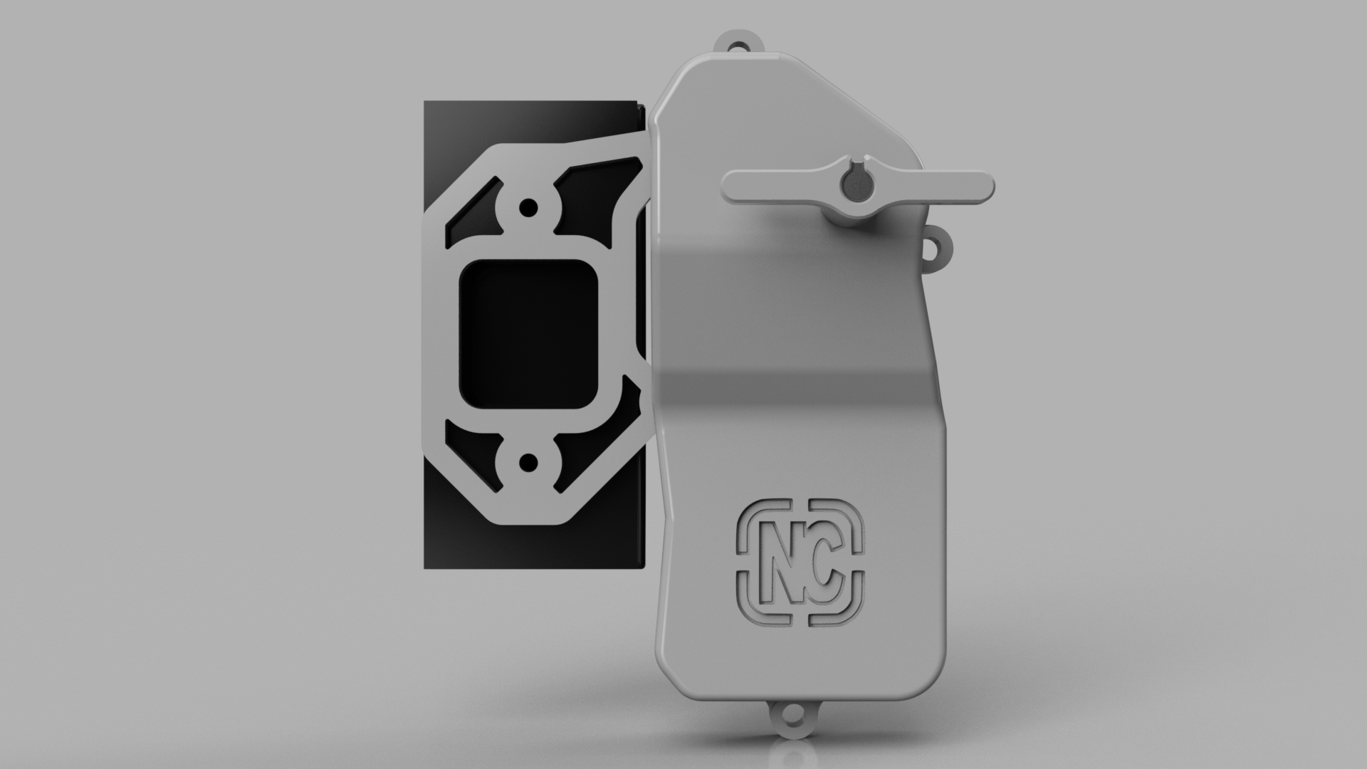
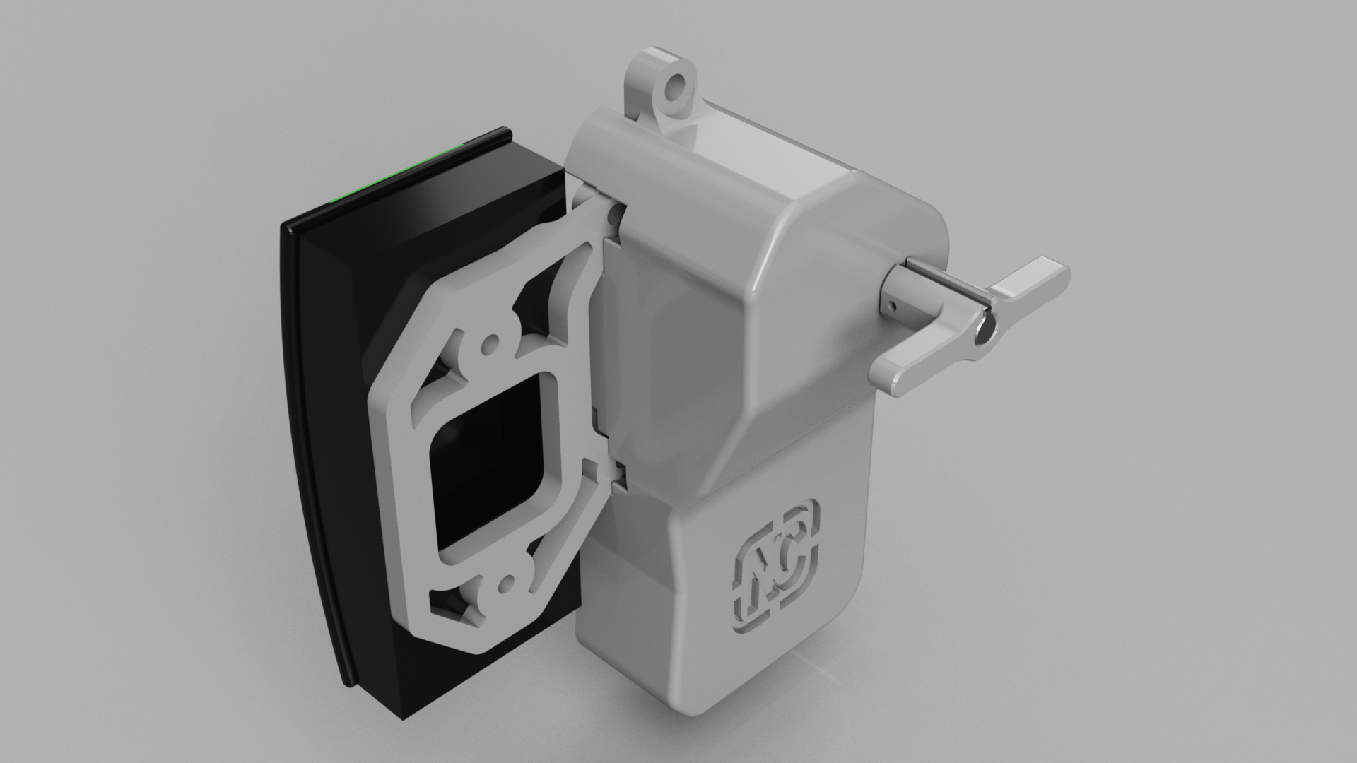
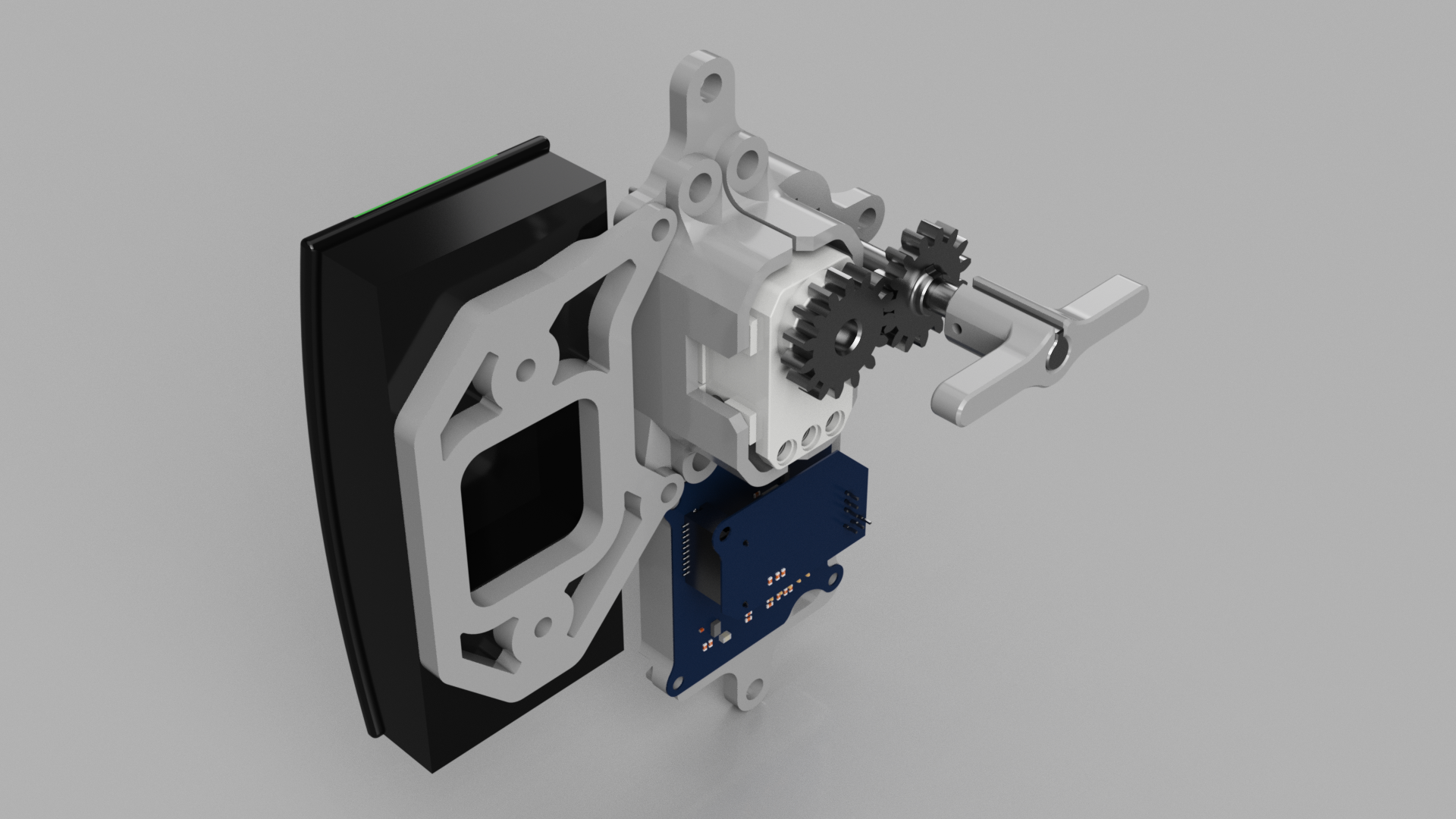
We needed something to attach everything to, some kind of structural platform. We also needed to mimic and replace the already existing cylinder in the door. So we brought out the calipers and started measuring (these things are rarely open source). Part of the platform will fit into the hole where the cylinder used to be and the remaining area will rest flat on the door.
We also needed a bracket to the card reader. This will be attached to the main platforlm such that we will gain access to the card reader from the outside through a glass window in the door.
Both of these parts were designed such that it is possible to print them on a tradtional FDM 3D printer with a flat surface and no unmanageable overhangs (we don’t like using supports).
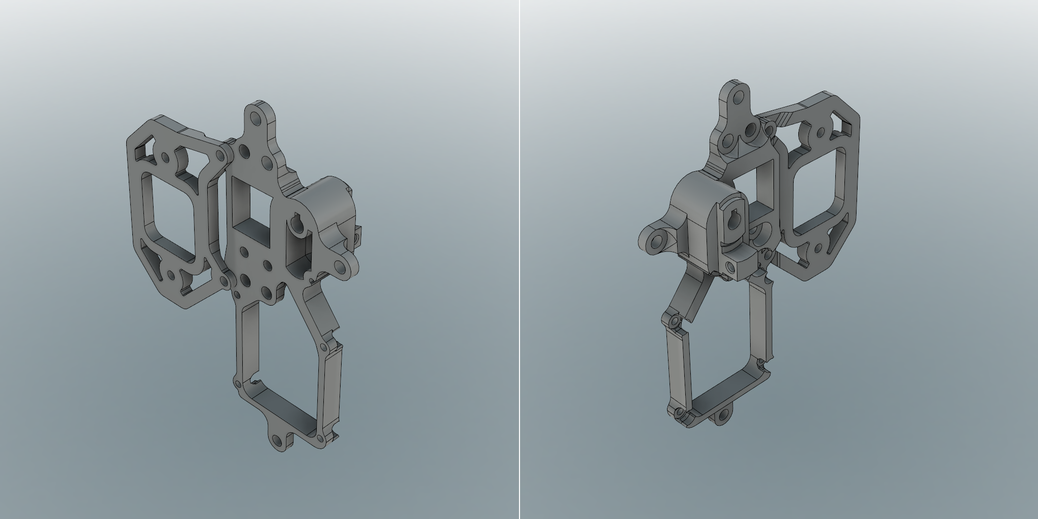
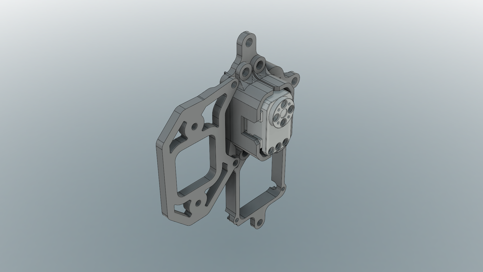
Attaching the Servo
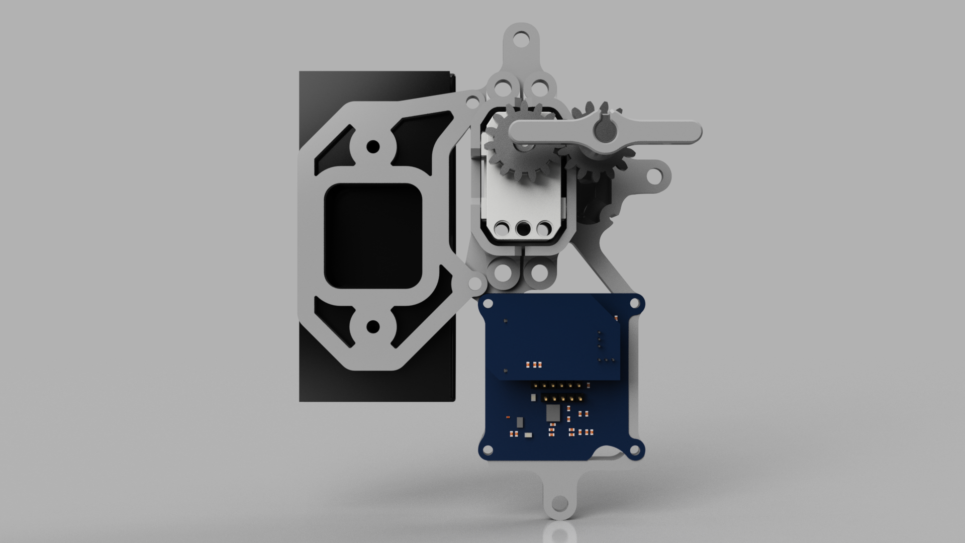
In addition to fasten the servo directly to the platform (only possible on one side) we made a couple of brackets to keep it properly in place. The brackets have a few pegs that fit into the holes on the side of the servo casing. We’ve also made sure we can reach one of the connectors on the sides with a cable.
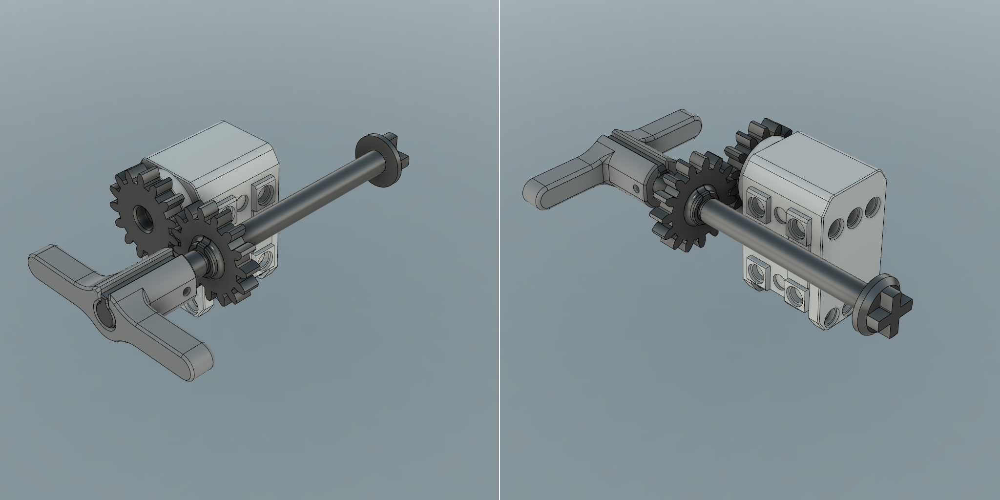
The Drivetrain
The rotational axis on the lock itself is parallel, but translationally shifted from the servo’s axis. To connect these two axes we use two evenly sized custom designed cogs.
While the static part of the cylinder is replaced by the main platform, the rotational part is replaced by the end of a rod (see the x-shaped extrusion in the right image below).
The servo cog is fastened to the permanently attached servo hub while the cog on the shaft is kept in place using two E type circlips.
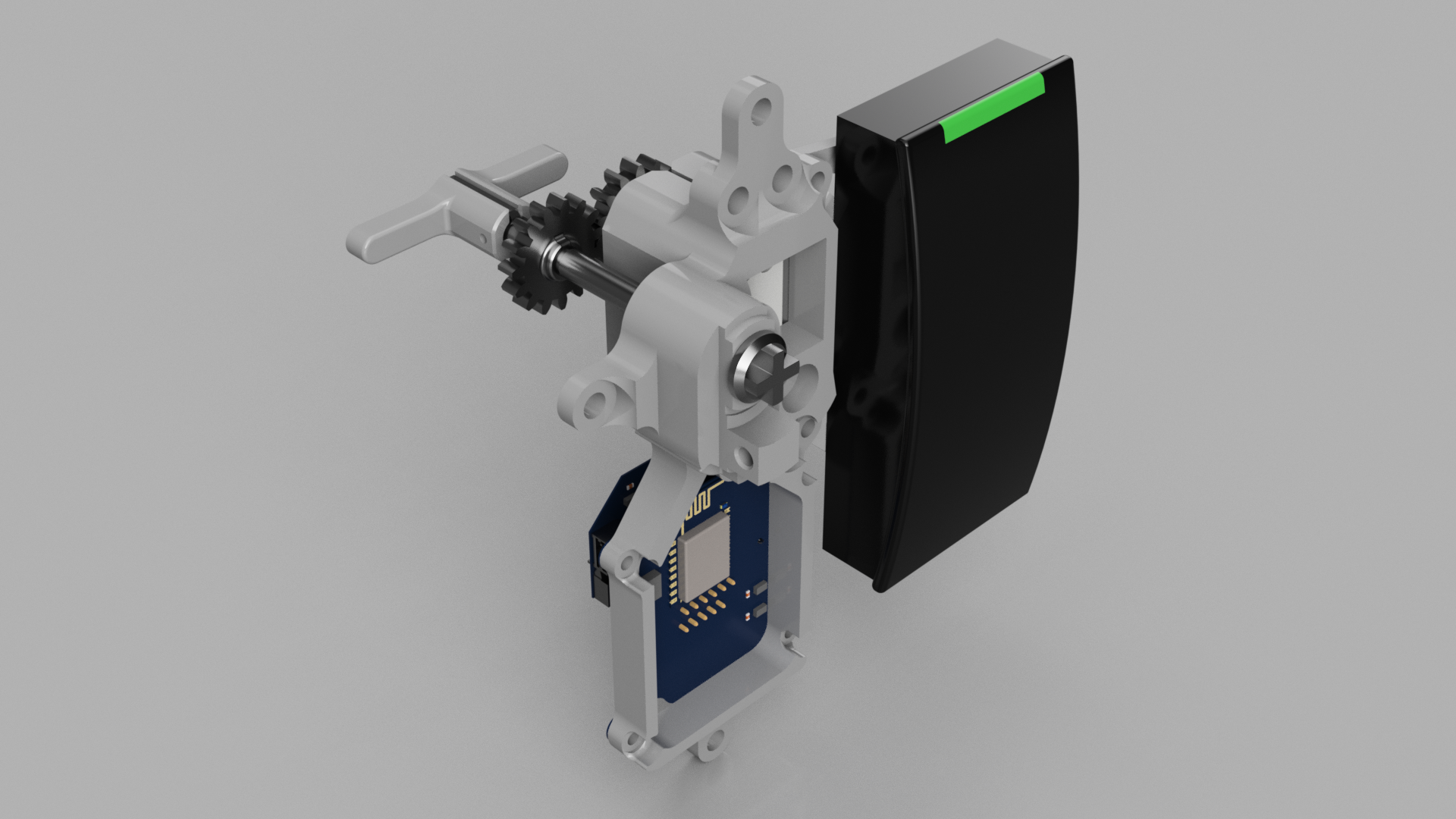
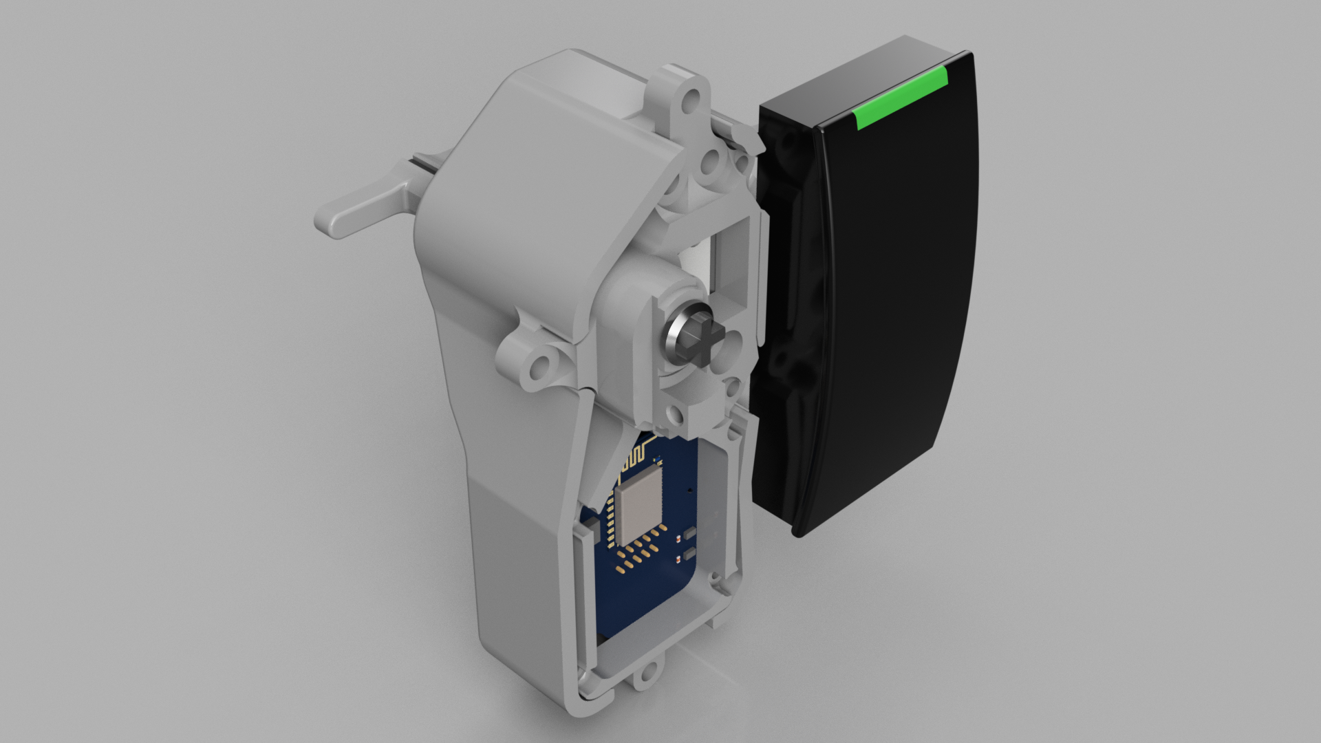
We also need a way to easily and manually lock/unlock the door from the inside as before as a backup solution, so we modelled a handle on the shaft which can be used to manually override the servo. This handle is fastened using an M2 bolt that penetrates the shaft. We also have room for a hose clamp if necessary.
The handle is possible to print in an FDM-printer, but the cogs and the shaft must be printed in a more professional printer, preferably in metal (which is possible at for instance Shapeways).
The Electronics
The electronics for this project will be the subject in a whole seperate blog post in the future, but we’ll give a brief overview here.
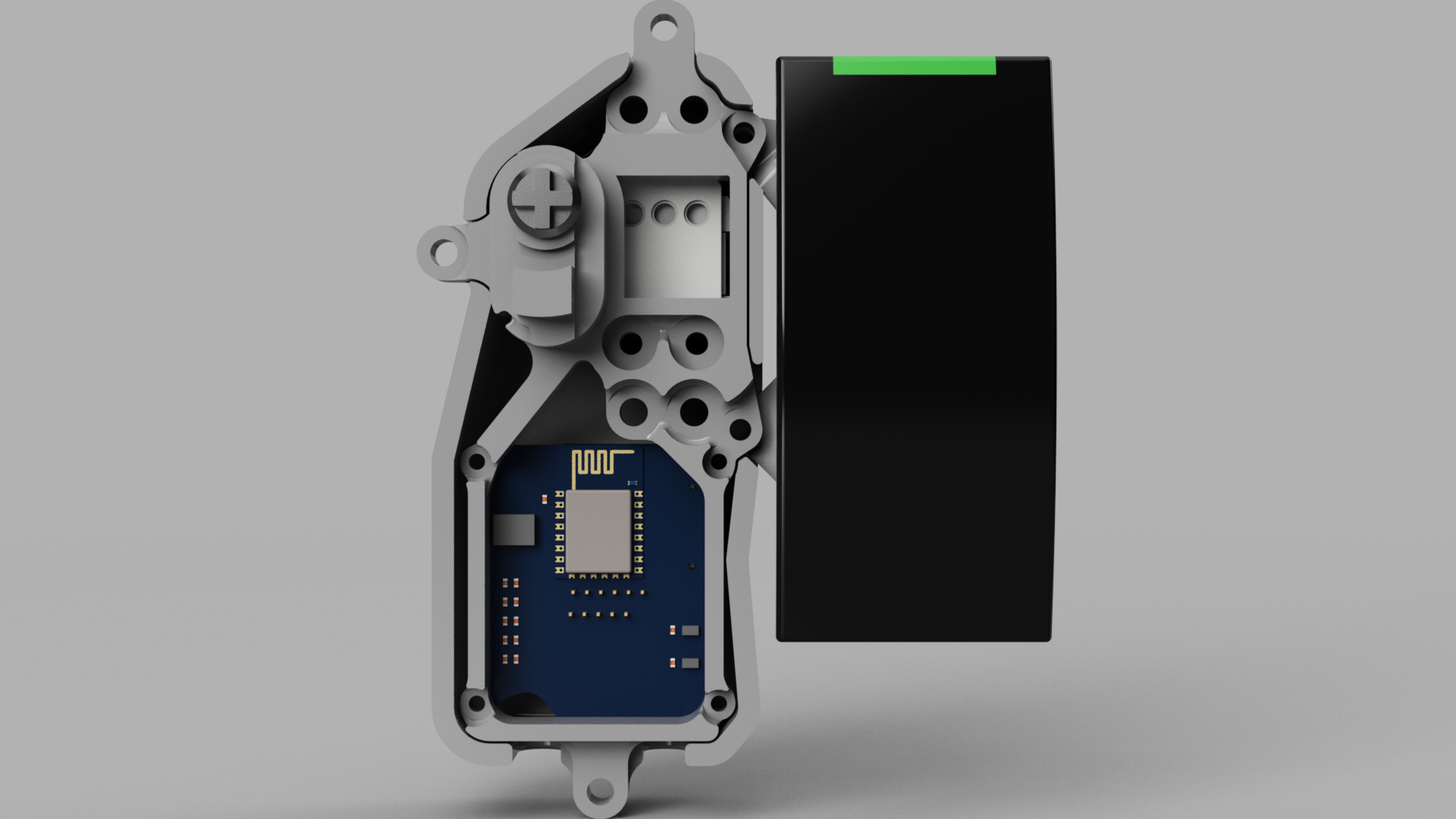
We have designed a custom multi-purpose modular PCB system from scratch with a main board and application-specific shields. The main board has a WiFi Module for communication while the shield in this case handles the servo control. The PCB is mounted on the lower part of the main platform, below the drivetrain.
Another feature we’ve included is to sense when the door is shut and cleared for locking.
We use a similar card reader as the one attached to our embedded-desk.
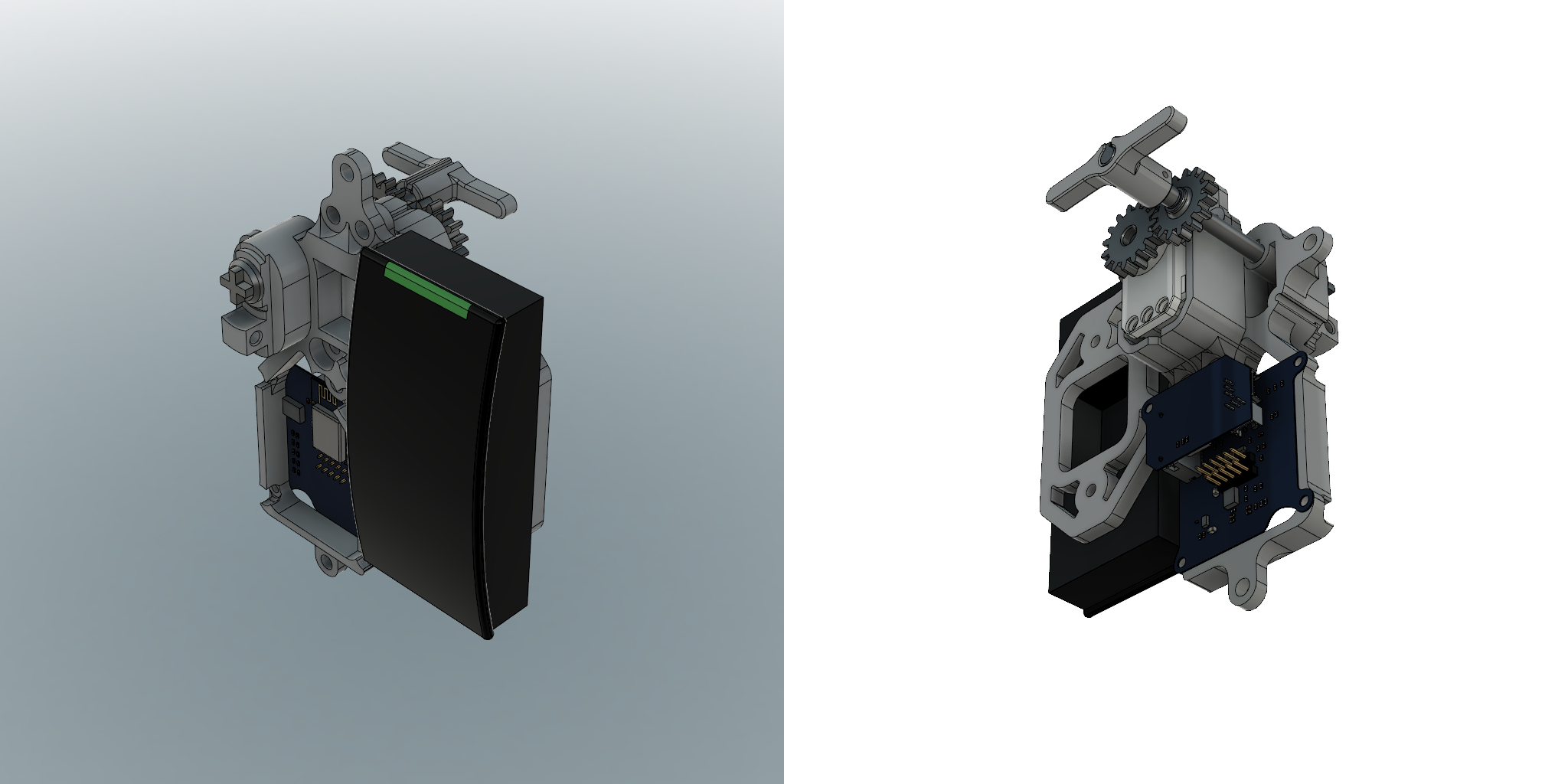
Casing
To protect the PCB and drivetrain we’ve designed a casing which is attached to the main platform. This casing also need to be 3D printed. However, this is difficult to do with an FDM printer since it either have to much overhang or non-flat surfaces, so this print will be outsourced. As mentioned, we aren’t fans of supports…
Renders
Here are few renders, just because we like rendering. 🙂
The Next Steps
What we’ll do next is to start printing the parts to check the fit and clearances. If they look ok we’ll print them at a higher quality at a professional 3D-printing service. We also need to write and test the firmware and the general electronics before assembling and mounting all the parts together.
Stay tuned for future updates on this project!