To take a picture on the exact moment you want to can be a hassle. But most cameras have the possibility to use an external shutter remote.
Connecting a regular button here does not help us, but by creating a simple computer system to take a picture at the perfect moment we are going to become very happy!
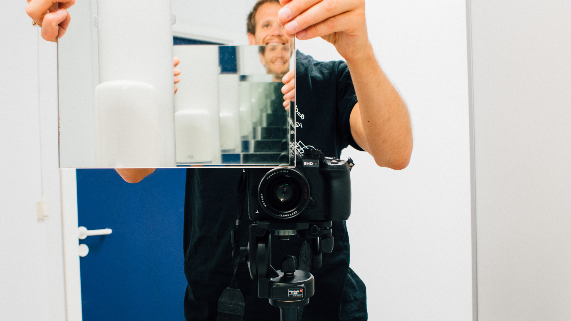
Our Camera
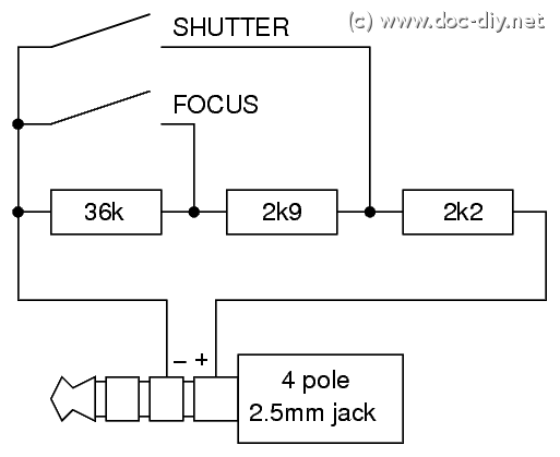
In this modification we used a Lumix GH5. It has a remote control input that can be used to focus and trigger the camera shutter. After some googling we found this on doc-diy.net:
Our Remote Triggering System
We only need to trigger the shutter. And to do that we need to place a resistor on approximate 2.2 k Ohms between the innermost to poles on the 2.2 mm jack. And when we don’t want to trigger the shutter the same poles needs to see (36 k Ohm + 2.9 k Ohm + 2.2 k Ohm) = 41.1 k Ohm. This last “idle” resistance is probably there so that the camera can sense that an external remote is connected. This had to be present when the camera started.
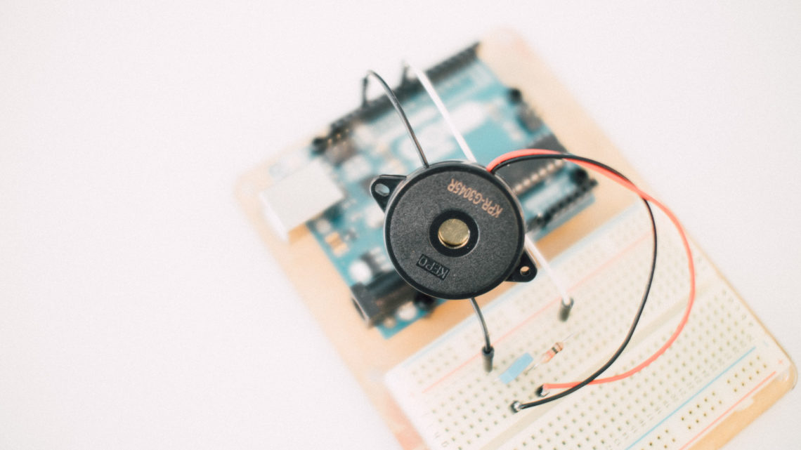
So we made a quick breadboard setup like this:
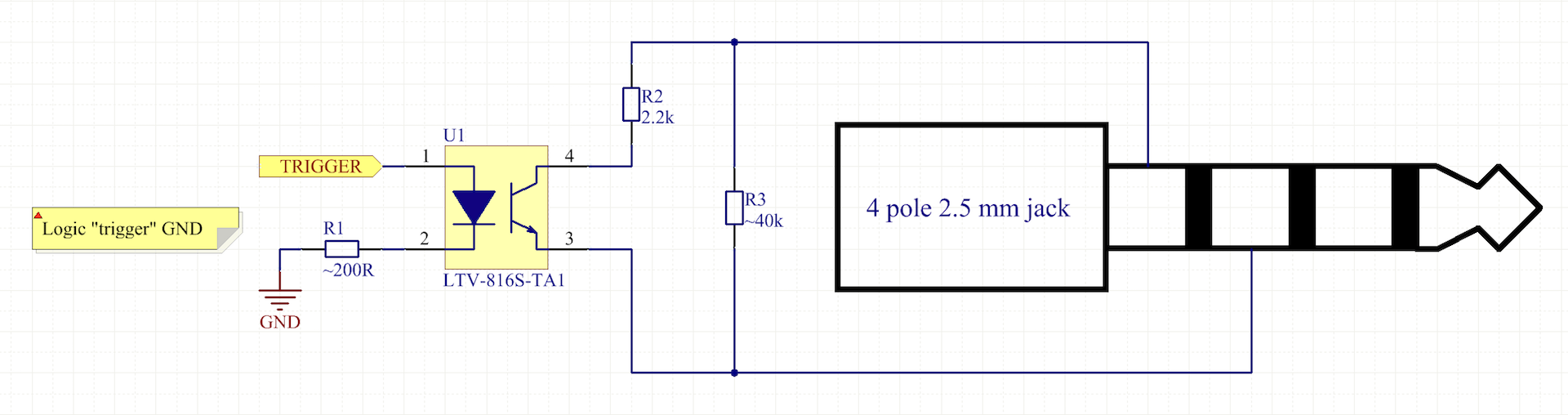
We used a 40 k Ohm resistor for the “idle” resistance, and it worked perfectly. The same applied to the 2.2 k Ohm resistor we placed in parallel when we wanted to trigger the shutter.
We chose to control the inserting of the 2.2 k Ohm resistor with an optocoupler. This could of course have been done with something like a relay (since the speed is low). But a opto was the closest component:P
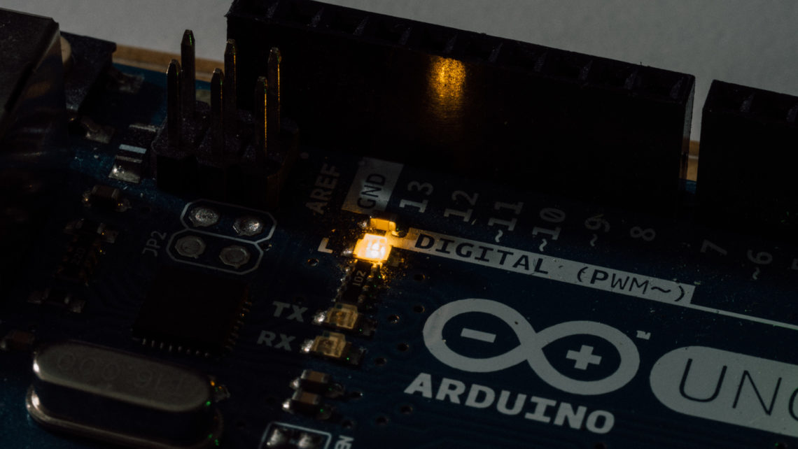
This “trigger circuit” was controlled by a regular output on an Arduino. And the Arduino did also have an LG-JG20MA sensor connected. This sensor was used to trigger the Arduino.
This was the firmware we used:
#define SENSOR_PIN 3
#define TRIGGER_PIN 2

void setup() {
  pinMode(TRIGGER_PIN, OUTPUT);
  digitalWrite(TRIGGER_PIN, LOW);

  pinMode(SENSOR_PIN, INPUT_PULLUP);

  Serial.begin(9600);
}

void camera_trigger(){
  digitalWrite(TRIGGER_PIN, HIGH);
  delay(100);
  digitalWrite(TRIGGER_PIN, LOW);
}

uint8_t read_sensor(){
  return digitalRead(SENSOR_PIN);
}

void loop() {
  if(!read_sensor()){
    delay(270); // Delay after triggered sensor
    camera_trigger();
    delay(2000); // Just a random "back off" delay
  }
}
Putting It All Together
Our quick demonstration setup was like this
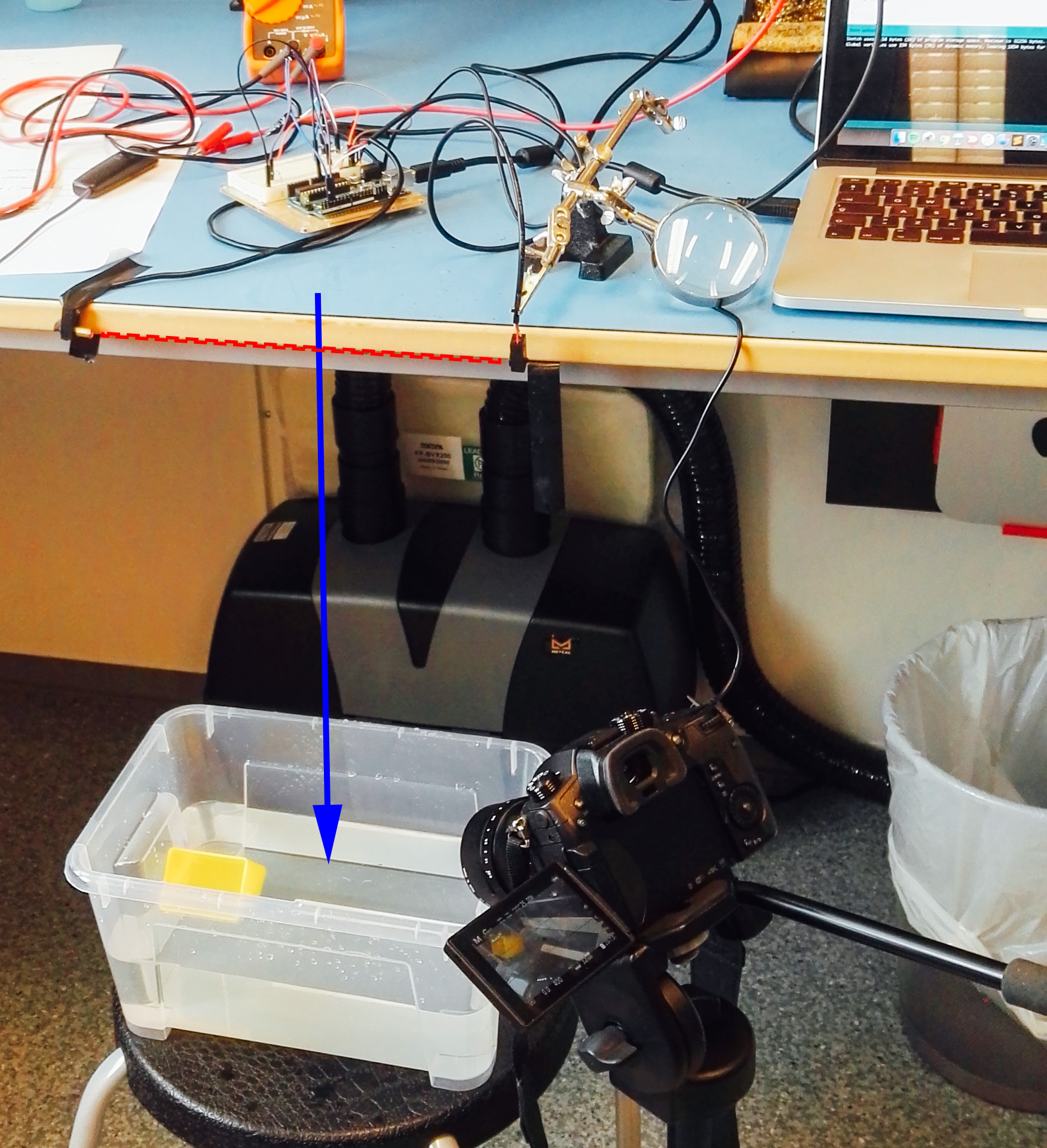
And our “algorithm” was like this:
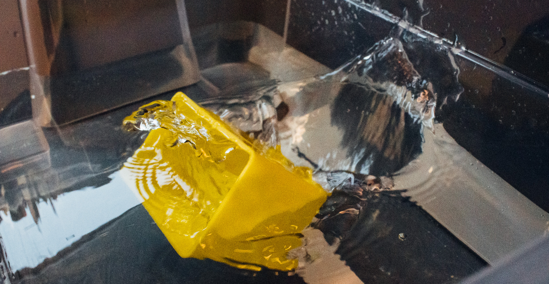
- We pushed the small yellow box down from the table.
- The box triggered the LG-JG20MA when it started falling towards the box filled with water
- The Arduino started counting down the delay on line 25. To determine this we did some trial and error
- After the delay was handled the Arduino triggered the shutter on the camera by using its output and the “trigger circuit”
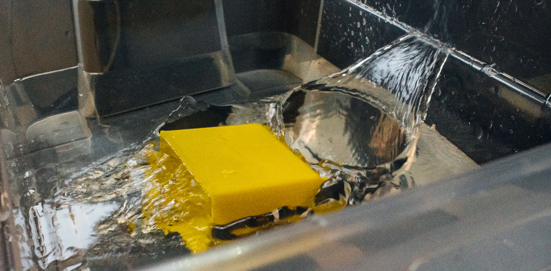
- The shutter was triggered at the perfect time
This was done in a dark cave without the use of much external light. The shutter time had to be very low, and to accomplish this we increased the ISO.
The rather ugly images are for system demonstration purposes only. The high ISO used destroyed them with noise.
It worked! Now onto some more “serious” image taking 🙂 And maybe with some other sensors?