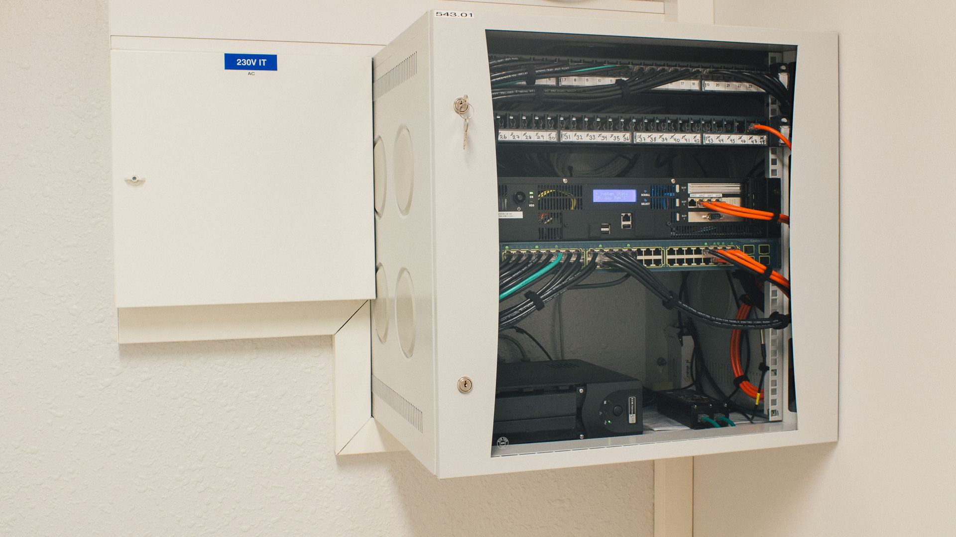
Here at Norwegian Creations we occasionally need to monitor the temperature of a system. Sometimes we have done this with our DMM with data logging capabilities. But it’s a bad idea to impound our DMM’s for long periods. Therefore we need a different solution for long time monitoring. Our monitoring applications could be anything from room temperatures, cooling systems, server racks or as in this picture, network equipment cabinets:
This blog post will show you how to build your very own temperature monitoring system in a step-by-step-fashion.
Introduction
To monitor the temperature in one of our netweork equipment cabinets we have made a system based on a cheap small Orange Pi Zero combined with the classic Maxim DS18B20 temperature sensor. The Orange Pi Zero is running Armbian, which is a Lightweight Debian (or Ubuntu) based Linux distribution.
With this combination of hardware we can interface the DS18B20 sensors through one GPIO pin and read out the temperature (1-WIRE / “One Wire” kernel support) . Then we can install the SNMP Daemon software (Net-SNMP), which is an SNMP agent that can answer SNMP requests from a central data logging server. This server could be anything from a self written script to more complex setups such as Nagios, Zabbix or LibreNMS to mention a few. In the server/networking world SNMP is the industry standard protocol for transferring monitoring parameters such as temperatures, etc.
What You Need
In order to build this, you need the following parts:
- Orange Pi Zero. Link. I think we bought it off AliExpress.
- microSD memory card. We have used a 16GB card we had laying around.
- Power Supply 5V micro USB. We had this laying around as well. Currently we use a 2A 5V PSU, but we think you should be fine with a 1A-1.5A as well (not confirmed).
- Maxim DS18B20 sensor(s). We use similar as these, they are in a useful casing pre-terminated with a 1M/2M lead. Several places have them or similar: Adafruit, Sparkfun, Ebay search.
- Regular 4K7 Ohm through hole resistor.
- One Terminal block or soldering iron.
If you want, we do not see any problem with implementing this on a Raspberry Pi instead of the Orange Pi Zero. The Raspberry Pi should have the same 1-WIRE kernel support and the rest of the software should be compatible. However, we haven’t tried this ourselves. Mainly due to that we like the small size of the Orange Pi Zero combined with wired Ethernet and what we had in stock when doing this.
Do It Yourself
From now on this will be a DIY tutorial so that you can replicate what we have done to make your own temperature monitoring probe. Currently this is our beta version, we have plans for improving this solution over time.

In this tutorial we assume that you have basic knowledge of how Armbian / Orange Pi / Raspberry Pi systems work. If you feel you don’t have that, do not panic! There exsits a lot of information online. The Armbian Documentation is a good place to start looking if you encounter problems. Even more beginner? This “Beginners Guide to the Orange Pi Zero” written by Luc Small” is a excellent start for the newcomers! And it fits perfectly for this DIY tutorial.
Step 1
We need to flash the Armbian image to the SD card. Grab the latest Armbian release and follow their guide for flashing. Etcher is a tool that have worked flawlessly for us on both Linux and Windows clients.
Put the freshly baked SD card into the Orange Pi Zero. Connect the network cable (from your router/switch) and the power cable. The Orange Pi Zero will now automatically power on and start booting, be patient and wait for the red LED to blink.
If you can’t get the red LED to blink it indicates that something is wrong. Try to read the beginners guide linked above or search online for solutions to your problem. From our experience this is often caused by either wrongly flashed SD card, bad SD card or bad Power Supply.
Step 2
Now we want to connect to the Orange Pi Zero through the network. We use a protocol called SSH. Open up your Terminal (or Putty is a great way if you are on Windows) type in the following:
ssh root@<IPADDRESS>
Where <IPADDRESS> is the IP address that your system have gotten from your router. This is typically 10.0.0.x or 192.168.0.x, where “x” is dependent on the DHCP server (“router”) in your network. To find this IP address you can log into your router and look for a “computer” named “orangepi” on your network. If you don’t have access to your router, scan the network for devices that are listening for connections on port 22 with a port scanning tool (search online for how to’s).
The first time root password of Armbian is “1234“. Log in with this.
Step 3
With the new system we have some basic configuration tasks to do.
Right after the first root login you will be prompted to change / set new secret password. Do that!
Note: you must first type in the current password (“1234”) before setting the new password.
Then follow the provided setup guide and add new user. We have kept it pretty basic and called our user “orangepi” with our own secret password.
When the setup guide is finished you must reboot the system. Do this with the command:
orangepi@orangepizero:~$ sudo reboot
Grab a coffee and be patient on the next boot, the system will resize the file system for your SD card. This could easily take 5-10 minutes.
After the system have booted, log in through SSH.
Now we should update the software on your system, do that by typing in:
orangepi@orangepizero:~$ sudo apt-get update &amp;&amp; sudo apt-get upgrade
Step 4
Now we need to enable the 1-WIRE / “One Wire” kernel support. This will let us be able to read out the temperature from our sensors.
Edit the following file with your preferred text editing tool, if you are newcomer, nano should be a good start:
orangepi@orangepizero:~$ sudo nano /etc/modules-load.d/modules.conf
Comment out the “w1-therm”, “w1-gpio” and “w1-sunxi” lines. This is how our file look like after the edit:
w1-sunxi
w1-gpio
w1-therm
#sunxi-cir
#xradio_wlan
g_serial
#xradio_wlan
Note: we have also disabled the XR819 wireless chip (it’s useless and have really bad driver support) by adding “#” in front of every “xradio_wlan” line.
Now we need to correct a bug that is present in the current kernel versions:
orangepi@orangepizero:~$ sudo nano /etc/default/cpufrequtils
Add the following lines:
ENABLE=true
MIN_SPEED=480000
MAX_SPEED=1200000
GOVERNOR=interactive
Power off the system with:
orangepi@orangepizero:~$ sudo poweroff
Step 5
Now we should connect the physical temperature sensors to the Orange Pi Zero. Ensure that you have removed the power!
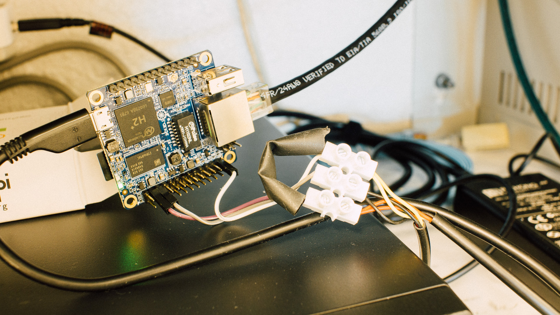
Connect the three wires from the temperature sensor(s) like this:
Positive (red): 5V –> Physical pin 2 or pin 4
Data (yellow): GPIO10/PA10 –> Physical pin 26
Ground (black): GND –> Physical pin 6 or pin 25
To know where those pins are on the Orange Pi Zero, take a look here.
In addition you must add a 4.7KΩ (4700Ω) resistor between the Data and Positive line (red and yellow). We have done this in the terminal block in the picture above (resistor inside the black heat shrink tube).
If you have multiple temperature sensors all of them should be connected in parallel, all the red wires together, yellow wires together and black wires together.
Connect the power back to the Orange Pi Zero, wait for the device to come online and SSH back into it.
Jump over to a new blog post about a custom made daughter card that makes connections better and adds some nice additional features here!
Step 6
Now we should test if we can read out the temperature from our newly connected sensors.
Check if the system has found any 1-WIRE devices:
orangepi@orangepizero:~$ cat /sys/devices/w1_bus_master1/w1_master_slave_count
2
The output should match your number of connected temperature sensors. Do not proceed if you get 0, then it can’t find any sensors, go back and check the kernel configuration in Step 4 and double check the connections made in Step 5.
Now we can test if we can read out the temperature from one sensor:
orangepi@orangepizero:~$ cat /sys/bus/w1/devices/28-0000XXXXXXXX/w1_slave
Where XXXXXXXX is the unique ID of your sensor(s). You can find those by using “Tab” key or listing files in the same folder (“ls -l /sys/bus/w1/devices/”).
The output should be something similar to this:
c7 01 4b 46 7f ff 09 10 01 : crc=01 YES
c7 01 4b 46 7f ff 09 10 01 t=28437
From this we can see that the CRC is OK with “YES“. If you get “NO” you should check your connections and that you have the correct resistor. We can also see that the measured temperature is 28.437°C 🙂
If you have multiple sensors connected, check that all of them works and have “crc = 01 YES” in the output.
Step 7
Now we need to install the necessary SNMP dependencies and add loading of a module called “Extend”.
orangepi@orangepizero:~$ sudo apt-get update &amp;&amp; sudo apt-get install snmpd snmp-mibs-downloader
Due to a unknown reason, the extend module is not loaded by default. Therefore we need to add it manually:
orangepi@orangepizero:~$ sudo nano /etc/default/snmpd
Change the following line:
# snmpd options (use syslog, close stdin/out/err).
SNMPDOPTS='-Lsd -Lf /dev/null -u snmp -g snmp -I -smux,mteTrigger,mteTriggerConf -p /run/snmpd.pid'
To include “extend” on the end of “-I”:
Our version does look like this after the edit:
# snmpd options (use syslog, close stdin/out/err).
SNMPDOPTS='-Lsd -Lf /dev/null -u snmp -g snmp -I extend -smux,mteTrigger,mteTriggerConf -p /run/snmpd.pid'
Step 8
Now we need to download and install the necessary scripts (provided by us):
orangepi@orangepizero:~$ cd /opt/
orangepi@orangepizero:/opt$ sudo git clone -b 1-0-release https://github.com/NorwegianCreations/snmpmoni.git
orangepi@orangepizero:/opt$ cd snmpmoni/
orangepi@orangepizero:/opt/snmpmoni$ sudo cp config/snmpd.conf.example /etc/snmp/snmpd.conf
Thereafter, you must edit and configure your snmpd example config provided by us:
orangepi@orangepizero:~$ sudo nano /etc/snmp/snmpd.conf
As a minimum you must configure the community and allowed IP address under the access control section.
For testing here at Norwegian Creations we have just used the following access control configuration:
rocommunity public 10.0.0.33
This allows the computer with IP address 10.0.0.33 to query all available SNMP parameters (read-only).
You should also go through the rest of the configuration file.
When finished, save the snmpd.conf file and exit the text editor.
Step 9
Hang in there, the final thing we need to do is to configure a mapping between temperature sensor ID and SNMP object (“OID”). This is what “connects” each temperature sensor to the various SNMP OIDs.
Start by listing all of your current temperature sensor(s) unique ID:
orangepi@orangepizero:~$ ls -l /sys/bus/w1/devices/28-*
Our output on the test system is:
orangepi@orangepizero:~$ ls -l /sys/bus/w1/devices/28-* lrwxrwxrwx 1 root root 0 Jan 22 16:21 /sys/bus/w1/devices/28-0000042af565 -&gt; ../../../devices/w1_bus_master1/28-0000042af565 lrwxrwxrwx 1 root root 0 Jan 22 16:21 /sys/bus/w1/devices/28-000004a8a98e -&gt; ../../../devices/w1_bus_master1/28-000004a8a98e
Where the ID is the numbers starting with “28-000004” above. Take note of all of your ID’s.
For us this is “28-0000042af565” and “28-000004a8a98e”.
In the current source code, two example mappings is already present. To edit and create new mappings, do the following:
orangepi@orangepizero:~$ cd /opt/snmpmoni/mapping/
orangepi@orangepizero:/opt/snmpmoni/mapping$ sudo nano iso.3.6.1.4.1.50083.100.4.1.1.1.7.1
Now replace the content in the file with the complete temperature sensor ID of your first sensor. If you have multiple sensors, edit the next file and insert the next temperature sensor ID. If you have more than two sensors you need to add the next file after that.
The current beta version allow up to eight temperature sensors with the following OID’s:
iso.3.6.1.4.1.50083.100.4.1.1.1.7.1
iso.3.6.1.4.1.50083.100.4.1.1.1.7.2
iso.3.6.1.4.1.50083.100.4.1.1.1.7.3
iso.3.6.1.4.1.50083.100.4.1.1.1.7.4
iso.3.6.1.4.1.50083.100.4.1.1.1.7.5
iso.3.6.1.4.1.50083.100.4.1.1.1.7.6
iso.3.6.1.4.1.50083.100.4.1.1.1.7.7
iso.3.6.1.4.1.50083.100.4.1.1.1.7.8
Note: all of those OIDs numbers are under Norwegian Creations control. We do have our own SNMP OID in the “private enterprise” space assigned by Internet Assigned Numbers Authority (IANA).
So by using those OID’s you will not get any conflicting OID’s on your system. And please respect the IANA registry and do not abuse our OID numbers for other purposes than what we provide.
To summarize the mapping procedure:
- Create a file in the “/opt/snmpmoni/mapping/ folder.
- This file should be named in accordance to what OID you are mapping (iso.3.6.1.4.1.50083.100.4.1.1.1.7.[1-8]).
- iso.3.6.1.4.1.50083.100.4.1.1.1.7.1 for temperature sensor 1
- iso.3.6.1.4.1.50083.100.4.1.1.1.7.2 for temperature sensor 2
- iso.3.6.1.4.1.50083.100.4.1.1.1.7.3 …. and so on
- Inside the file, only add one line of text with the unique ID of your temperature sensor. Such as:
28-0000042af565
Step 10
Now it’s time to start / restart the SNMP daemon:
orangepi@orangepizero:~$ sudo service snmpd restart &amp;&amp; sudo service snmpd status
With the SNMP Daemon running we could test from a monitoring client. Head over to your monitoring server or a regular client computer that is allowed access to query for SNMP values (remember the access control section from Step 8? ).
From this server we can now issue the following command (you must have the SNMP client installed), replace <IP ADDRESS> with your IP address for the Orange Pi Zero:
may@may:~$ snmpwalk -v 1 -c public &lt;IP ADDRESS&gt; iso.3.6.1.4.1.50083.100.4.1.1.1.7.1 iso.3.6.1.4.1.50083.100.4.1.1.1.7.1.1.0 = INTEGER: 1 iso.3.6.1.4.1.50083.100.4.1.1.1.7.1.2.1.2.5.116.104.101.114.109 = STRING: "/bin/bash" iso.3.6.1.4.1.50083.100.4.1.1.1.7.1.2.1.3.5.116.104.101.114.109 = STRING: "/opt/snmpmoni/bin/ds18b20.sh -g iso.3.6.1.4.1.50083.100.4.1.1.1.7.1" iso.3.6.1.4.1.50083.100.4.1.1.1.7.1.2.1.4.5.116.104.101.114.109 = "" iso.3.6.1.4.1.50083.100.4.1.1.1.7.1.2.1.5.5.116.104.101.114.109 = INTEGER: 5 iso.3.6.1.4.1.50083.100.4.1.1.1.7.1.2.1.6.5.116.104.101.114.109 = INTEGER: 1 iso.3.6.1.4.1.50083.100.4.1.1.1.7.1.2.1.7.5.116.104.101.114.109 = INTEGER: 1 iso.3.6.1.4.1.50083.100.4.1.1.1.7.1.2.1.20.5.116.104.101.114.109 = INTEGER: 4 iso.3.6.1.4.1.50083.100.4.1.1.1.7.1.2.1.21.5.116.104.101.114.109 = INTEGER: 1 iso.3.6.1.4.1.50083.100.4.1.1.1.7.1.3.1.1.5.116.104.101.114.109 = STRING: "28.437" iso.3.6.1.4.1.50083.100.4.1.1.1.7.1.3.1.2.5.116.104.101.114.109 = STRING: "28.437" iso.3.6.1.4.1.50083.100.4.1.1.1.7.1.3.1.3.5.116.104.101.114.109 = INTEGER: 1 iso.3.6.1.4.1.50083.100.4.1.1.1.7.1.3.1.4.5.116.104.101.114.109 = INTEGER: 0 iso.3.6.1.4.1.50083.100.4.1.1.1.7.1.4.1.2.5.116.104.101.114.109.1 = STRING: "28.437"
As you can see from the output we have successfully received our temperature:
iso.3.6.1.4.1.50083.100.4.1.1.1.7.1.3.1.1.5.116.104.101.114.109 = STRING: "28.437"
Note: This assumes that you are using the basic unencrypted v1/v2 version of SNMP. This tutorial have used that for testing purpose. If you have switched to SNMP v3 then you just need to modify the snmpwalk command to include the credentials of your system.
Step 11
Strictly this step is not a part of the tutorial, but a small explanation does fit in here.
After Step 10, the Orange Pi Zero successfully answers SNMP requests with the temperatures. However to be able utilize this in a sensible application we must connect this with a monitoring server.
You probably already have one deployed in your network infrastructure or we would encourage to set this up. If you don’t have a monitoring server you could also implement some lightweight scripts to log the temperature values (hint: you can utilize the Linux SNMP client, as partly shown in Step 10 above to gather the temperature).
As mentioned in the Introduction, this system works with everything that “speaks” SNMP. Existing monitoring systems as Nagios, Zabbix and LibreNMS should all work.
To show how the resulting solution could be, we have implemented our test system with a Zabbix Monitoring server.
Our resulting graphs does look like this:
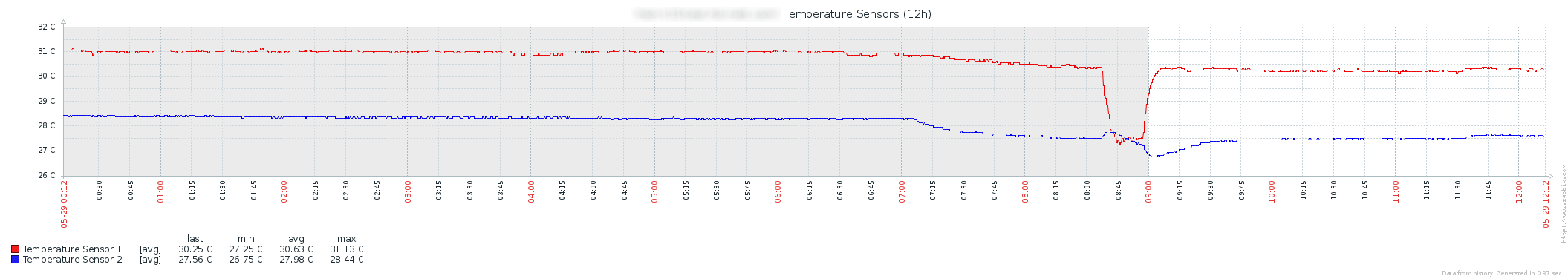
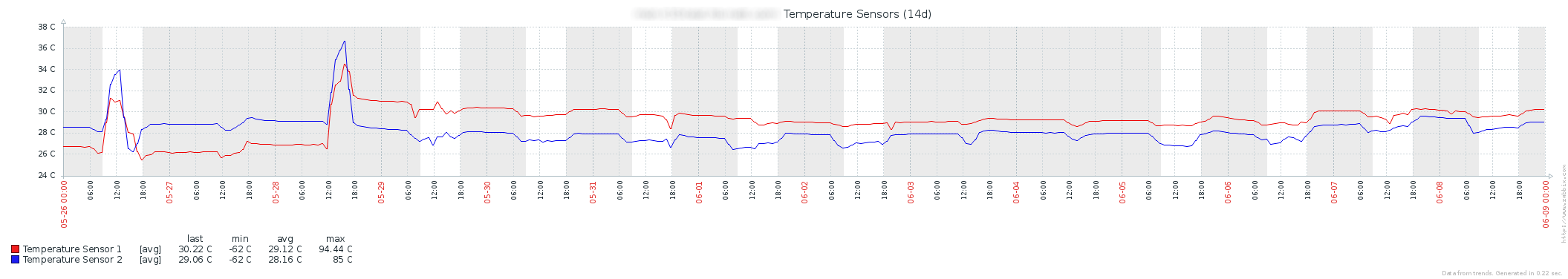
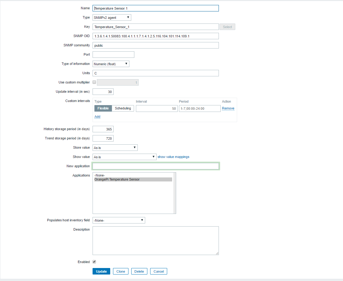
Our Zabbix configuration is done by adding a new Zabbix Template, with Items such as this:
That’s it, you should now have a working system!

Having trouble?
If you have had trouble while doing the tutorial, please search online after solutions for your specific problem. This tutorial have many possible pitfalls and we can’t cover them all.
If you still believe that we have an error in our tutorial or after a thorough search online can’t find a solution to your problem, don’t hesitate giving us a comment below.
We do also appreciate any feedback, good and bad!
Resources used while doing this
When we made this tutorial we have used several resources online, some for inspiration and some for actual solution(s). Thanks to everybody in this list:
- Raspberry Pi Forum – Temp collector with SNMP
- tech@graze – environment modelling with a raspberry pi
- Iana – Structure of Management Information (SMI) Numbers
- Alvestrand – OID search engine
The road ahead
As earlier stated this is our Beta Version. Currently we are aware of the following issues / improvements that could be made:
- Design a 3D printed casing for the Orange Pi Zero.
- Introduce a better cabling system to allow easy modular attachment of sensors.
- Do performance testing with multiple temperature sensors.
- Make an installation script to reduce the manual work needed to use this tutorial.
- Add verification of the CRC value when querying the SNMP OID (to avoid false values).
- Add a configurable data buffer between the SNMP Daemon and temperature sensor system.
- Make a configuration and management script with automatic sensor <-> OID mapping.
- Long time goal (if enough resources): Make a complete system image/iso for the complete unit (“plug and play” style) with a minimal Linux containing only the necessities.
We will probably over time iterate on this and solve many of those issues / improvements.
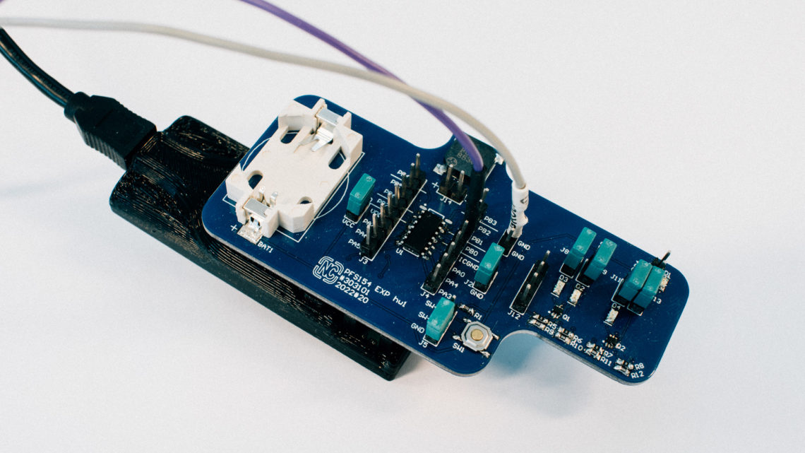
Update 19.09.2019:
Jump over to a new blog post about a custom made daughter card that makes connections better and adds some nice additional features here!