 For a while now we’ve had a drawing machine in development with the following main features:
- It uses an airbrush to draw.
- The drawing area is something vertical such as a wall or a canvas. The size of this drawing area can be arbitrary (within certain limits).
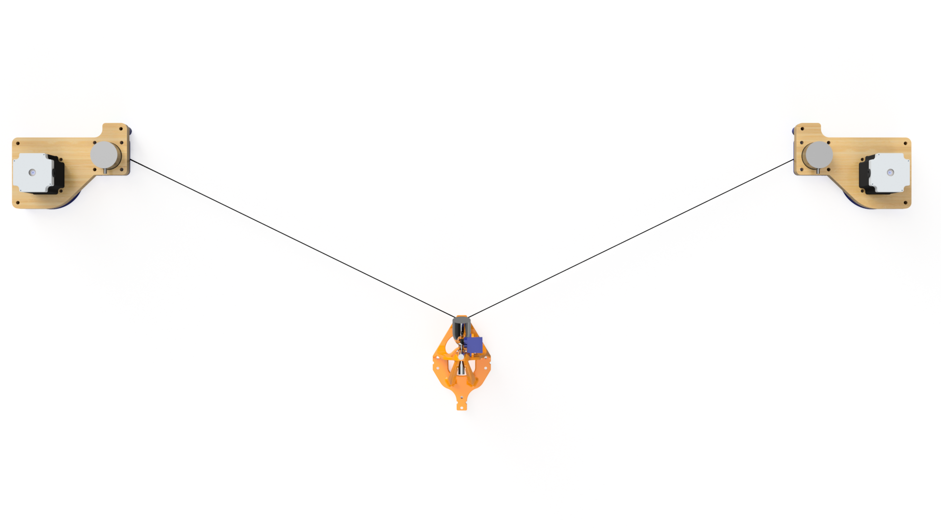
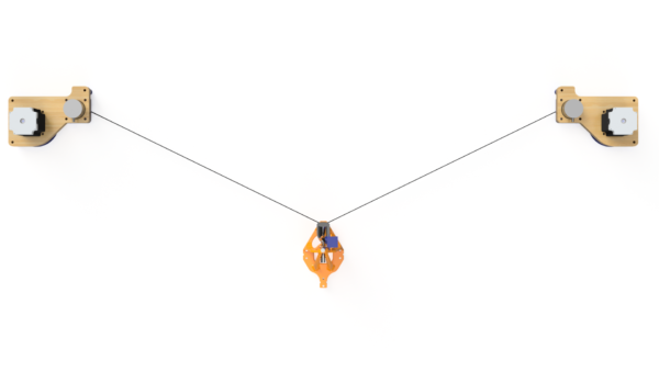
- It consists of three main parts
- A hanging “gondola” (as in gondola lifts) which travels around the canvas, drawing the picture.
- Two corner modules mounted in each of the upper corners of the drawing area.
This project is something we work with when we have some spare time and thus it is still in development. This post will show you what we have done so far as well as plans and ideas for further development.
Structurally it reminds a bit of this machine with regards to the two fixed corners and the hanging gondola.
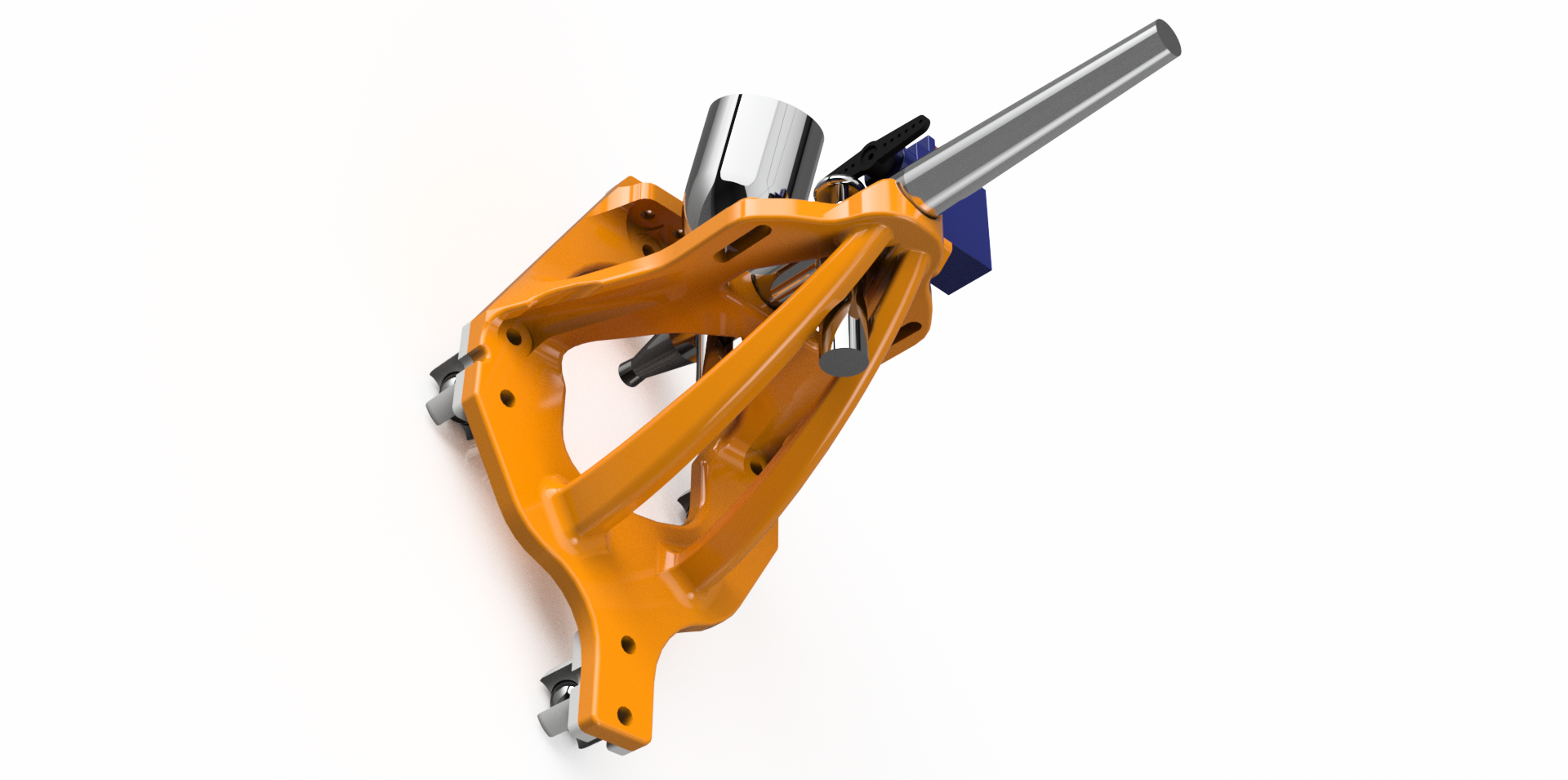
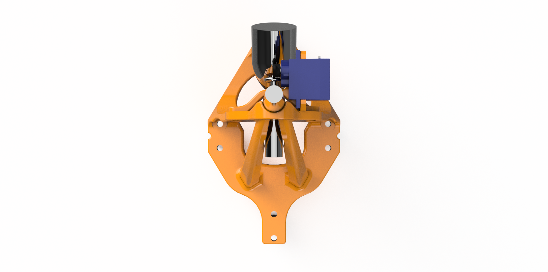
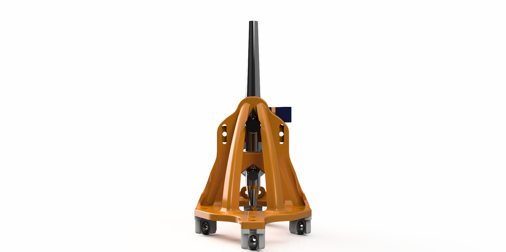
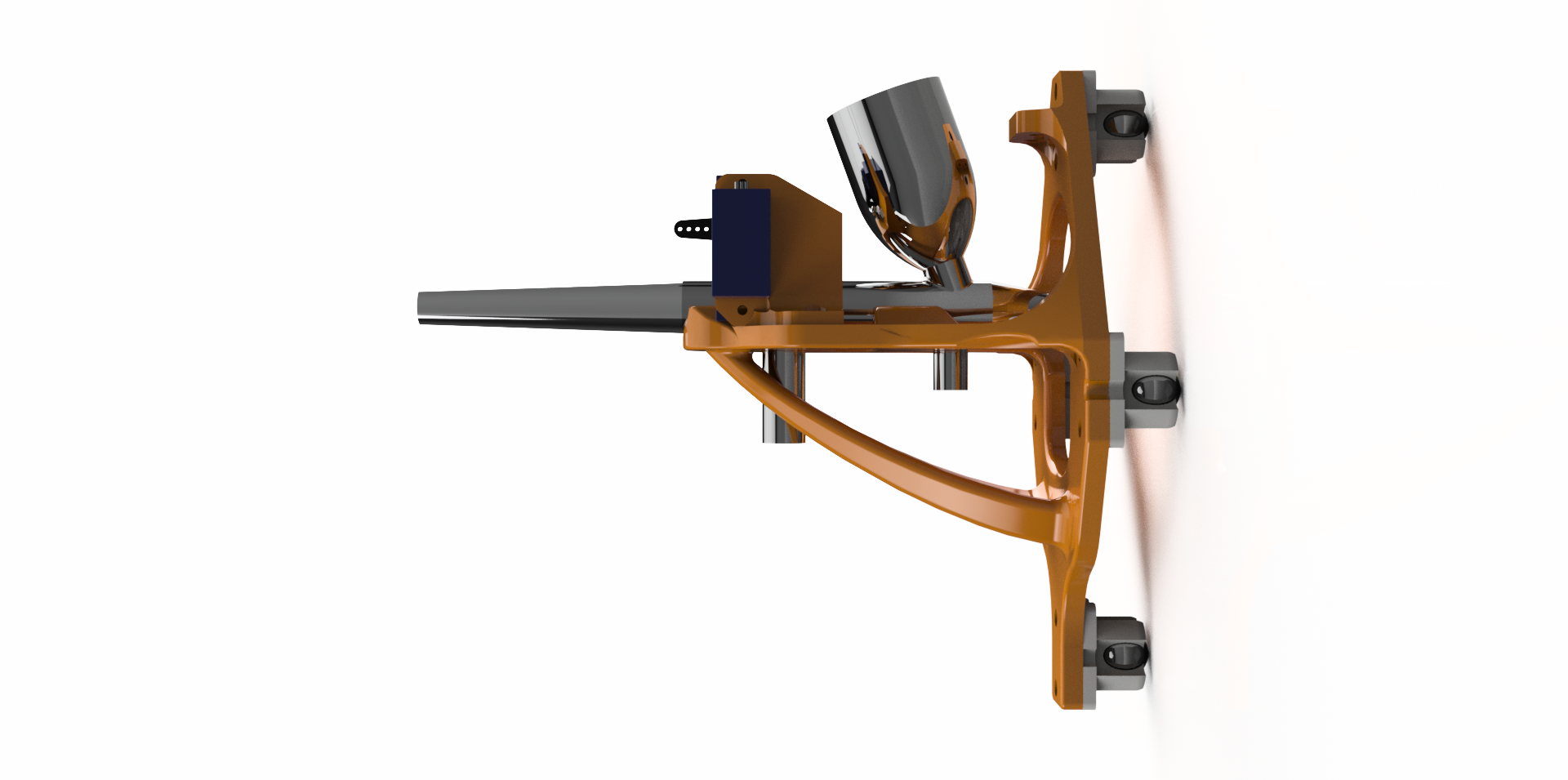
The Gondola
The part we’ve chosen to name the gondola is the only translationally moving module of the machine. It travels around the canvas and draws the image.
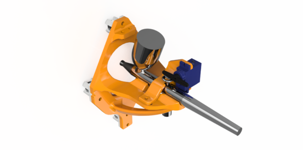

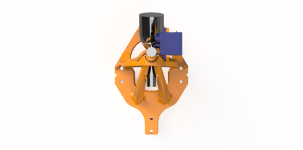
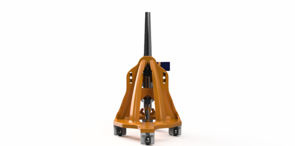
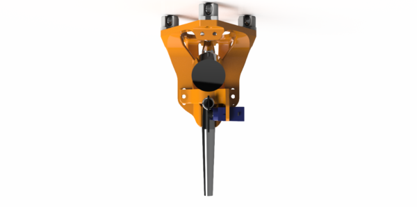
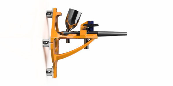
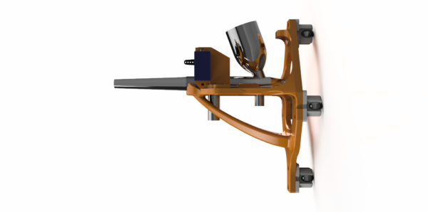
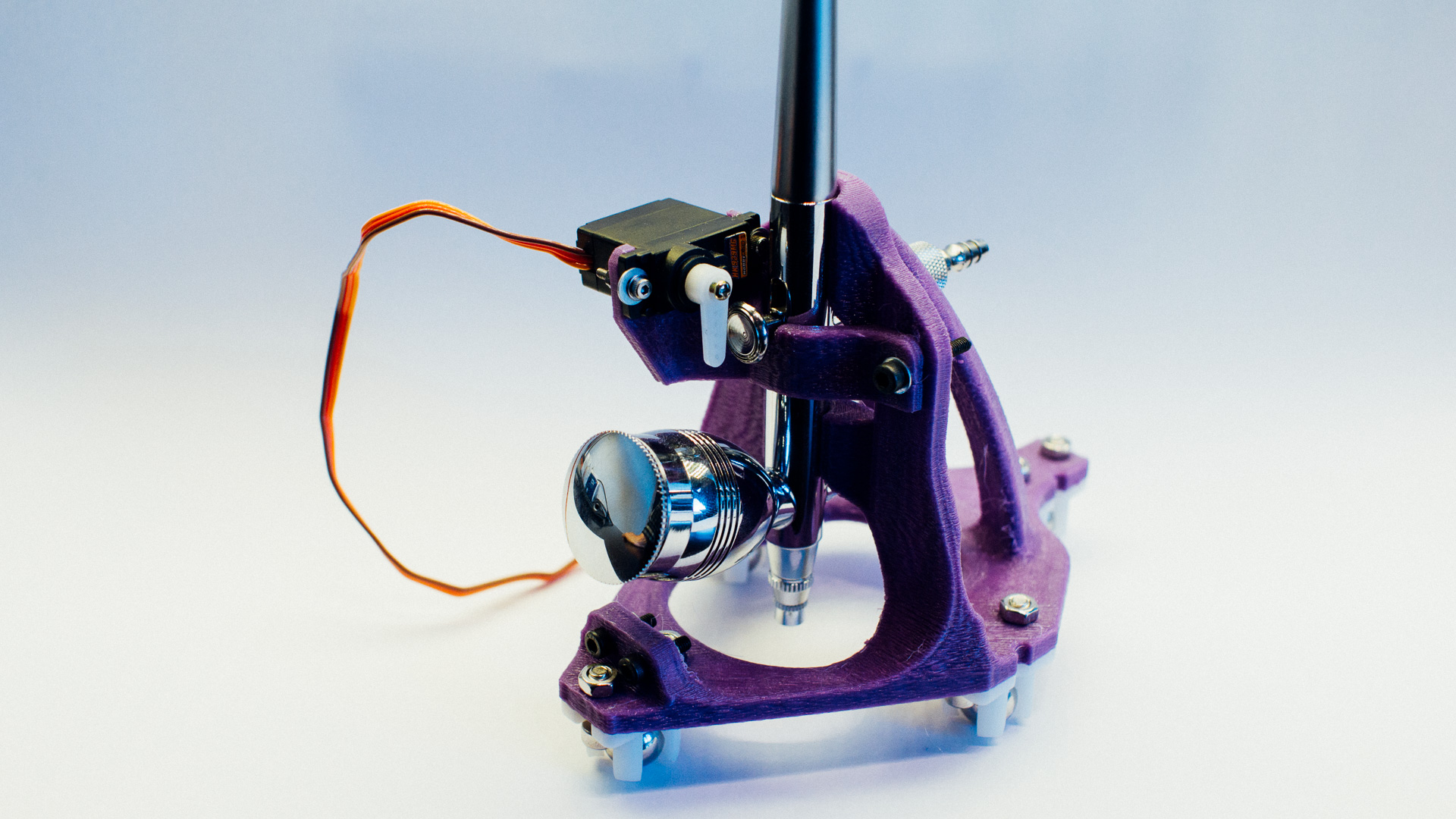
The Spray Gun and Actuation
We got hold of an airbrush spray gun from a local hardware store (Biltema) and modelled the gondola after that. The spray gun is actuated by a standard RC mini servo by pressing down the trigger with a servo horn.
The Body
The body consists of two parts. A main body and a “slider“.
The main body holds everything together. It cradles the spray gun and has fastening points for the belts that go to the corners. It is also the base for the wheels we use. These wheels are omnidirectional and are basically just steel balls inside plastic brackets.
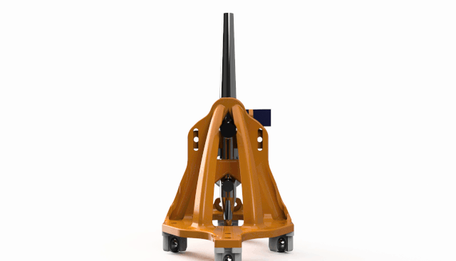
The slider can be manually adjusted to set the nozzle opening of the spray gun. On this spray gun the nozzle opening is adjusted by moving the trigger back and forth along the length axis of the gun (it is spring loaded towards the front). The slider holds the trigger in place where we want it along this axis so that we get a steady nozzle opening. The servo is fastened to the slider, so no relative movement is made between the servo and the trigger when adjusting the nozzle.
The Belts
The structural connection between the gondola and the corners are two GT2 belts. On each side, one end of the belt is fastened to the gondola while the other end is fastened to its respective corner.
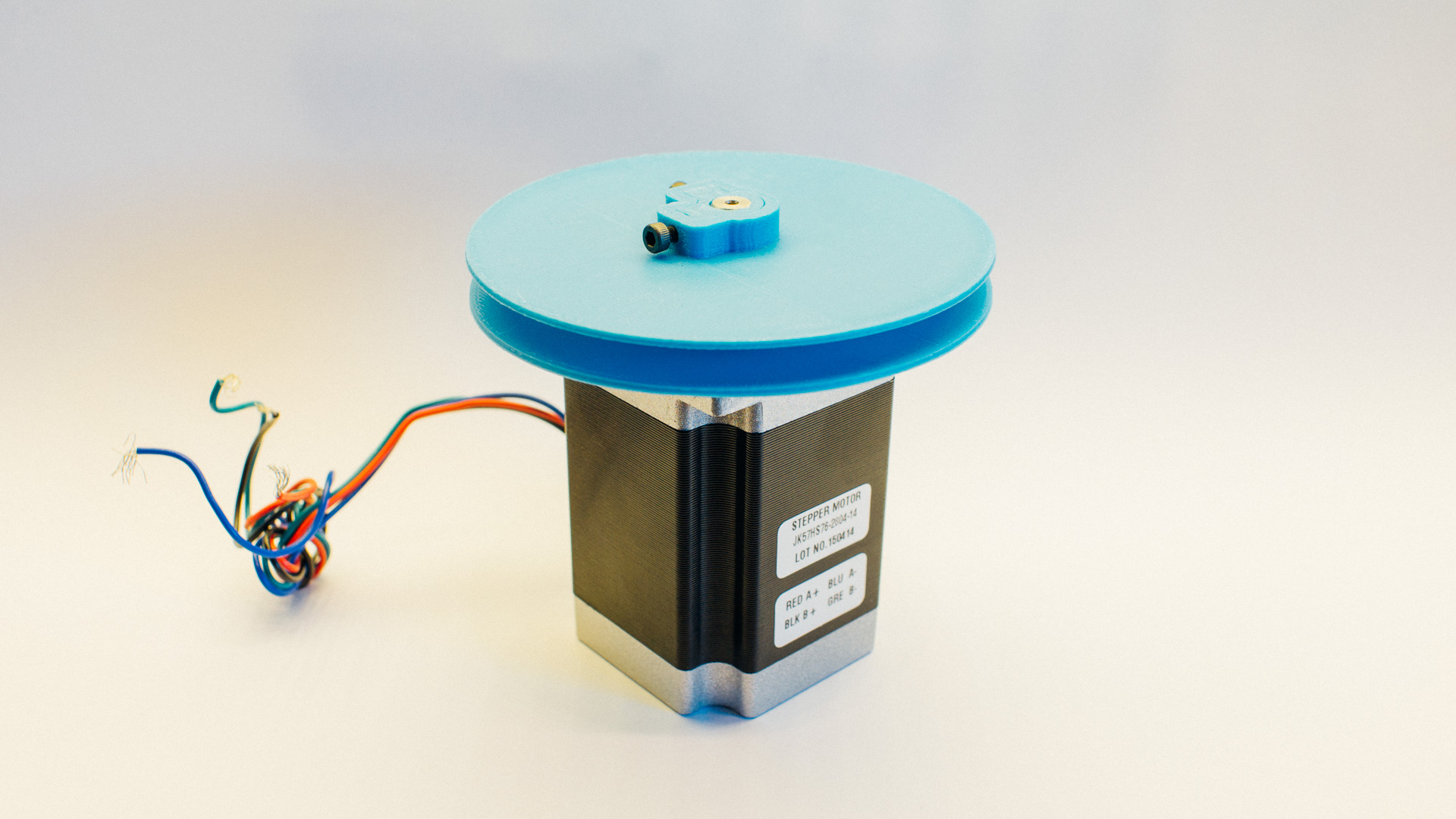
The Corners
The other main parts of the machine are the corners. These modules are fixed in top left and top right corner of the drawing area.
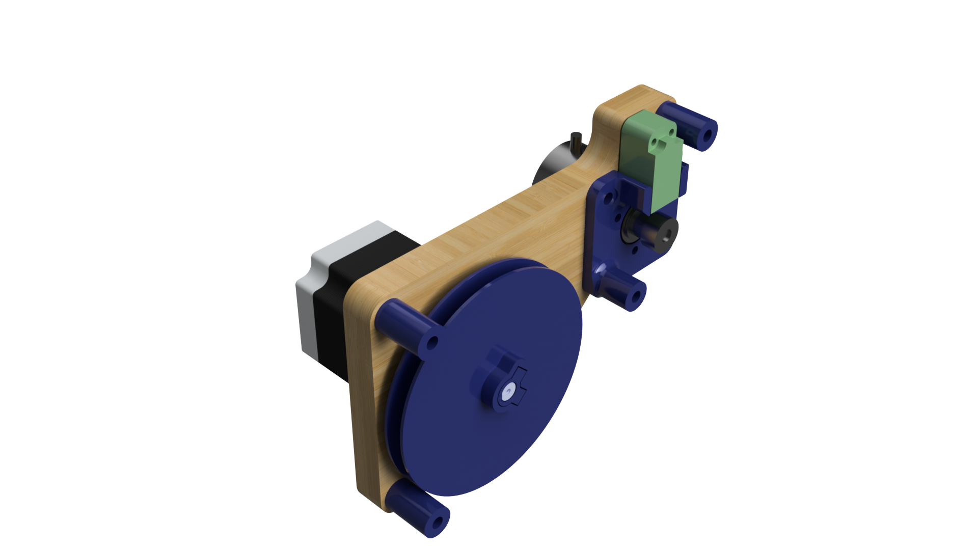
Each corner consists of:
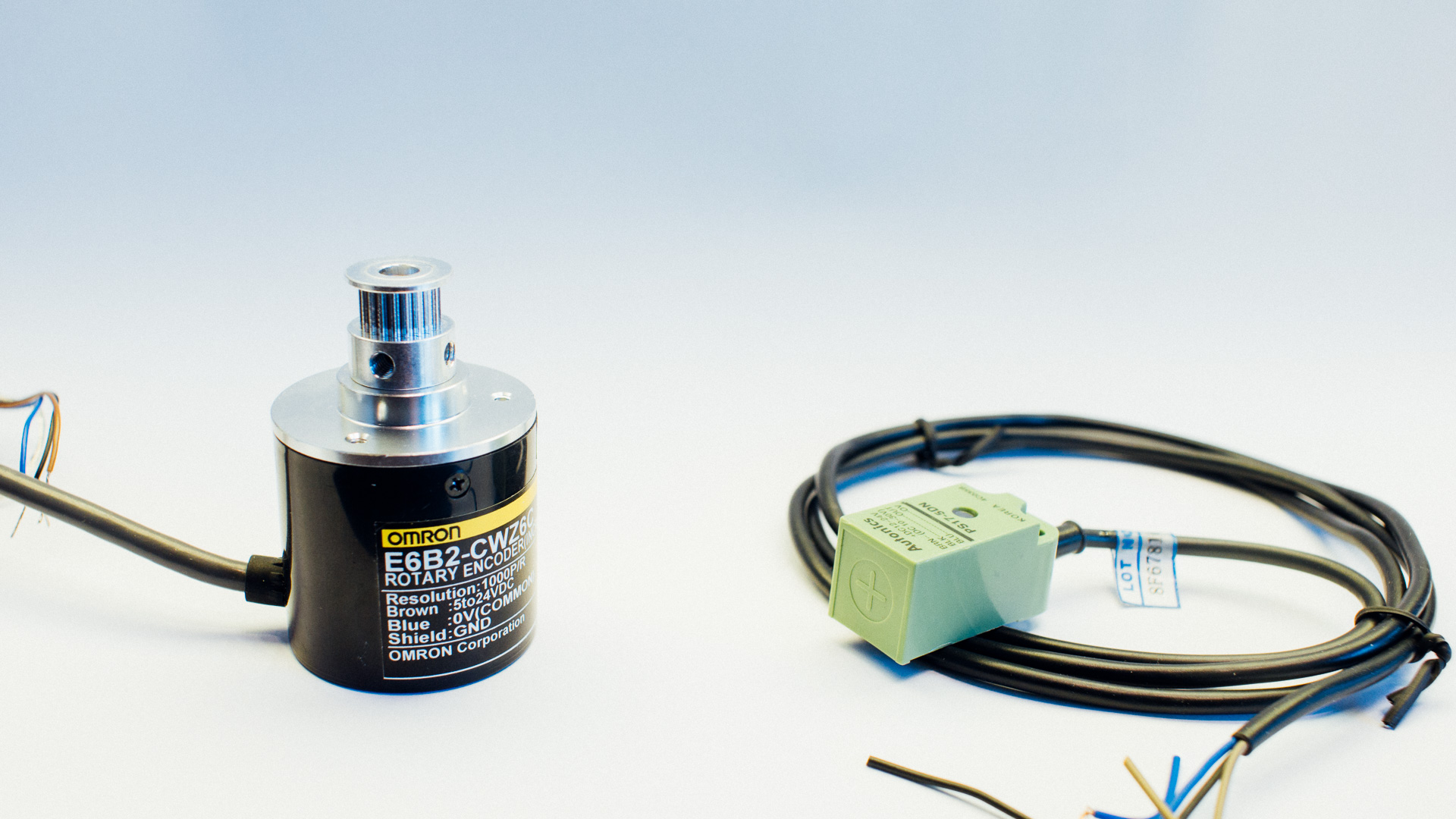
- A NEMA 23 stepper motor to actuate the movement
- An encoder with a pulley to accurately sense the movement
- A hall effect sensor to be used as an “end-stop switch” for homing purposes
- Various 3D printed components:
- A 2-piece spool to wind the belt around
- A bracket for the for the encoder and hall effect sensor
- Spacers between the wall and the corner body
- A CNC milled plywood piece which is regarded as the main corner body.
The belt is fastened to the center of the spool and wound layer by layer when the gondola is reeled in. The belt goes from the spool, via the encoder-pulley and out to the gondola. A piece of metal is glued on the flat side of the belt to define the zero-position of the gondola in one end. This piece of metal is sensed by the hall effect sensor during homing.
The spool has the same type of M3 inserts as we used in this casing.
Why the Need for an Encoder?
Ideally we would know exactly how much belt that’s reeled out at any given time by using only with the stepper motor and the hall effect sensor. However, since the radius of the belt spool varies as much as it does we need something else than the motor to monitor the belt movement. What we end up here is a feedback loop as discussed in this post.
We could of course calculate how much the radius of the spool varies with position, but we figured that just using an encoder would be both simpler and more accurate.
The Electronics and the Control
We have not yet specified these parts of the machine yet. However, we still have specific plans on what we want to do.
A central electronics module will be placed somewhere where the main embedded computer, motor drivers and power supply are put. We also need a compressor for the airbrush.
The machine will be fed G-code from a vectorized image. The computer will translate this G-code to gondola movement and airbrush control. We need to implement a more complex algorithm than we used in this machine to be able to draw true vectors.
What We’ve Done
So far, in addition to all the design, we’ve printed and assembled the complete gondola as well as tested the servo. We have also printed and mounted the spool. Motors, encoders, sensors, belts, pulleys and motor drivers are also been obtained.
The Road Ahead
The next steps will be to print and mill the rest of the corners. When everything is ready we need a rig to test the machine, set up the electronics and develop the control algorithm. The long-term goal is to be able to use this machine both in a rig with a canvas as well as mount it directly on a wall.
A Few Closing Words
The most important features of this machine is the dynamic drawing area and the airbrush drawing technique, and these features are what make it unique. The non-cartesian nature of the machine brings interesting challenges regarding the control algorithm. It will also be interesting to see how well the airbrush technique will work. A couple of concerns are that the gondola wheels might smudge out the paint on the canvas or that the gondola might lift off relatively to the canvas due to spray gun recoil. If any of this will become a problem that needs to be resolved remains to be seen.
This machine will probably not be ready in the very near future, but we’ll be sure to write another blogpost when more work has been made and we’re closer to a complete working drawing machine.


