Autodesk Fusion 360 has now an easy-to-use simulation module which can be used to simulate static stress, modal frequencies, heat and thermal stress. Many are not aware that Fusion 360, a software which actually is free for students, makers and small companies, has these features.
In this post we will take a look at how to do basic static stress simulations and talk a bit about why it might be useful.
Why do Static Stress Simulation?
When designing mechanical objects you often want them to be just adequately sturdy. Make the objects too whimpy and they will break. Make the objects too sturdy and they will be larger, heavier and/or more expensive than they need to be.
By simulating static stress you can strip down unnecessary parts and reinforce weak-points before sending your part to production, making your part strong where you need it to be and at the same time smaller, lighter and cheaper.
Having this type of simulation available within your CAD software makes it incredibly easy to go back and forth between tweaking your model and simulating.
Simulating Static Stress in Fusion 360
The first thing we need is a model.
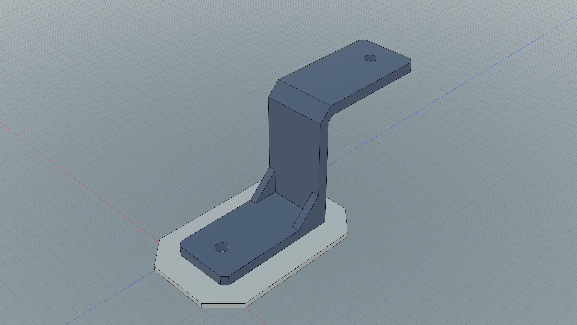
When you have a model to simulate, follow the steps below:
Step 1: Preperations
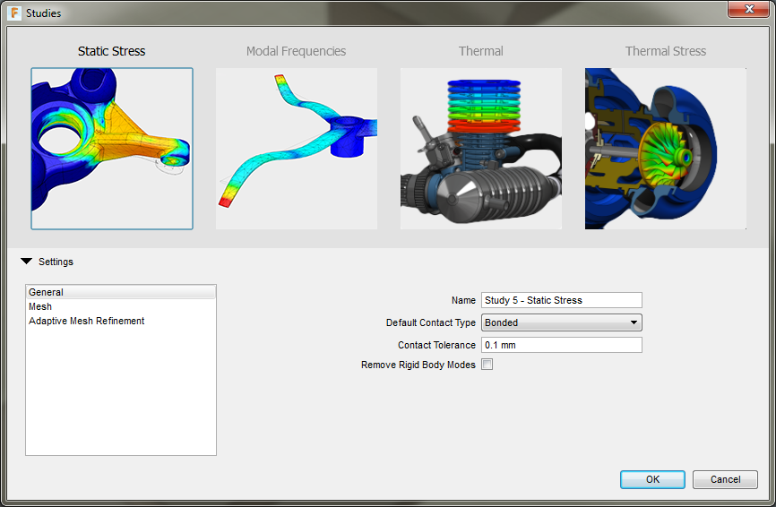
Enter the simulation module by clicking on the thingy in the top left on the toolbar. In the window that pops up after pressing Simulation select Static Stress.
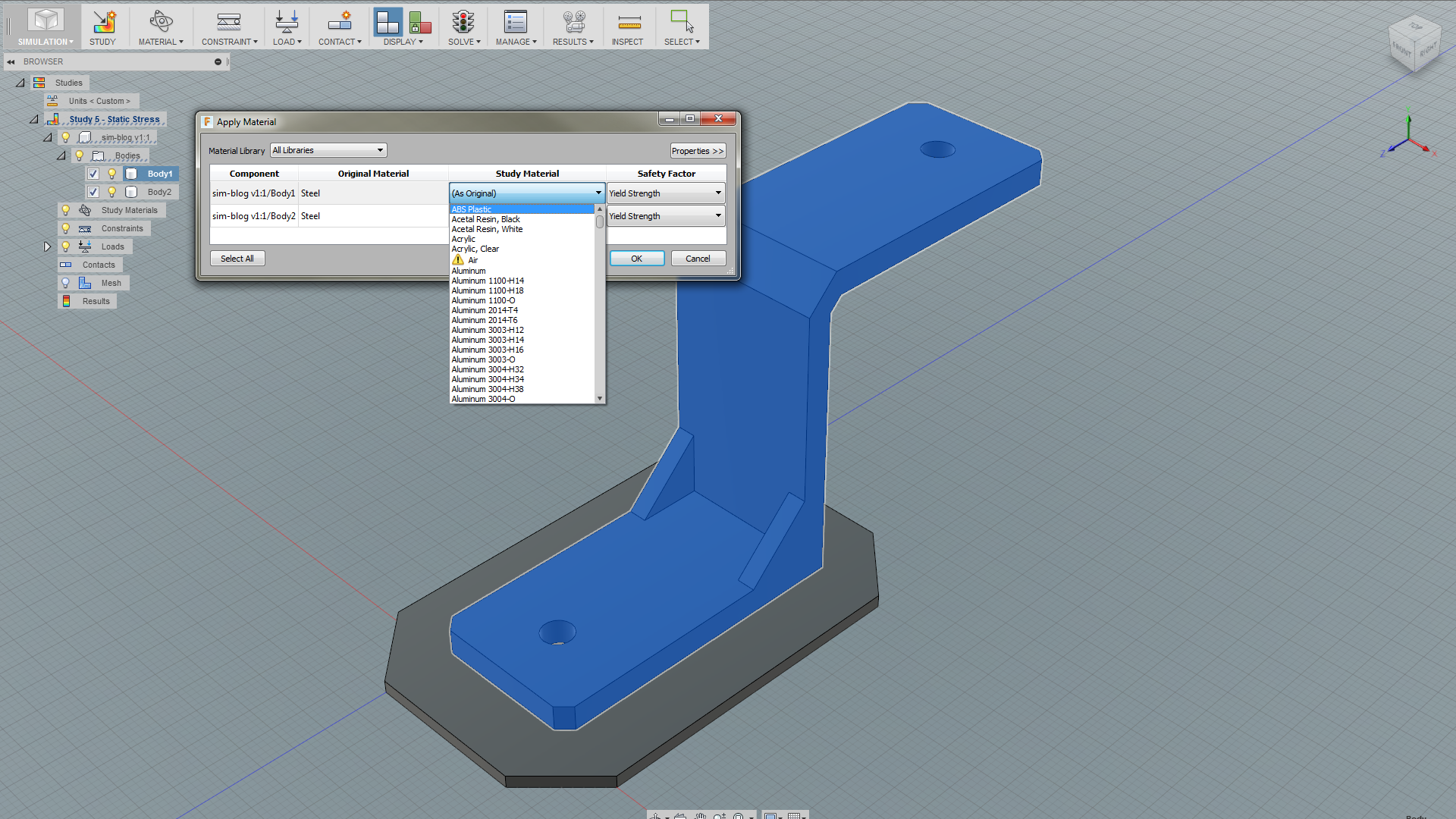
The first thing you should do is to decide what bodies/components in your assembly that should be a part of the simulation (aka. study). In the browser on the left side you can expand one of the entries (the one with the component icon) and check/uncheck which bodies/components you want to include. Here you can also select to hide certain parts.
Then you should select what material the different bodies will be simulated as (aka. study material) by pressing the Material button. There’s a LONG list of materials to choose from.
Step 2: Structural Constraints
Your simulation needs at least one constraint. Without a constraint it would be like trying to apply force on an object floating in the air or in space.
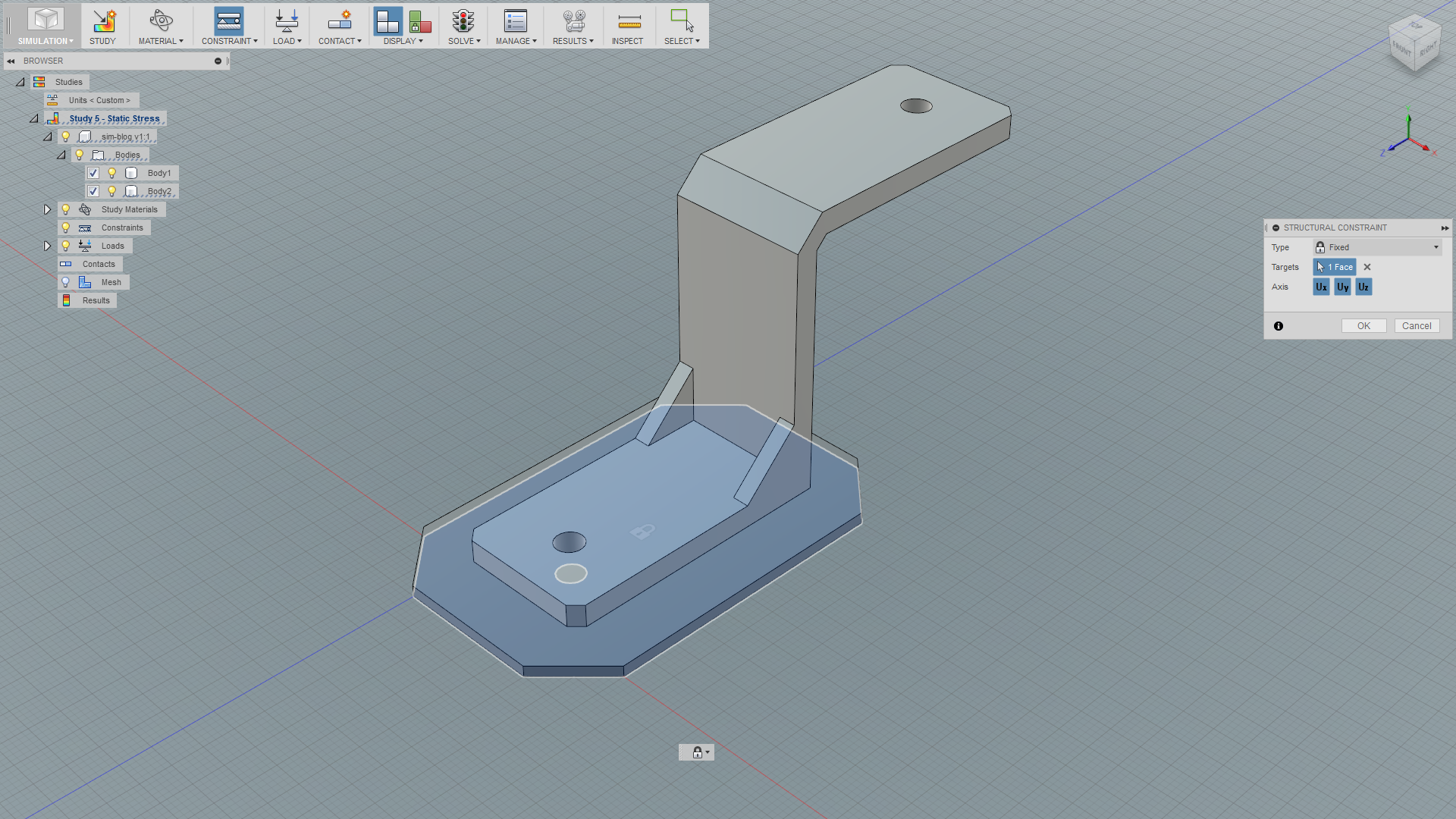
Fixed
Fixed constraint is the most basic type of constraints where you select one or more face, edge or vertex that should stick in place no matter what. You can also select which axes it should be locked along.
Pinned
Pinned constraints is applied on cylindrical faces. As with the axes in the fixed constrained type, three “subtypes” of constraints can be toggled on and off for pinned constraints: radial, axial and tangential.
- Turning the radial constraint on will prevent cylinder from moving as if you had a pin in a hole (example: insert bolt).
- Enabling the axial constraint will prevent the cylinder from sliding along the pin (example: fasten a nut).
- The tangential constraint prevents the cylinder from rotating (example: thighten the nut).
Other Constraints
You also have Frictionless constraint and Prescribed Displacement, which we aren’t going to go further into at this time.
Step 3: Load
After the constraint(s) is/are in place you should apply the load. There are several types of static load you can simulate (pressure, moment, etc.) as well as apply gravity, but we’re only going to look at force.
Force can be applied to either a single or multiple faces, edges or vertices. The magnitude must be specified (in Newtons).
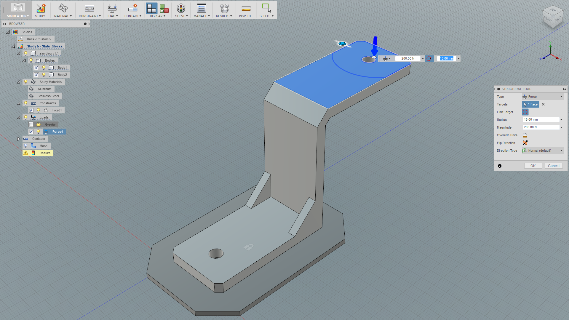
The direction can be altered using angles, XYZ vector or a reference angle (normal on a reference face or axial on a reference edge). When applying force to a face you can choose exactly where the force should be applied by using the Limit Target function. You can then also choose the radius of the area where the force should be applied.
Step 4: Contacts
This step is only necessary if you have more than one body in your simulation. The contact function defines how bodies should behave relative to eachother. These are also constraints, but unlike the structural constraints we talked about earlier, the contact constraints aren’t spatial constraints, only relative between bodies.
The easiest way to apply contacts is to select Automatic Contacts in the dropdown menu under Contact.This algorithm will create contacts between bodies that are close enough to eachother. In the settings page where you selected Static Stress in step 1 you can define this threshold (default is 0.1 mm). You can also define what type of contact which will be used in the algorithm (default is bonded).
After you’ve run Automatic Contacts you can edit the contact(s) that has been created. You can also delete some of them or add new ones. There are four types of pretty self-explanatory contacts:
- Bonded
- Separation (no sliding)
- Sliding (no separation)
- Separation + Sliding
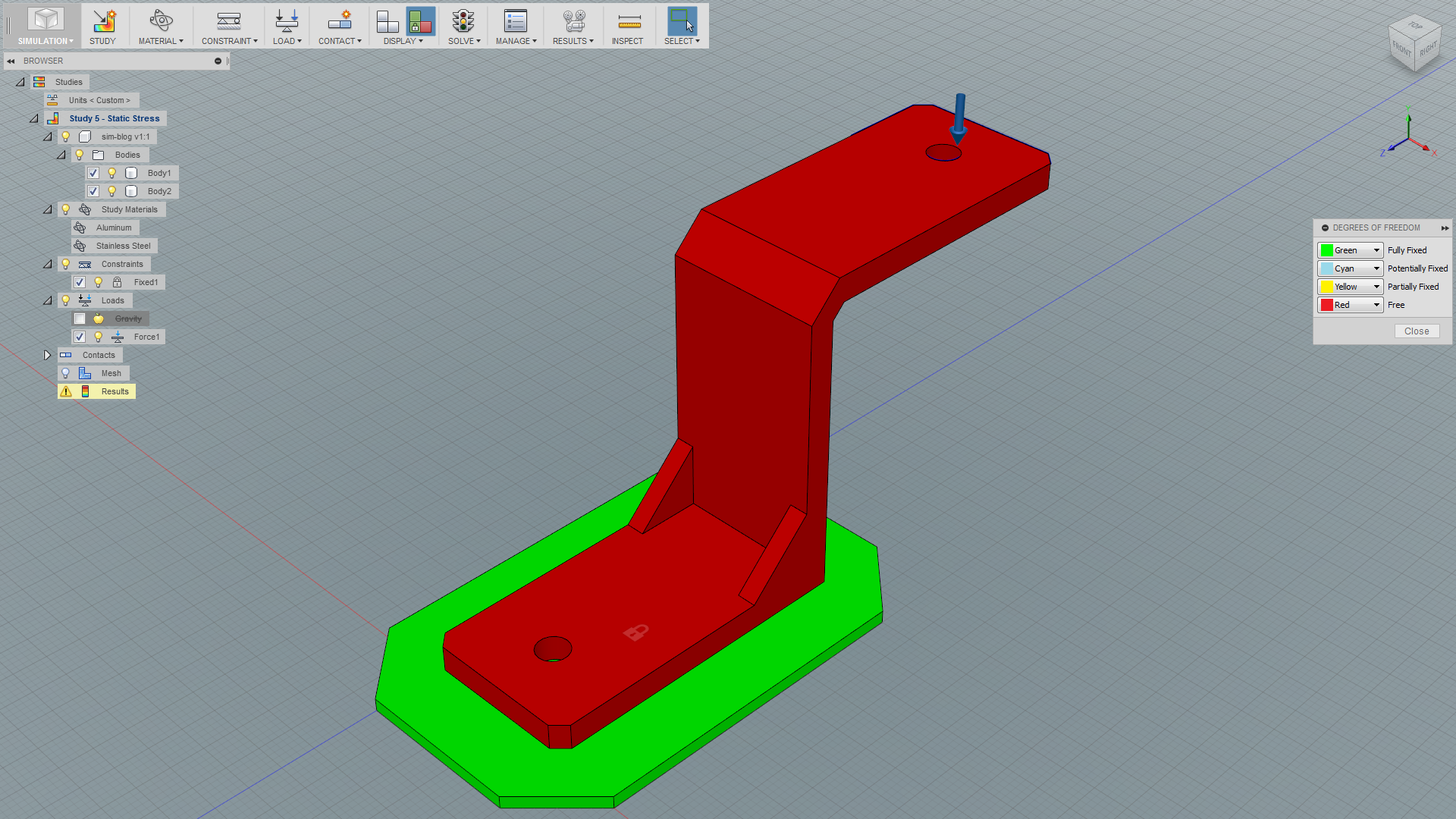
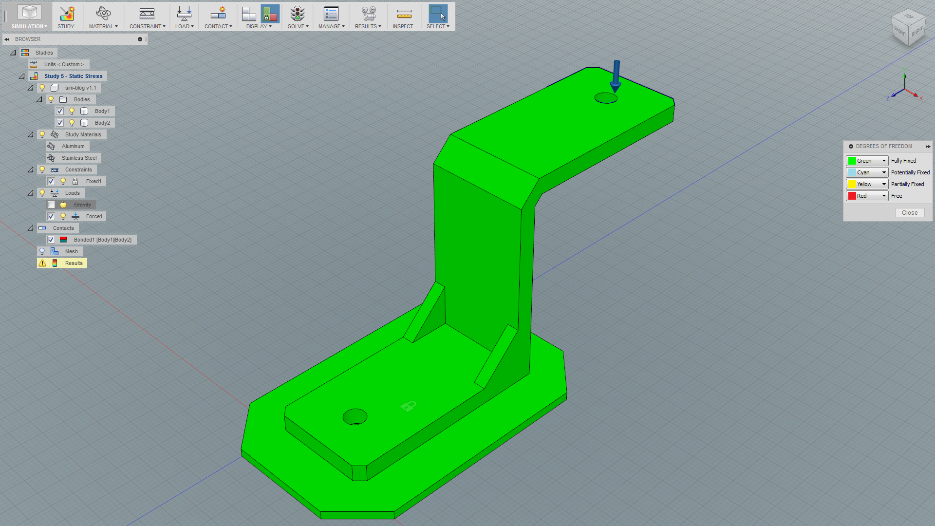
The DOF View button directly left of the Solve button lets you see if all parts are sufficiently constrained for the simulation. They should all be fully fixed (green).
Step 5: Solve
By now the Solve traffic light icon in the toolbar should have a green light. If it has, go ahead and press it and the simulation should be done in a few seconds. If it has a yellow or red light, press it anyway. You will get comprehensible error messages describing what’s wrong with your setup.
During this step the model is meshed for simulation purposes prior to the actual simulation. To get a more (or less) hi-def mesh you can fiddle with the parameters in the settings screen. The mesh visibility can be toggled on and off in the Display drop-down menu.
Step 6: Examining the Results
After a successful solve you can examine 4-5 different results:
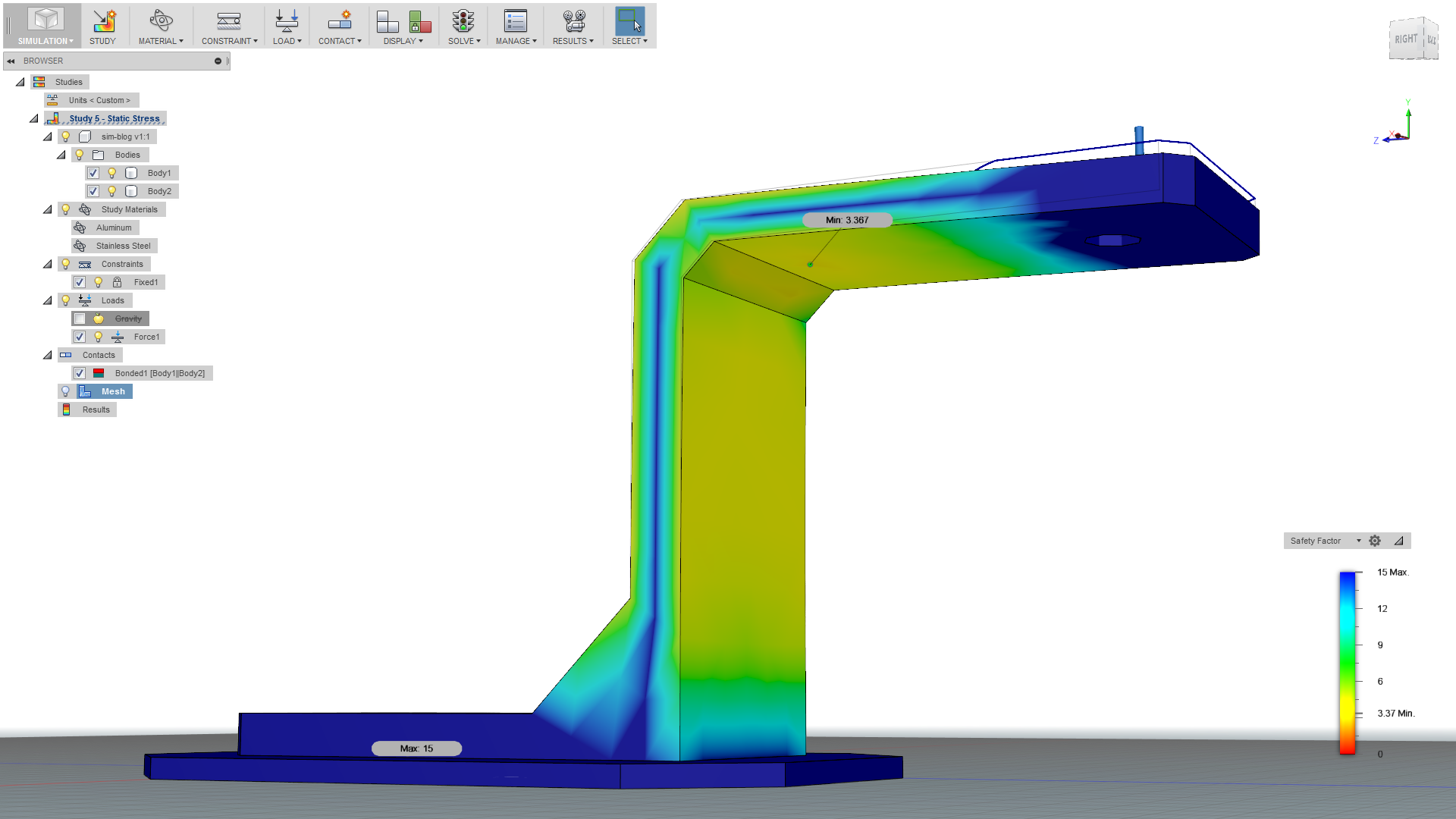
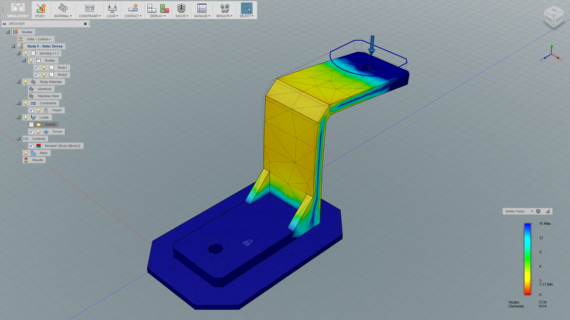
- Safety Factor – also called Factor of Safety (FoS). For typical numbers, see this page.
- Stress – a quantity of how much pressure a particle exerts on a neighbouring particle.
- Displacement – how much the body has deformed relative to its original state.
- Strain – a meassure of deformation in the material as a result of stress. Visually often quite similar to stress.
- Contact Pressure (if any) – pressure between contact surfaces.
Which one to examine is selected in the lower right corner above the vertical bar.
Deformation
The deformation is not necessarily realistic. Depending on the material, the body may snap right off where the stress is largest before being deformed as much as shown.
In the dropdown-menu under results you can find Deformation Scale. Here you can switch between none, actual or a scaled deformation.
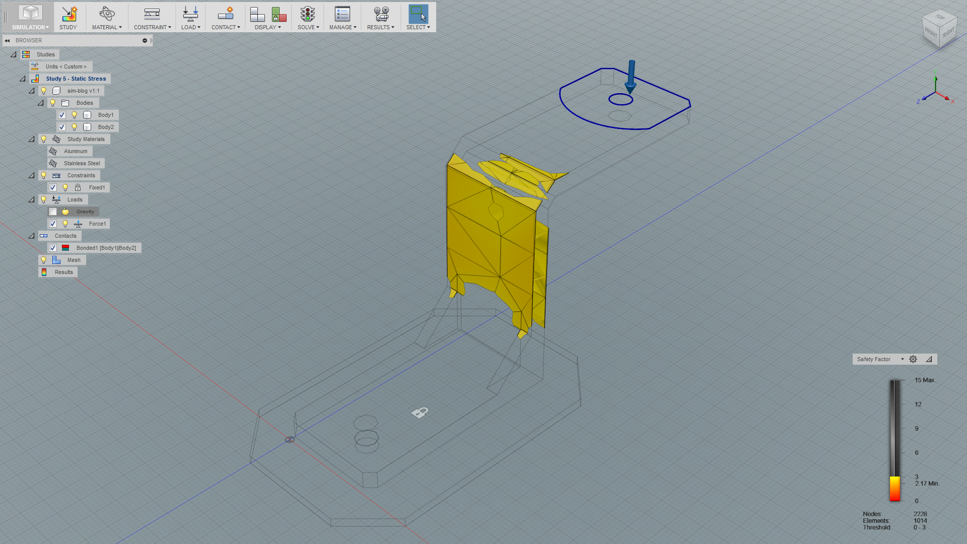
Isolating Parts of the Spectrum
By dragging the arrows on the top or the bottom of the vertical bar in the bottom right you can isolate parts of the assembly to more easily see where it is weakest and/or strongest.
Animation
Another item in the Results drop-down menu is Animate. This is a nice way to see what happens when you gradually apply more and more force up to your defined load. We recommend that you increase the number of steps and set the speed to Fastest to acheive a nice and smooth animation. You can also manually jerk around with the step slider or even make a video file for presentation.
Step 7: Improving Your Design
Let’s say that we need at least a safety factor of 3. We made the vertical part of the bracket and the upper inner chamfer 1 mm thicker and got the result in the image below.
Last Words
It’s important to simulate for a reason, and this is not necessarily as easy as it might seem. You can of course simulate for fun, and that can actually be pretty fun, but not always very useful. Knowing what to look for and tweaking your model after examining the simulation results to optimize the design takes some practice and knowledge to master.
We haven’t looked at the three other simulation modules that Fusion 360 offers:
- With modal frequencies you can see under which frequencies your model will start behave wierdly, and how it will behave (for instance if you place it in front of a speaker). These frequencies are best avoided in the real world if your part is fragile (for instance thin glass).
- Heat simulation lets you for instance design optimal heat sinks. You can see how heat is transferred and dissipated along and between bodies.
- Thermal stress is a combination of heat simulation and static stress simulation.
We hope this post was useful to you. Mechanical simulation is a wide scientific field and we aren’t experts in this field, so we tried to keep things basic without going into too much detail.