In this blog post we’ll show you how to create wires and tubes in different ways. We’ll start with laying everything on a flat surface, then on an uneven surface and lastly mix things up a bit more.
These methods and principles will also probably work in other CAD programs, given they have similar tools, of course.
Flat Surface
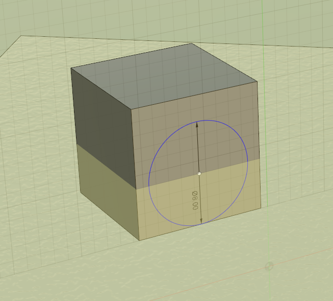
In this example we’ll create an 8 mm outer diameter tube with 1 mm walls which just lays on a flat surface.
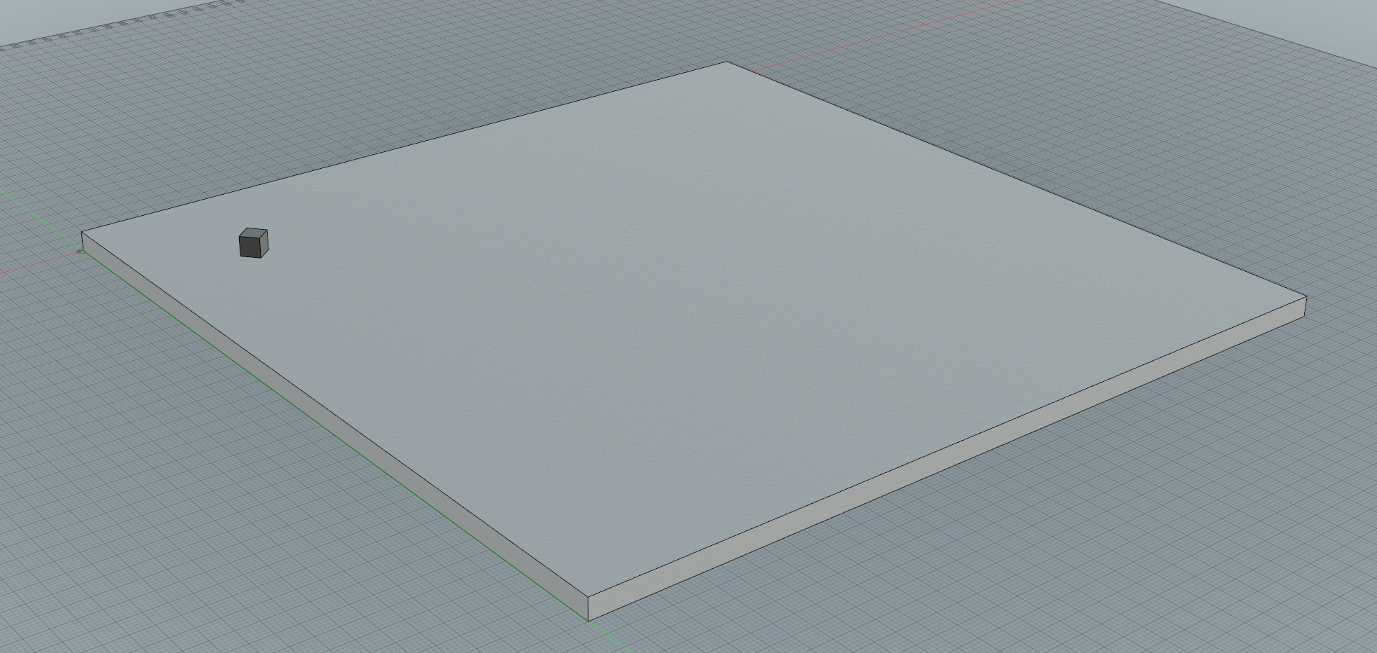
First, create a flat surface in the form of a box. Then create a smaller cube with sides large enough to house the cross section of your wire or tube. For our Ø8 mm tube, we’ll just create a 10x10x10 mm cube. This cube is not necessary, but it makes it easy to define a start position and angle. It will also underline an important technique later on. Usually you would have a set place to start and end your wire/tube, but in this case we don’t have anything like that.
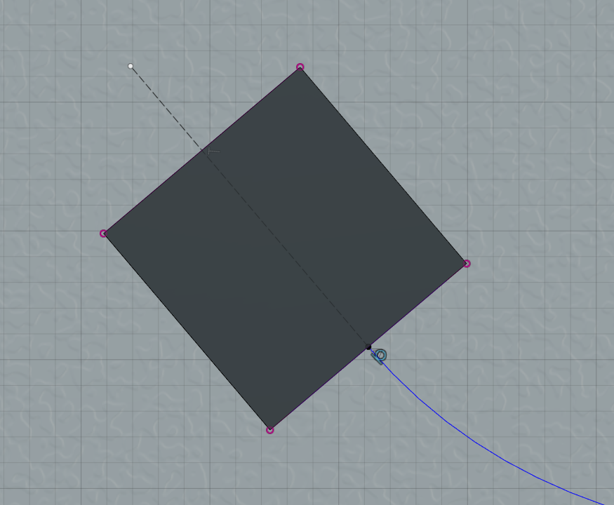
Then construct an offset plane above the large surface with offset equal to your wire/tube radius. In our case this is 4 mm. In addition, create a sketch on one of the sides of the cube where you want your wire/tube to start. Create a circle tangent to the bottom edge as in the screenshot below. This will serve as our sweep profile.
Next, create a spline on the offset plane which starts at the center-point of the proper side of your cube. The shape is not that important, but it will reflect the physical properties of your wire/tube – stiff as a garden hose or soft as boiled spaghetti. Don’t worry about the spline being perpendicular on the cube edge yet. What you also can do is to create a straight construction line on the same sketch which starts where the spline starts and goes through the cube. This should be perpendicular to the cube edge/face.
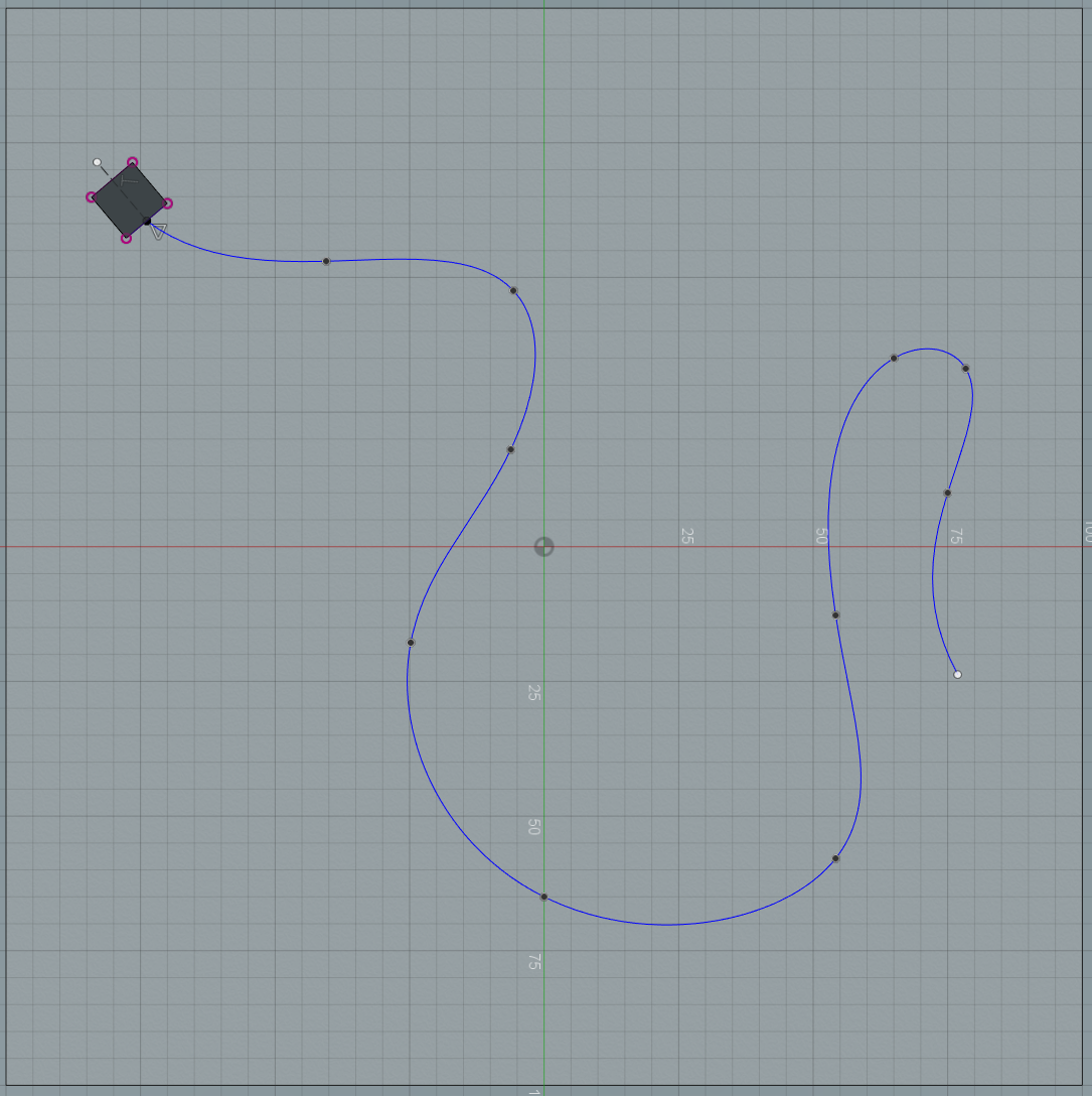
Here comes a neat little trick: create a tangent constraint between your spline and your straight construction line. This way your wire/tube will start in a natural angle relative to what it is attached to. It doesn’t matter too much in our example here, but you more often than not want your wire/tube to exit perpendicularly out of a box or whatever. You can also play around with the spline’s fit points while the start will stay in the same angle in a natural fashion.
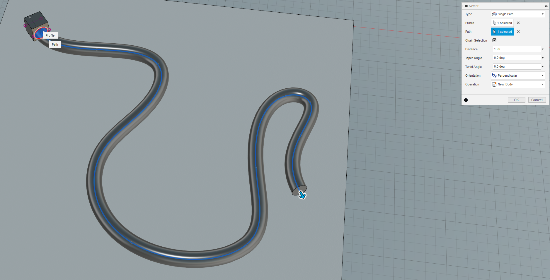
Now comes the fun part! Use the sweep tool and choose the circle on the side of the cube as profile and the spline as patch. Make sure orientation is Perpendicular and that you choose either new body or new component as operation.
To make this thing look less like a smoothly bent steel rod and more like a tube, use the shell tool. Select both ends and specify wall thickness (in our case 1 mm). This will hollow out our steel rod and make it a pipe instead. Alternatively, you can create to circles on the side of the cube (one for the outer diameter and one for the inner) and use the area between them as the sweep profile. This way you don’t have to use the shell command.
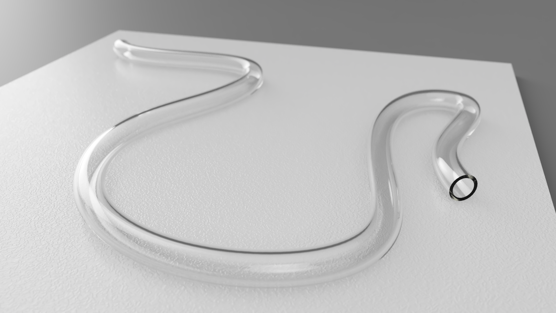
Give it the clear acrylic appearance and do a quick render. Remember to hide your cube! The result might look something like this:
You can easily change the shape of the tube by moving/adding/removing spline fit points in the sketch. The changes will propagate to the final result. The outer diameter can be changed by altering the circle diameter on the side of the cube. For it to rest on the surface you will need to go change the offset plane offset.
Uneven Surface
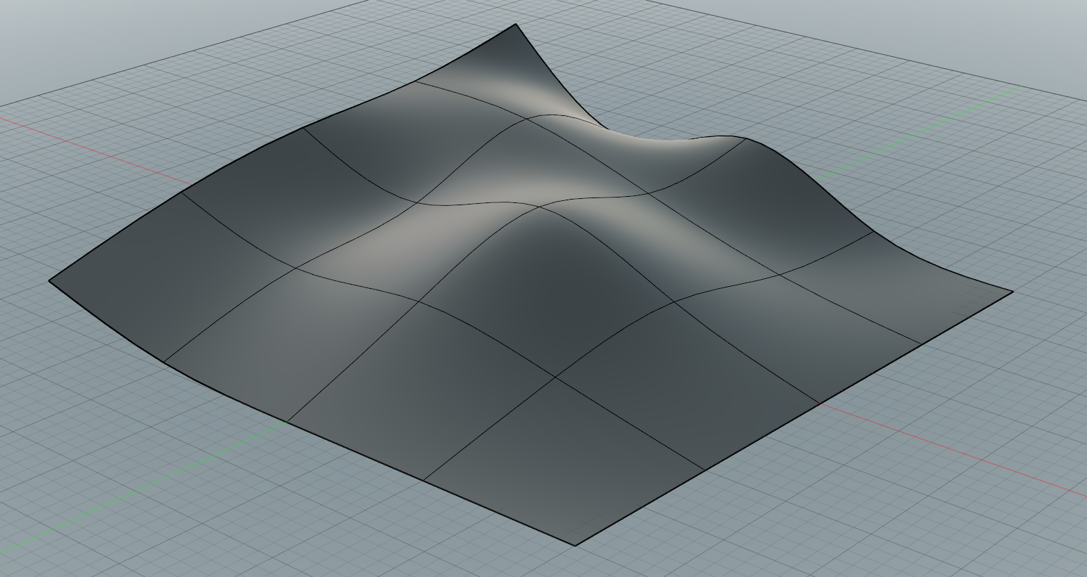
Let’s up the complexity a bit. This principle works with any kind of surface, but in this example we will use the sculpting environment to create the uneven surface and go from there.
Start with creating a form. This will take you to the Sculpt workspace. Create a plane with as many faces as you feel like and make it “un-flat” by using the Edit Form tool (drag vertices, edges and/or faces up and/or down). We found our inner artist and created the magnificent wavy surface seen below.
Now we’re going to use the handy Thicken tool to create two additional surfaces based on this one: one surface which the center of the tube will follow and another surface which actually will thicken the original surface and create a solid body.
The cool thing about the Thicken tool is that a surface can be thickened either along an axis or along the normal of the surface. We will need to use the Normal direction for the plane that the tube will follow and the No Edge thicken type. Choose a thickness equal to the radius of your tube. In our case this is still 4 mm.
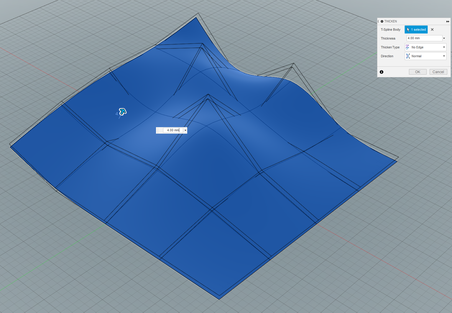
Repeat the operation, only this time reverse the direction, choose either a Sharp or Soft thicken type. The direction parameter and the thickness aren’t important (we went with Sharp, Normal and 1 mm).
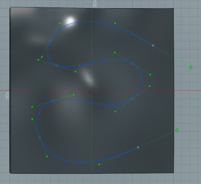
Create a sketch in the XY plane (if the Z-axis is your vertical axis) and draw your initial tube shape with a spline. Our sketch can be seen below.
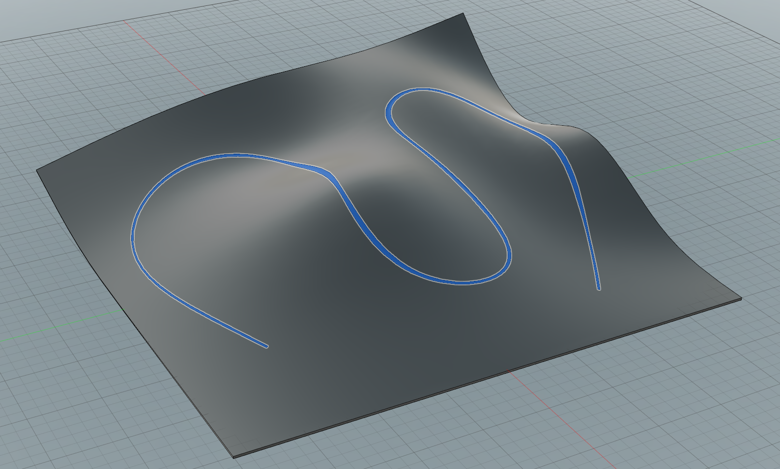
Now create a new sketch and choose the Project To Surface tool. This is where the magic happens. Choose the topmost surface as face, the spline as the curve and the vertical axis as projection direction with an Along Vector project type. You can see the result below where the spline follows the chosen surface.
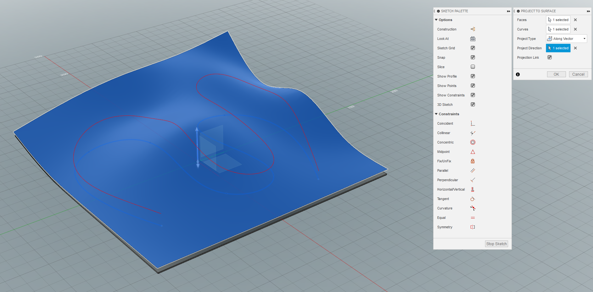
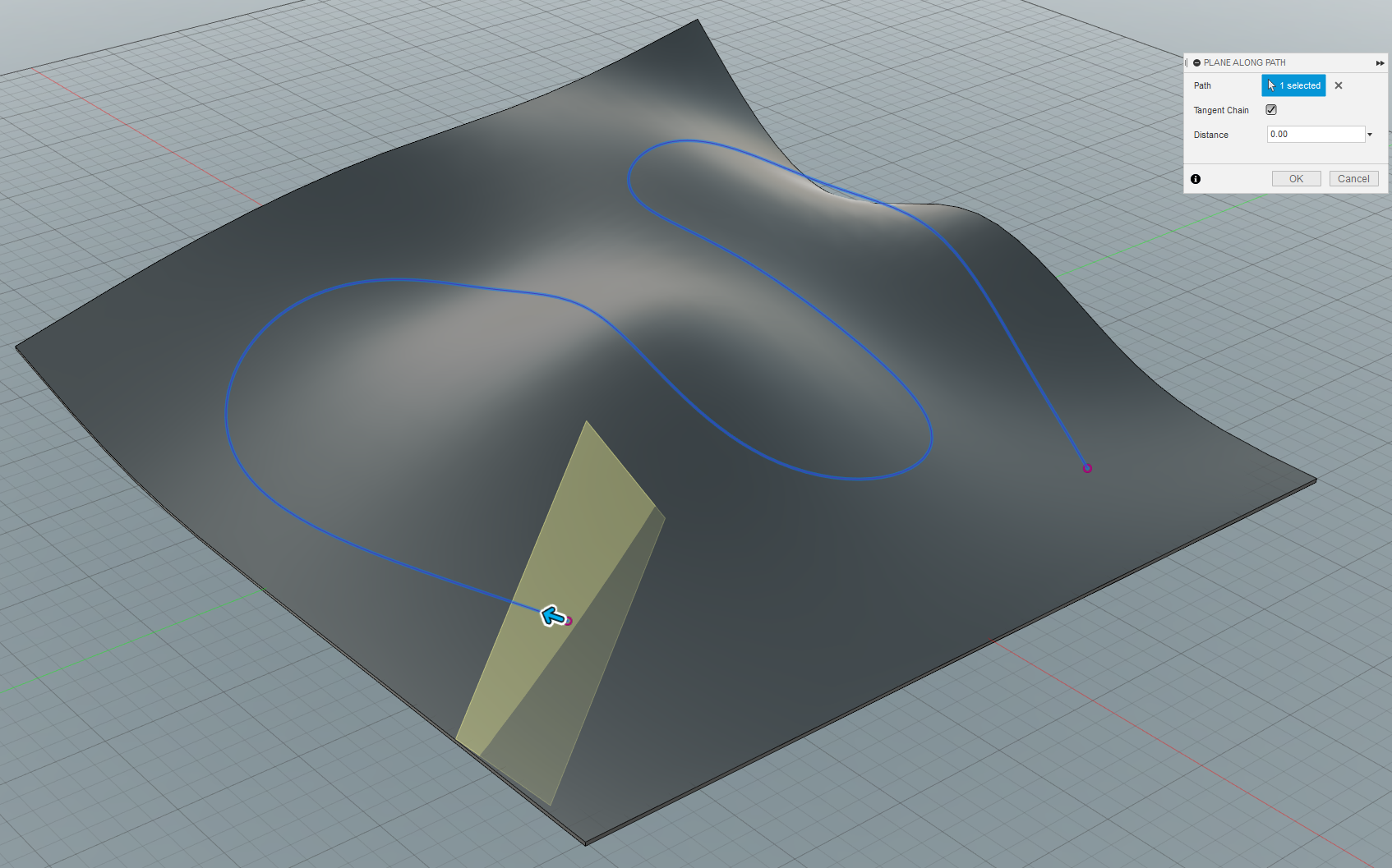
In the first example we used a cube to define the sweep profile. This time we’re going to do something different. Construct a plane along path, choose the newly projected curve and drag the plane to one of the ends of the curve like seen below. The curve will always be normal to this plane. Hide the topmost surface (you won’t need it anymore).
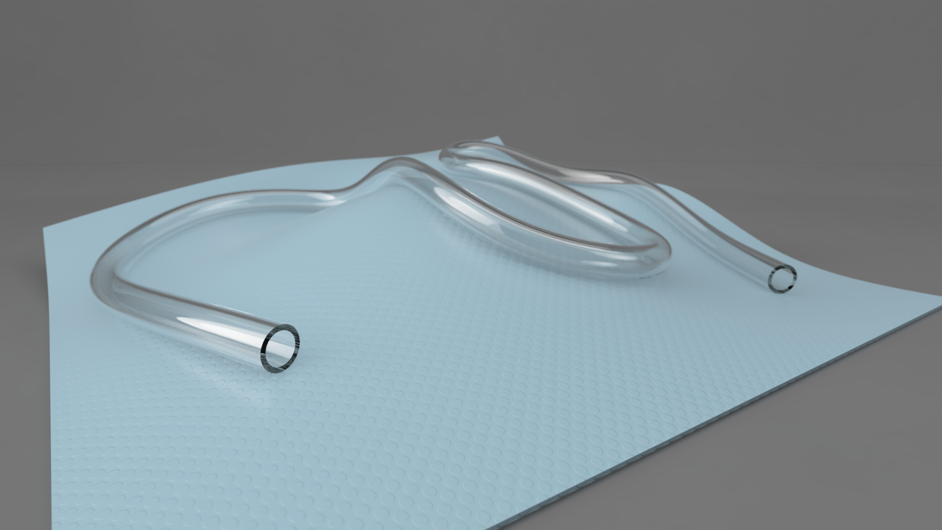
The rest is easy. Create a tube profile on the newly constructed plane with correct outer radius and use the sweep tool to create the tube.
One issue you might encounter is that the tube may cut into the base surface. This is in our opinion not logical since the target surface for the projection should at any given point be exactly one tube radius away from the base surface. If some of you know why this isn’t the case, please leave a note in the comments below.
Luckily, this amount isn’t that large. You can see below how much got cut into our base surface. For pure aesthetic purposes, this can be overlooked. We chose to cut away the overlapping part.
Now, put on some silly textures and render. Here’s our result.
Air Time
Up until now, our wires/tubes have followed the surface completely. This makes it look very soft and/or heavy. Smaller wires and tubes are usually quite stiff compared to their weight, and will be floating much more in the air.
Here’s an example where we have added a bit more natural stiffness, but it still looks quite soft and heavy.
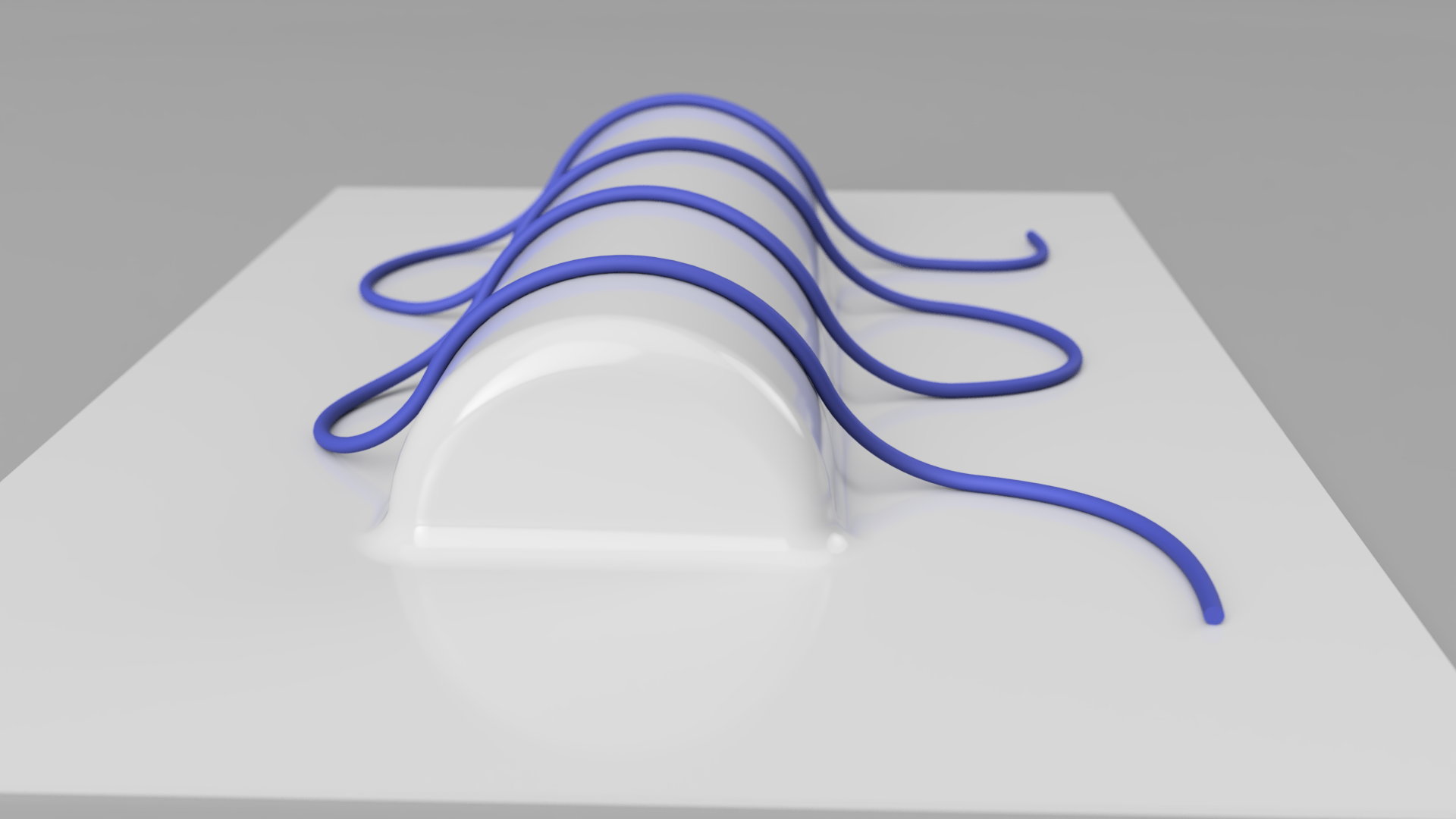
Here we have used the same approach as the previous example except deviated a bit more from the original surface. What we did here was pretty simple due to the simplicity of the original surface:
- Make a copy of the original body and enlarge it in a normal direction (larger diameter on the cylinder and a bit thicker flat area).
- On the larger body, increase the fillet radius on the sides of the cylinder. This will make the wire/tube float a bit in the air where it’s somewhat natural.
- Project to surface and sweep just like before.
3D Sketching
Combine what we’ve talked about up until now with 3D sketching, and you’ll have a powerful set of wire/tube making skills. For this to work you need to check the Allow 3D sketching of lines and splines box in the Design preferences. Now you can for instance create a spline on a sketch and manually drag the spline fit points away from the sketch plane, creating a three dimensional spline.
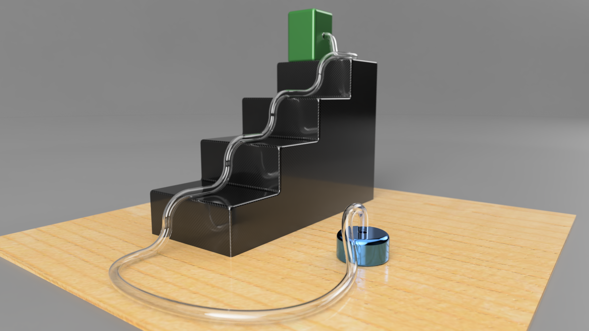
In the render at the very top of this blog post we’ve used a combination of all these methods and principles. We’ve combined splines projected to surfaces and 3D splines. Combining these in a smooth way can be a bit tricky sometimes, but give it try! Learning by doing doesn’t get old.