In the previous part of this series we gave you an intro to Boolean algebra and Logic Gates, which incidentally happens to be the title of this blog post as well.
This time around we’ll take things a bit further and introduce you to latches and flip-flops.
Latches vs Flip-flops?
Latches and flip-flops are circuits consisting of logic gates with one, two or three inputs which stores information
Latches
A latch is asynchronous, which is the simple type. We can say that latches are level triggered. This means that it’s only the reguler inputs which control the output as opposed to any timing-based input.
Flip-flops
Unlike Latches, flip-flops have a clock input, which makes them synchronous. The output can only change at a positive or negative flank, i.e. when the clock changes state. In total, flip-flops have three inputs.
Different Types of Latches
Let’s look at a few different latches and flip-flops and their functions.
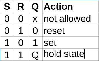
SR NOR Latch
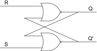
SR Latches are the most basic latches. This layout has feedback, which is a key aspect of latches. Q’ is the same as NOT Q. Thus you actually only need one of the outputs to see the behaviour of the latch.
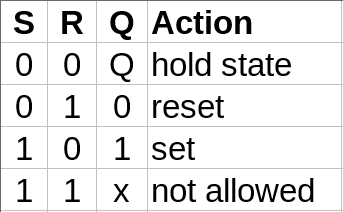
What’s special about this behavior is the case where both inputs are low. It will then just keep the outputs at the same state. This is the core concept of latches and flip-flops.
SR NAND Latch
You can make a similar behaviour with NAND gates.
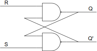
As you can see, we’ve just swapped out the NOR gates with NAND gates.
The only difference in behavior from the SR NOR latch is the swap of the upper and lower lines.
JK Flip-flop
Let’s up the complexity a bit.
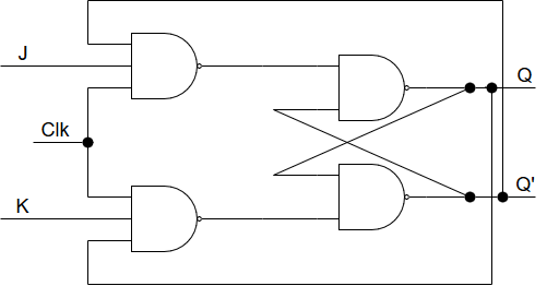
Here we have an additional couple of NAND gates as well as even more feedback. Also, notice the clock input. See the table below for the behavior.
We’ve added dots in the nodes (junctions) in this schematics to clarify things a bit. These are the smallest dots we found.
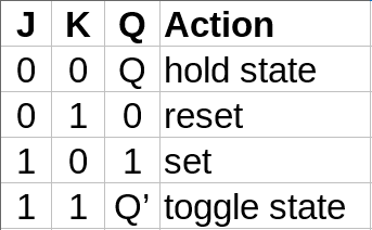
This behavior is similar to the SR latches, except for the toggle state.
This JK flip-flop layout changes output state when the clock changes from low to high.
T Flip-flop
If we combine J and K inputs in the JK flip-flop into a single input called T and keep everything else as it is, we get what we call a T flip-flop aka. toggle flip-flop with the following simple truth table:
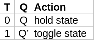
Just like the JK flip-flop nothing happens between either positive or negative clock edges. It’s the clock that triggers the logic.
This behavior can also be described with the following equation: Qnext = T XOR Q.
D Flip-flop
This flip-flop is a bit different from the others. It is also known as data flip-flop or delay flip-flop. The flip-flop below is a positive-edge-triggered D flip-flop.
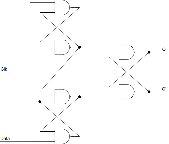 Firstly, this flip-flop only has one input in addition to the clock.
Secondly, the main purpose of this flip-flop is basically to hold the data signal until the next falling or, in this case, rising clock edge.
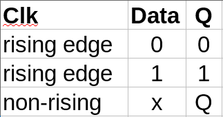
In this case, x means that the flip-flop doesn’t care what the data is.
D flip-flops form the basis for shift registers, which are fundamental parts of many electronic devices.
Summary
These are just a few of the common latches and flip-flops to chose from.
To summarize: flip-flops are triggered by a clock signal, latches or not. The feedback in the designs gives these latches and flip-flops their instinctive behavior.
Later, we’ll look into more cool things you can do with flip-flops, latches and logic gates in general, both in real life and in theory.