When designing embedded systems, you more often than not should implement a proper state machine of some sorts. In this blog post we’ll explain what state machines are, compare a couple of types, look at the handy Huffman table and show you one way to implement a simple state machine on an Arduino.

What Is a State Machine?
A state machine it’s not a machine in the same way that a lawn mower or a typewriter is a machine. It is more of an abstract concept or system that helps you systematically design and implement the logic behaviour of an embedded system. In fact, the state machine concept is so abstract that you can use it to much more than just embedded system logic, but in this post we’ll concentrate on state machine usage for embedded systems.
To create a state machine you need a set of states, inputs and outputs.
States
An embedded system should at any given time be in a defined state, whether it is “moving left”, “door open”, “stopped”, “init”, “error” or any other imaginable state. The states and the transitions between them make up the main structure of the state machine.
Inputs
Inputs are what makes the system switch states and can for instance be switches, buttons and sensors or any other typical embedded input.
Outputs
Outputs in a state machine can be motor movement, lights or any other typical embedded output.
Mealy vs Moore
There are two main types of state machines: Mealy and Moore. The main difference is that the Moore machine defines the outputs within each state, while the Mealy machine triggers outputs when transitioning from one state to another. This might seem like two ways of doing the exact same thing, but Mealy machines actually tend to have a less amount of states than Moore machines (on average).
An Abstract Example Comparing the Two
Here’s an example taken from this excellent YouTube video where the Mealy machine ends up with less states than the Moore machine.
This system takes in a stream of zeros and ones and outputs a 1 any time it gets the input sequence 011.

In both diagrams, the bold numbers in the state bubbles represent the name of the states. In the Moore diagram, the lower numbers in the state bubbles are the output while the numbers on the arrows are the input. In the Mealy diagram the numbers on the arrows are in the form of input/output.
As you can see, the Mealy machine ends up with a state less states since the Moore machine needs a seperate state where it sets the output to 1.
The Huffman Table
The Huffman table is a neat way to catch all logic cases for each state. The rows are states and the columns are inputs or combinations of inputs. The contents of the cells are in the form of next state/output.
Example
Let’s imagine a vehicular robot almost like a Roomba that can rotate around its own axis. It will travel straight until it almost hits a wall. Then it will stop, and rotate until it’s unable to detect the wall and start moving forward again.
Let’s say it has two IR sensors near the front, aiming 45 degrees to either side. If both sensors are triggered, it will rotate to the right.
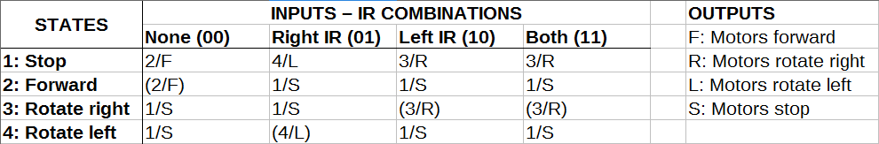
If we put this into a Mealy machine, it’ll look something like this:

The need of the Stop state is debatable. It’s merely a transition state, but we included it to make things a bit more lucid.
Arduino Implementation
Let’s give it a shot to code a state machine for our beloved robot. There are many ways to implement state machines. One way is to create a lookup table in your code like the Huffman table, but that quickly turns into a debugging mess.
Below is another way to implement the state machine for the robot. It uses a switch case statement for the states. Within each case (state) we decide what to do based on what we have on the sensor input.
enum State_enum {STOP, FORWARD, ROTATE_RIGHT, ROTATE_LEFT};
enum Sensors_enum {NONE, SENSOR_RIGHT, SENSOR_LEFT, BOTH};

void state_machine_run(uint8_t sensors);
void motors_stop();
void motors_forward();
void motors_right();
void motors_left();
uint8_t read_IR();

uint8_t state = STOP;

void setup(){
}

void loop(){
  state_machine_run(read_IR());

  delay(10);
}

void state_machine_run(uint8_t sensors)
{
  switch(state)
  {
	case STOP:
	  if(sensors == NONE){
		motors_forward();
		state = FORWARD;
	  }
	  else if(sensors == SENSOR_RIGHT){
		motors_left();
		state = ROTATE_LEFT;
	  }
	  else{
		motors_right();
		state = ROTATE_RIGHT;
	  }
	  break;

	case FORWARD:
	  if(sensors != NONE){
		motors_stop();
		state = STOP;
	  }
	  break;

	case ROTATE_RIGHT:
	  if(sensors == NONE || sensors == SENSOR_RIGHT){
		motors_stop();
		state = STOP;
	  }
	  break;

	case ROTATE_LEFT:
	  if(sensors != SENSOR_RIGHT)
	  {
		motors_stop();
		state = STOP;
	  }
	  break;
  }
}

void motors_stop()
{
  //code for stopping motors
}

void motors_forward()
{
  //code for driving forward
}

void motors_right()
{
  //code for turning right
}

void motors_left()
{
  //code for turning left
}

uint8_t read_IR()
{
  //code for reading both sensors
}
Concluding Words
When designing embedded systems, the logic quickly becomes complex, disorganized, and bewildering. You might eventually be able to get the logic to work with a mess of a code, but debugging will give you gray hairs and the code will possibly be near incomprehensive to others.
With state machines you get the proper overview, both in terms of documentation and code. Debugging becomes a lot easier too. When filling out the Huffman table you quickly see what cases you haven’t thought of and are able to make a complete ruleset of every possible case.