Four weeks ago we wrote about a 3D printer we’re building. Now we have started building it, and we thought it’d be cool to share some of it in this post.
Various Discussions and Pictures of Stuff
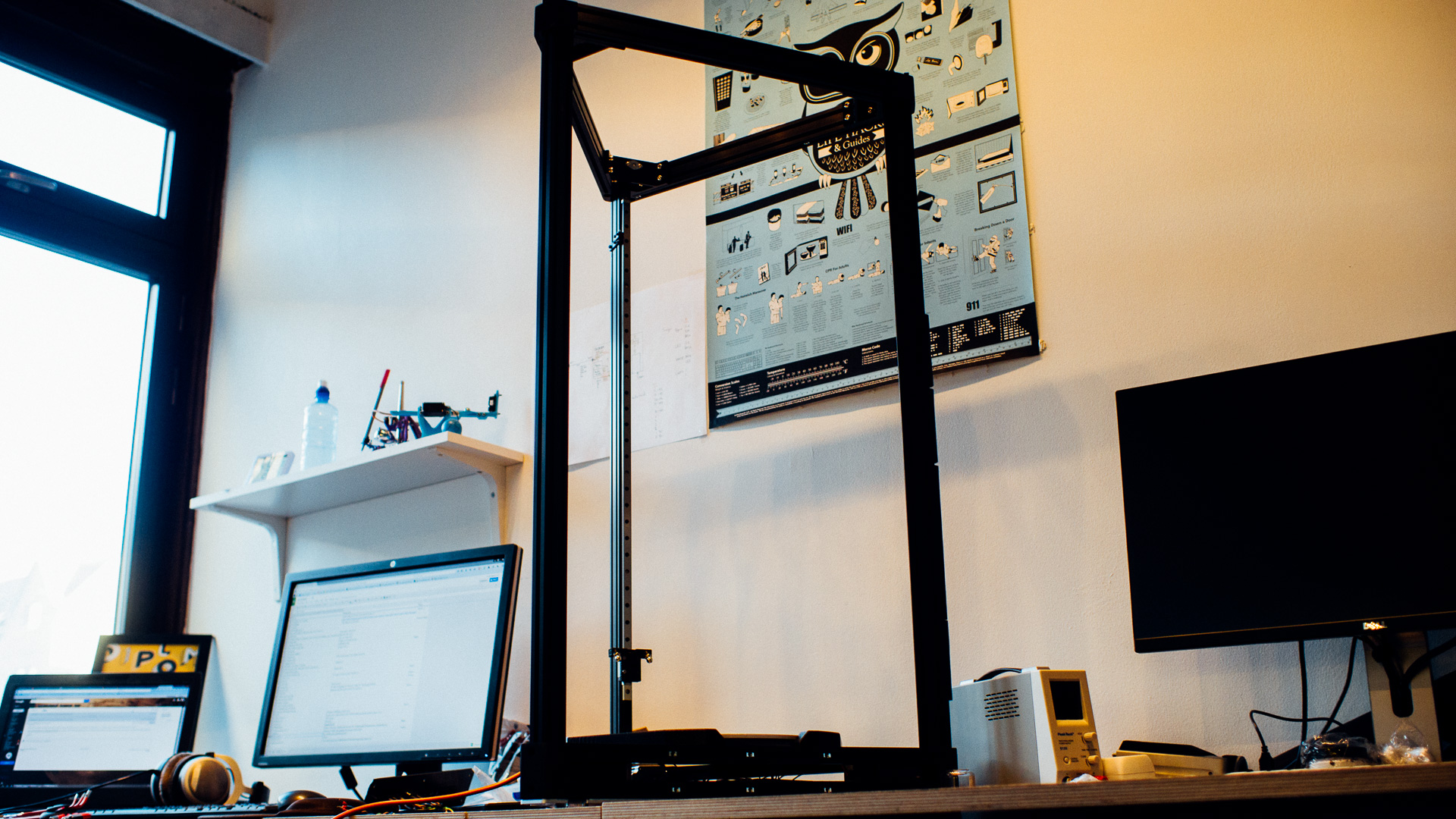
This thing is massive! It’s not easy to get the right impression from the image above. The total height is 1 meter and the sides are over 0.5 meters long.
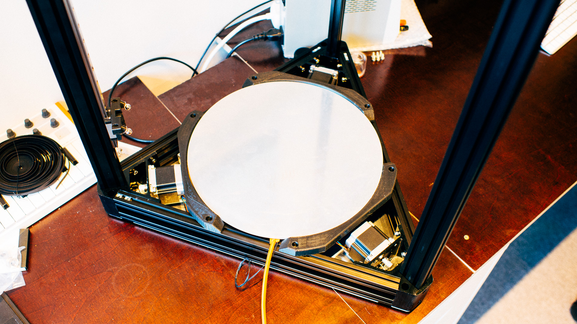
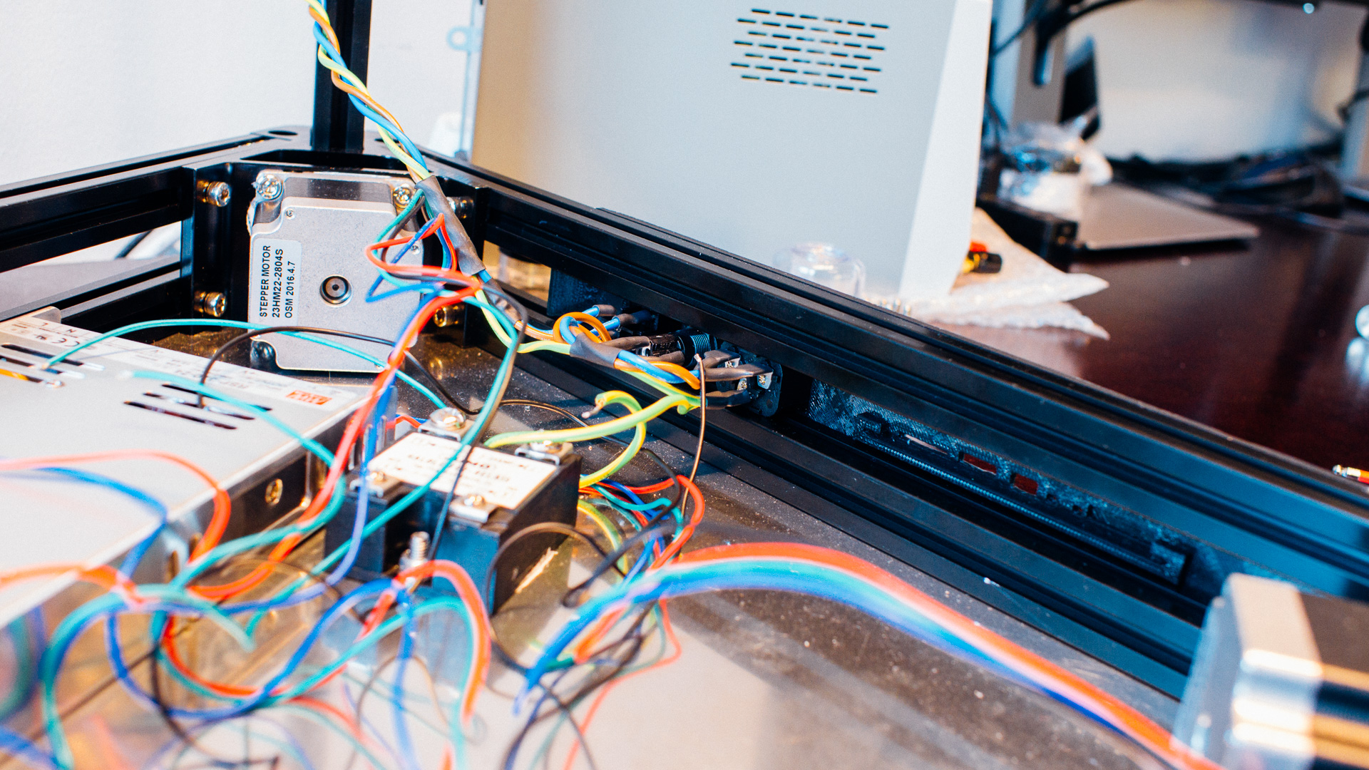
We have done most of the base assembly. The frame and baseplate is in place as well as the stepper motors, PSU and SSR.
The baseplate and aluminium build plate turned out perfect. They were laser cutted by one of these bad boys.
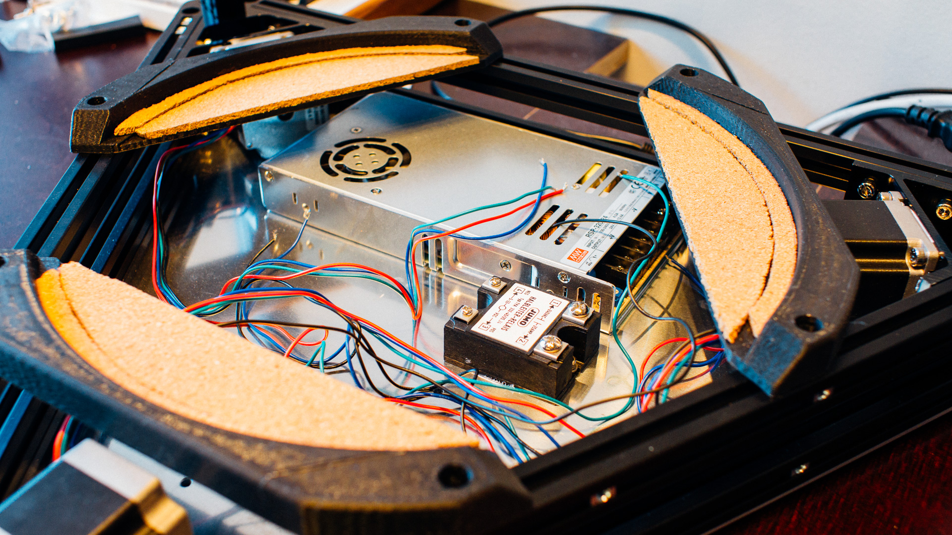
We’ve mounted the SSR and stepper motors with thermal paste for better cooling.
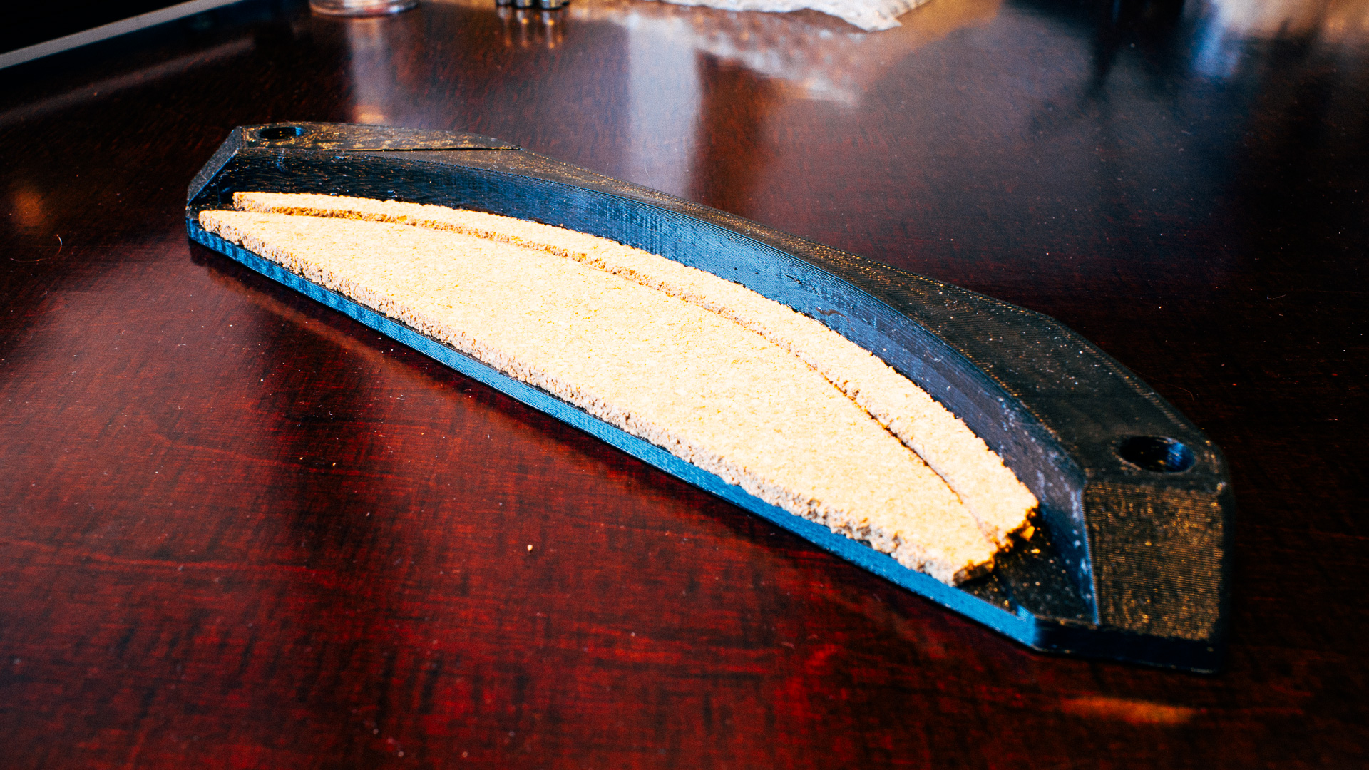
As shown in the two images above, we’ve glued 4 mm cork sheets to the build plate brackets to protect them from the heat.
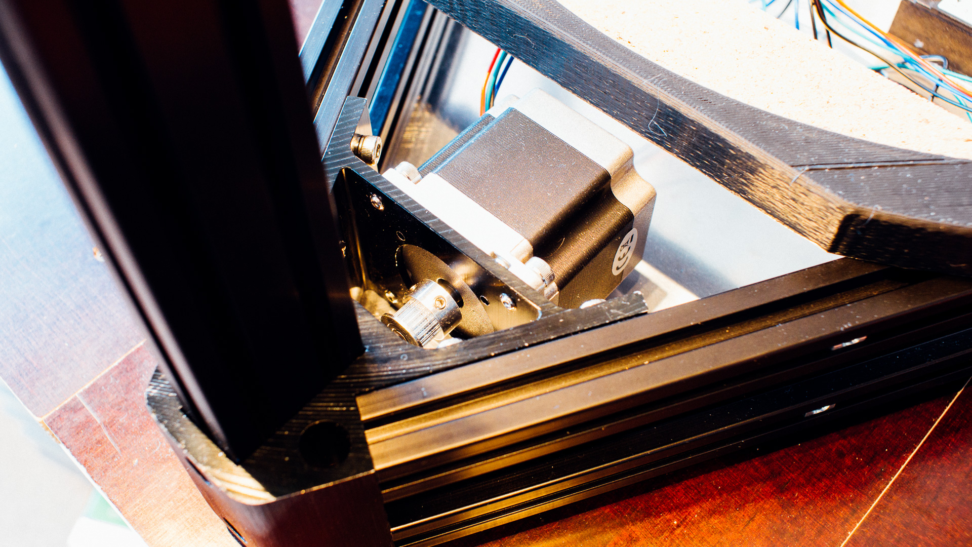
The NEMA 23 stepper motors we ordered had 6.35 mm (1/4 “) shafts. We only had pulleys with 5, 6 and 8 mm bore, so we asked the workshop at the Department of Engineering Cybernetics at NTNU to resize the 6 mm ones. They were happy to help, and used a lathe to make them fit perfectly. Thank you! 🙂
The stepper motors were really easy to mount thanks to the threaded holes in the corners from RobotDigg.
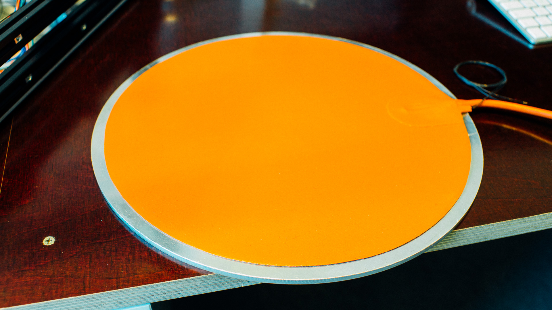
We haven’t tested the heater yet, but we’ve attached it to the aluminium and got it adequately centered.
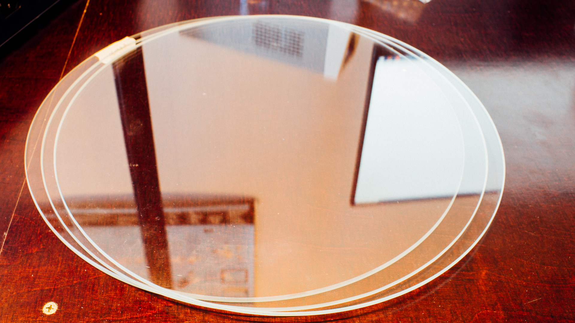
The borosilicate glass plates were a bit uneven in the cuts. Luckily we’d ordered one extra since only two of them were acceptable.
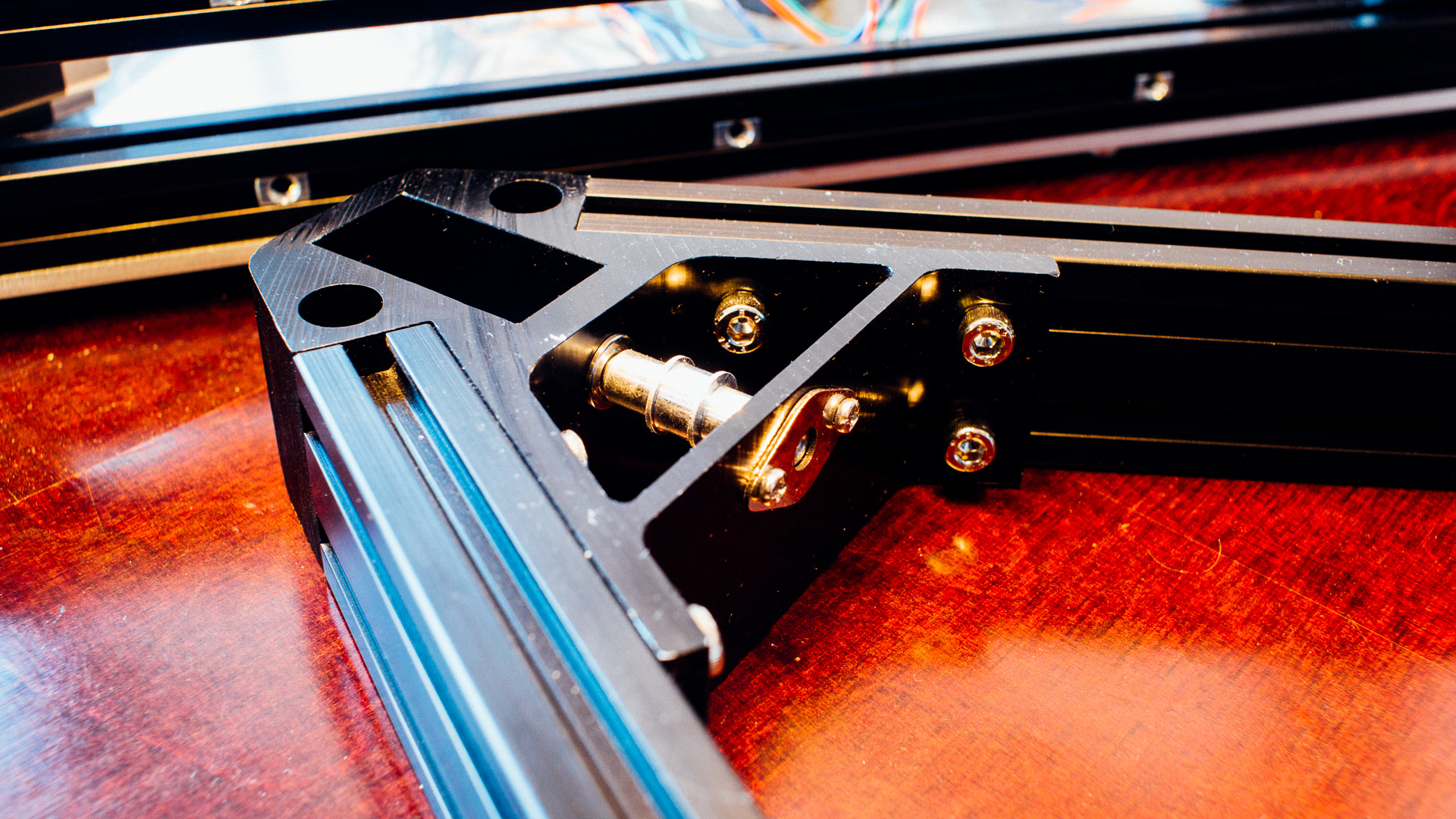
The carriage brackets will be the link between the guide rails and the rods, as well as the place where the belt is locked tight.
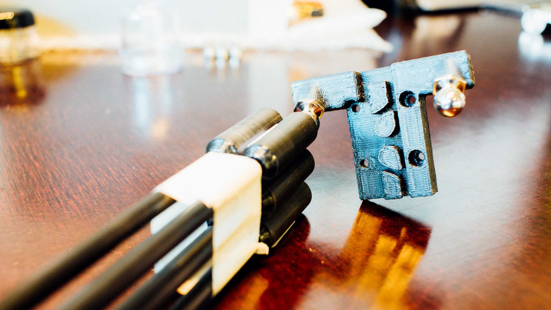
The bracket design is a redesign of several other designs that does the exact same thing.
We are not particularly happy with the guide rails themselves. We got three 800 mm rails with carriages from RobotDigg, and only one of them has acceptable bearings. The other two feels really jagged when moving them by hand. Despite being Chinaware we expected more for the price ($129 + shipping). We’ll try to get them replaced with two that move properly. We would’ve ordered them from Misumi or Hiwin if they weren’t so insanely expensive.
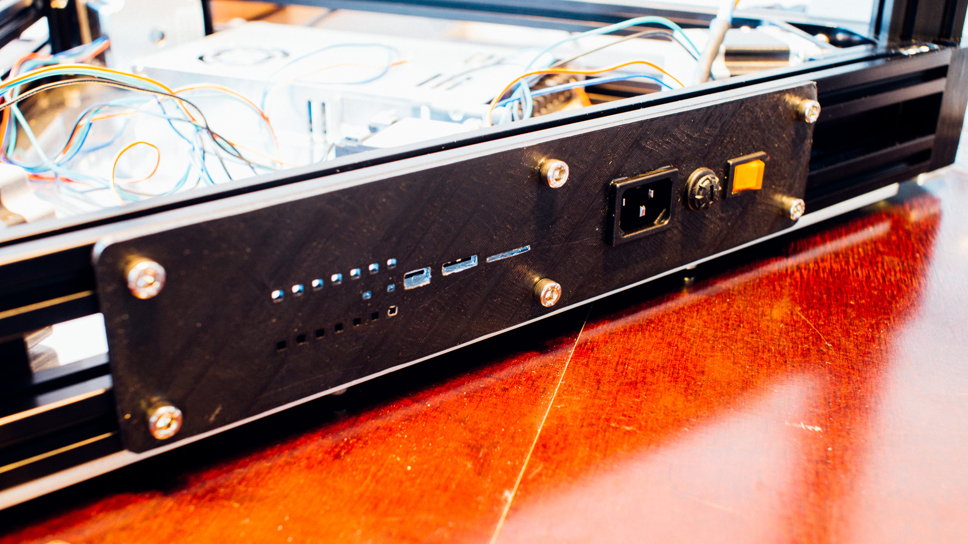
This is the electrical panel we’ll use. We found the design here.
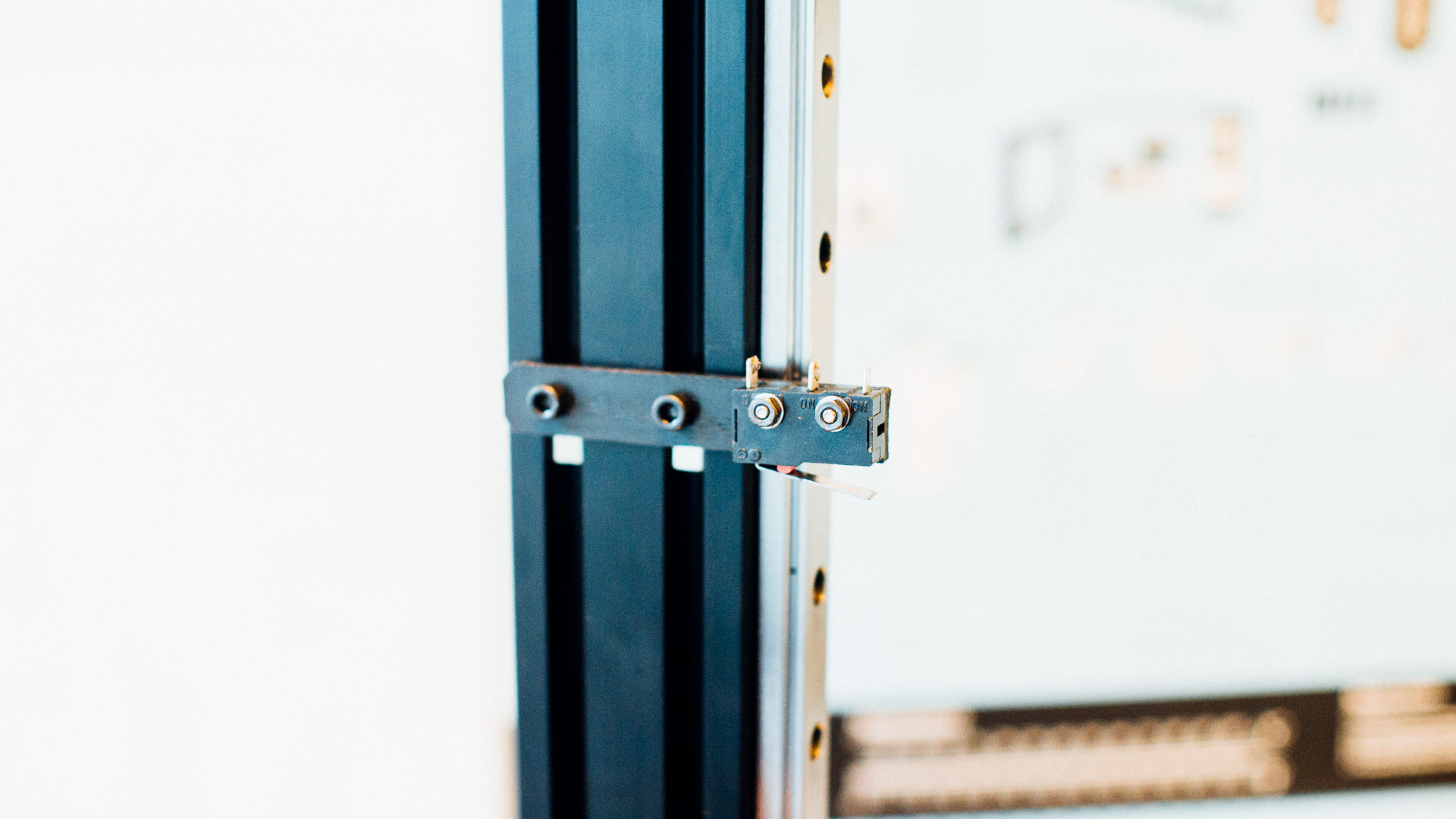
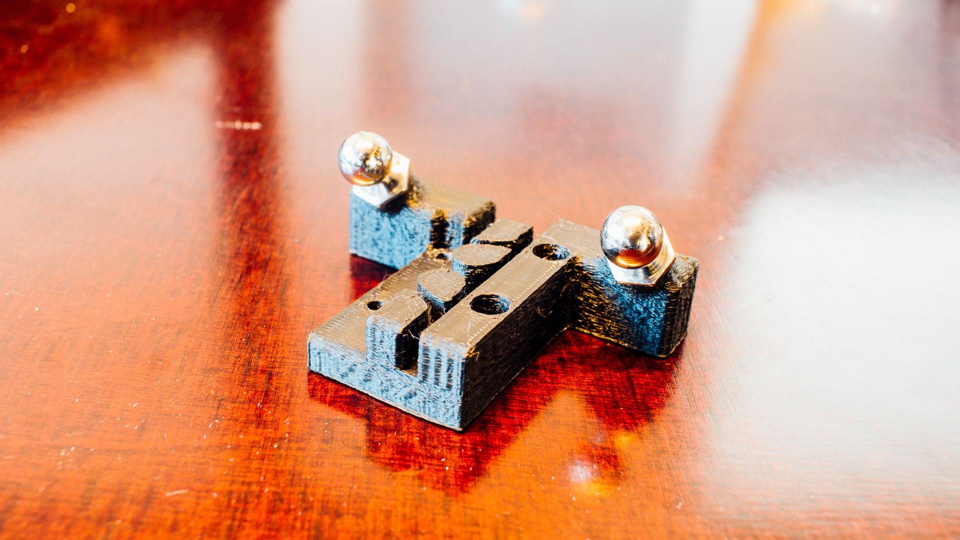
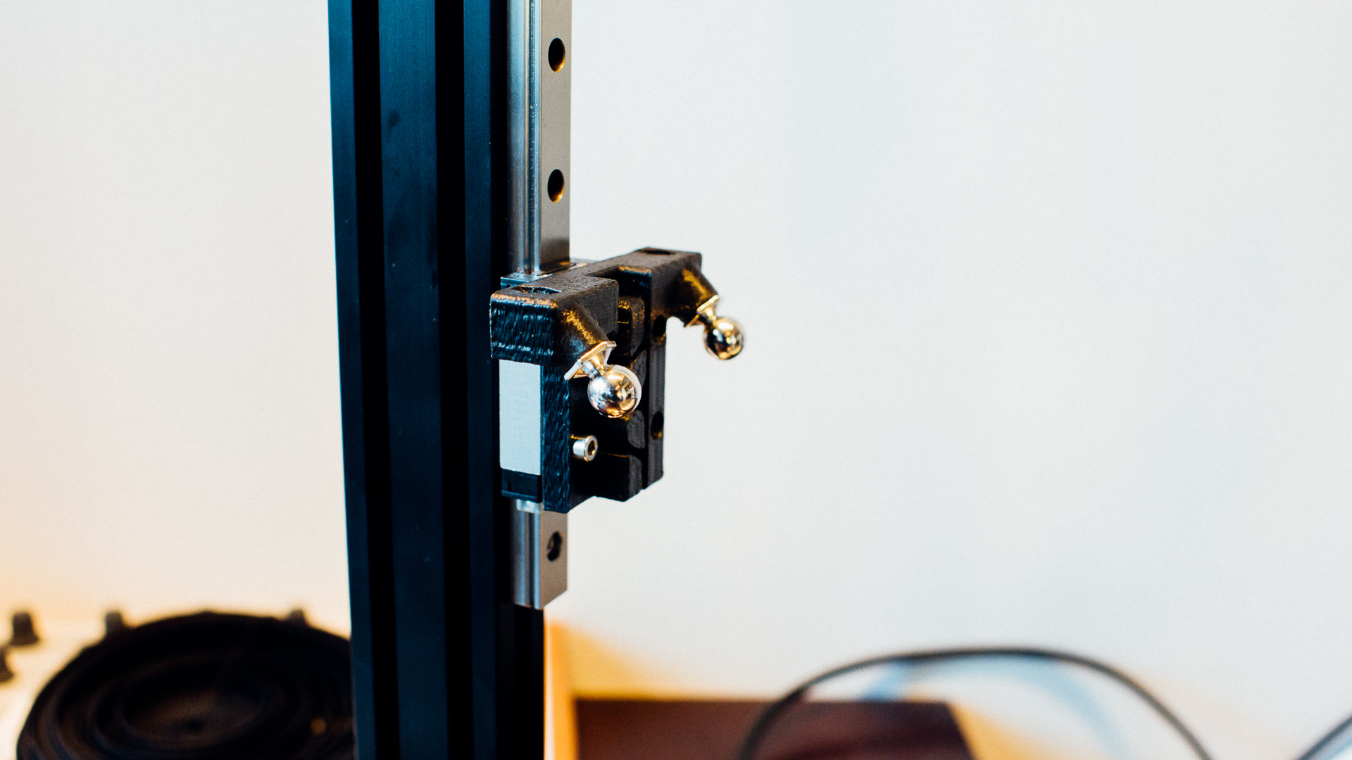
Here’s our current revision of the end-stop switch bracket at the top. This is just a very simple bracket that will keep the switch in place. The bracket position needs to be measured manually, but the relative position is not uber critical since we’ll have an IR probe near the hotend.
Idler pulleys were included with the corners from RobotDigg. These were very easy to assemble.
The Way Forward
We still have some stuff to obtain, figure out and 3D print. The effector hasn’t arrived yet and among other things we need to figure out how we want to mount the touch screen and what kind of fan we’ll use for the controller board. When we get the effector we need to make a custom bracket to the fans near the hotend and print it. We also need to solve the guide rail issue and create some custom wire panels for extrusions not unlike these.
Continue reading about this printer in part 3 where we talk about electronics and wiring!