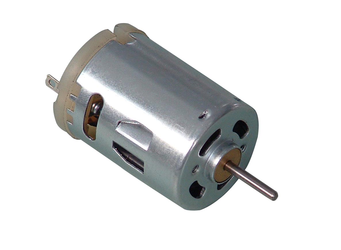
Connecting a DC motor to a power source and making it spin has to be one of the first electronics-related activity many people do in their lives. Controlling it with a microcontroller or an Arduino is not much more complicated, however it’s a couple of pitfalls you need to avoid.
Controlling the Motor and the Transistor
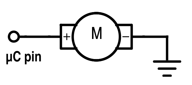
Initially one might think that connecting one motor terminal to a GPIO pin on the microcontroller and the other motor terminal to ground will suffice. This is almost always a bad idea. The reason is that the pins on a microcontroller usually struggle with delivering enough current to drive a motor like this. Some microcontrollers have smart protection systems which limits the current on a pin or shuts it off at high currents. Other microcontrollers just get fried.
Because of this you should use the microcontroller just to control the motor, not to deliver power to it. Just connect the microcontroller to the base or gate terminal (depending on the naming convention) of a transistor and let an independent power source drive the motor. Depending on the transistor you might need a relatively large resistor (typically ~10 kΩ) between the microcontroller and the transistor to limit the current flow as shown below.
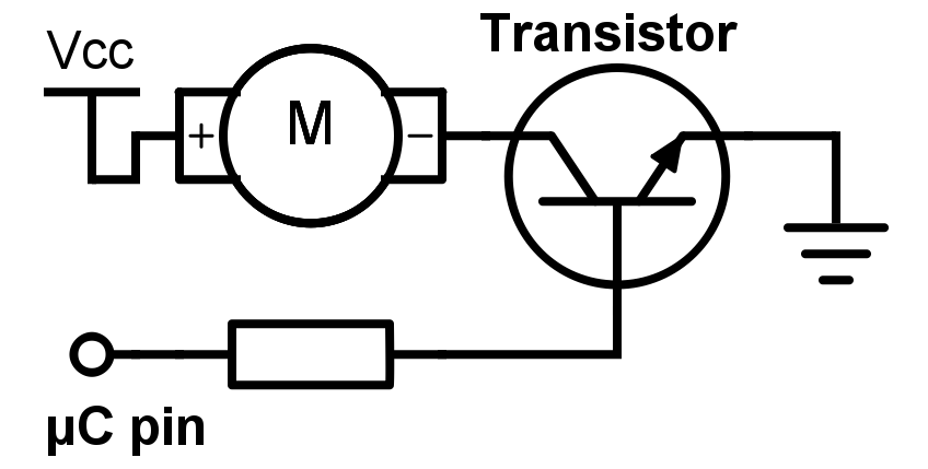
The transistor works as a switch controlled by an electric signal (in our case the signal on our microcontroller pin), in principle quite similar to a relay.
The Snubber/Flyback Diode
When the motor is going at full speed it has gained rotational inertia. So when cutting the power it doesn’t stop spinning momentarily. Instead it takes a short time for it to stop, temporarily turning the motor into a generator generating voltage. Also, a DC motor is built as an inductor, wich does what it can to resist changes in current.
So, when cutting the power, the kinetic energy in the rotor and the electrical energy stored in the inductor in the motor will both suddenly create a large amount of voltage on one of the motor terminals. The generator does its thing while the inductor raises the voltage to try to compensate for the sudden falling current. This can be dangerous to the transistor connected to the motor. The transistor doesn’t like large amounts of voltage on its collector or emitter, at least when closed.

The solution for this is to connect a snubber diode (also called a flyback diode) in parallel with the motor. A standard diode ideally makes current only flow one way. In the arrangement in the schematics above, connect it such that it permits current flow from the motor’s negative terminal to the motor’s positive terminal. By doing this, the voltage generated by the motor when cutting the power will contribute to spin itself a short while longer instead of destroying the transistor. An elegant solution!
To Summarize
- Don’t use your microcontroller to deliver power to your motor, only to control it. Use a transistor for control.
- Install a snubber diode (aka. flyback diode) to spare your transistor.