Be sure to also read the short intro post of this project here and you can watch a behind-the-scenes video here!
Sometimes, when we need to learn how to do something, we create a project out of it. This was one of those times, and what we wanted to learn was to control a bunch of individually controllable LEDs with Fadecandy and make it react to Facebook events.
The Design
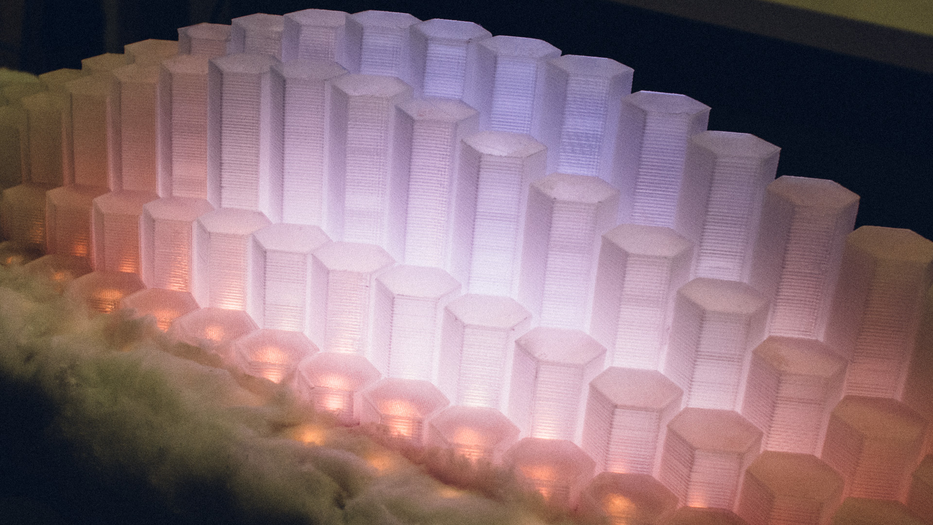
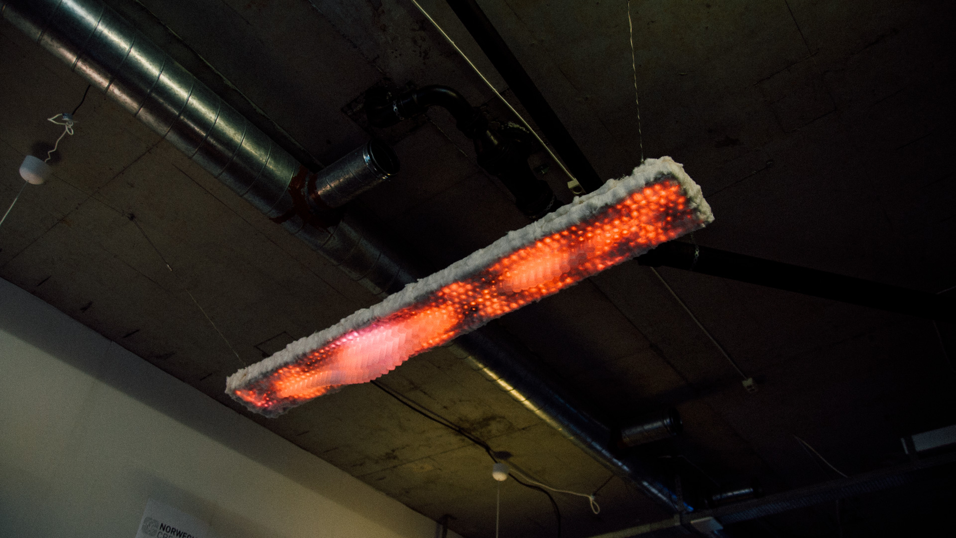
We are huge fans of parametric design, and we wanted to explore this in the project. We ended up with a large grid of 8×64 LEDs in a pattern where every LED is in the center of virtual hexagons. Above ~200 of these LEDs we would 3D-print thin, hollow and transparent hexagonal columns in different heights. The height and position of these columns would be designed parametically. Above the remaining ~312 LEDs we would glue on cotton the diffuse the light and give it a “cloud look”.
Going Parametric
Using Octave (a free alternative to MATLAB, which we grew up with on the univeristy), we created a few trigonometric functions which decided the shape of the hexagonal “mountain” across the lamp. Here’s the code:
x = linspace(1,64,64);

a1 = 0.005;
a2 = 0.007;
a3 = 0.015;
a4 = 0.07;
a5 = 0.05;
a6 = 0.05;
a7 = 0.008;
a8 = 0.001;

f1 = sin(0.1*x)+1;
f2 = cos(0.25*x)+1;
f3 = sin(0.03*x.^2)+2100;
fq = 0.001*(-(x-32).^2 + 965);

y1 = a1*(f1+f2).*f3.*fq;
y2 = a2*(2*f1+f2).*f3.*fq;
y3 = a3*(f1+2*f2).*f3.*fq;
y4 = a4*(0.5*f1+2*f2).*0.5.*f3.*fq;
y5 = a5*(1.2*f1+f2).*f3.*fq;
y6 = a6*(f1+0.1*f2).*f3.*fq;
y7 = a7*(f1+f2).*f3.*fq;
y8 = a8*(f1+f2).*f3.*fq;

A = 0.4*[y1;y2;y3;y4;y5;y6;y7;y8];
B = A - 10;

threshold = 5;
k = 0;

for i = 1:8
  for j = 1:64
    if (B(i,j) < threshold)
      B(i,j) = 0;
    else
      k = k +1;
    endif
  end
end

k
figure(1)
surf(B)
What we basically do here is creating 8 different trigonometric functions, one for each row of LEDs, creating an 8×64 matrix with values equal to the height of the hexagonal columns in milimeters. Here’s a visual representation of the matrix in Octave:
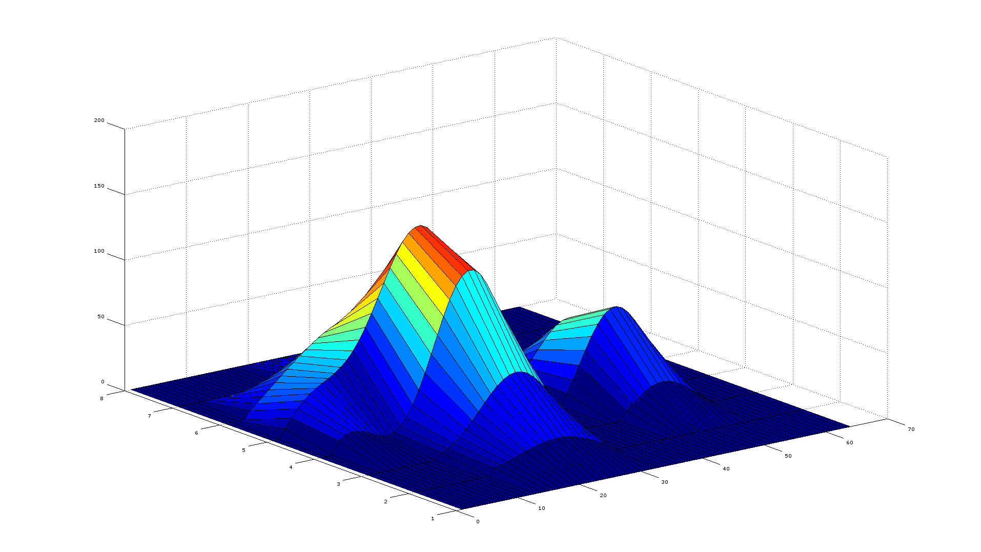
The function coefficents were found just by trial and error, using the surf() function.
CAD
As usual we wanted to make a 3D-model of the whole thing to verify the final design before starting building it.
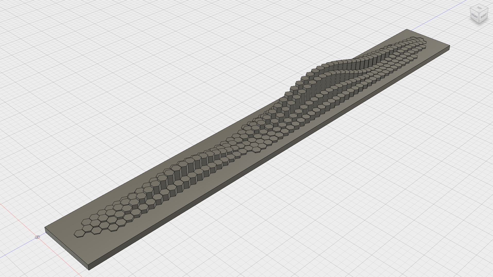
This lamp was built before we got access to a large CNC machine, which is one of the main reasons the rest of the design is rather simplistic. The screenshot is actually seen from below since the lamp would hang upside down from the ceiling with the LEDs and columns hanging below the main structure.
In addition, we modelled each column with 0.9 mm thick walls and a 0.6 mm thick “cap” for 3D-printing purposes.
Building the Lamp
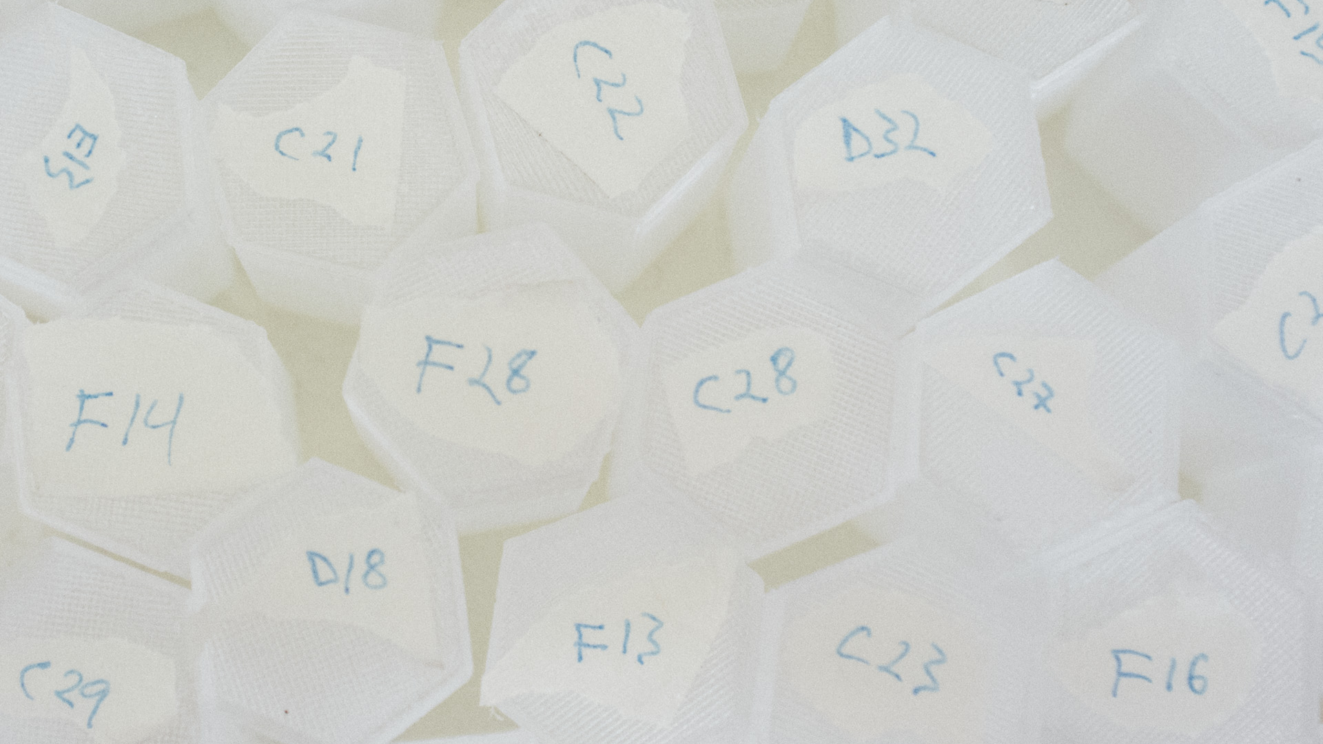
3D-Printing
We printed all the hexagonal columns individually with our good ol’ Solidoodle 3 with transparent ABS, which was quite time consuming.
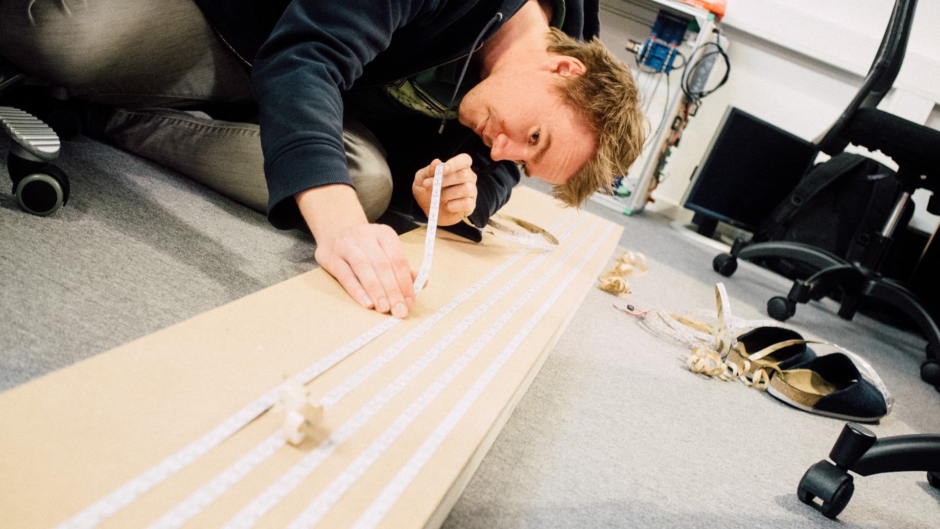
The Structure
From a sheet of MDF we cut out a piece which would serve as a mounting board for everything. To give it some thickness we attached some 2×1 in. lumber around the edge on the opposite side of the LEDs.
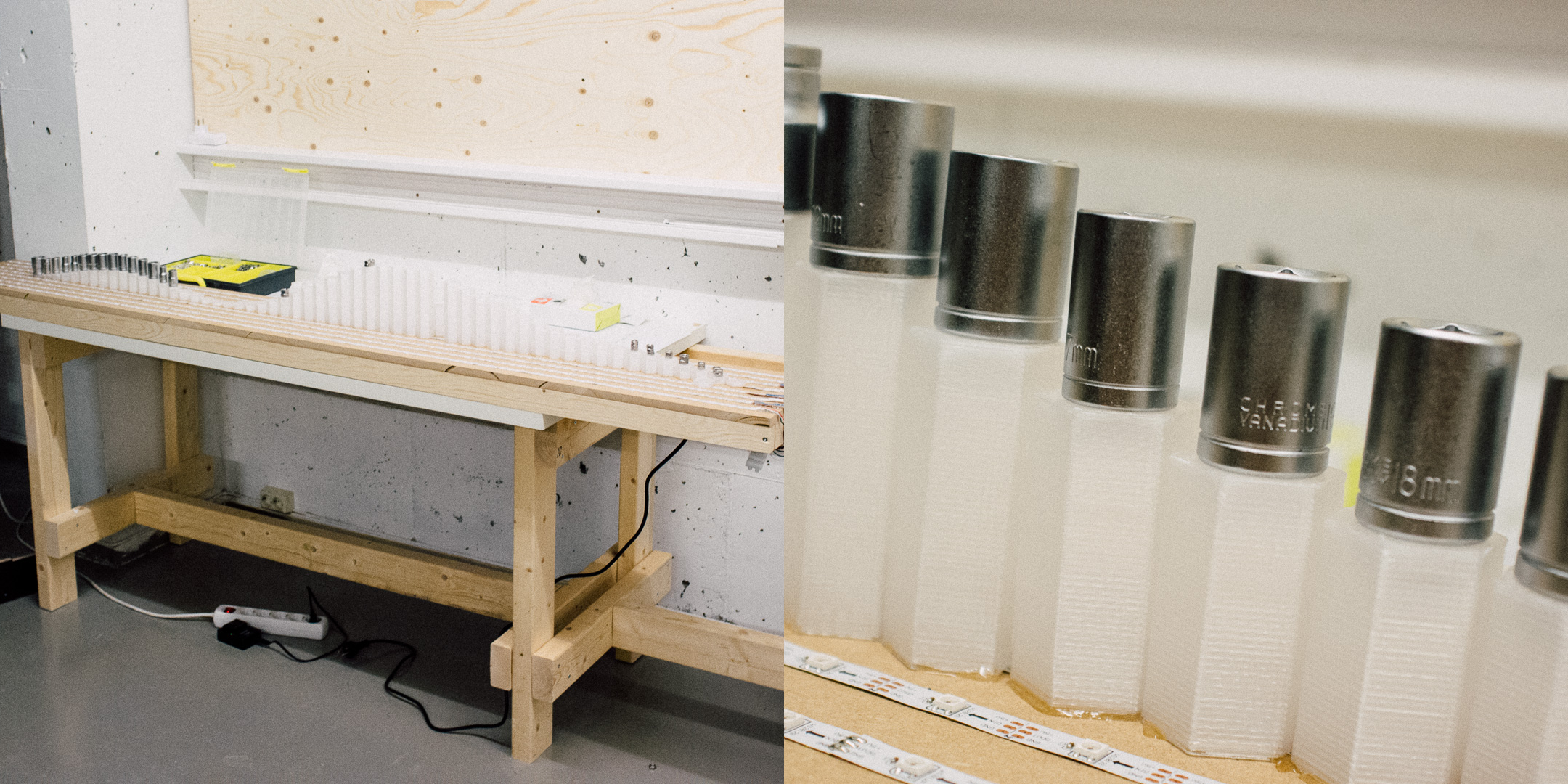
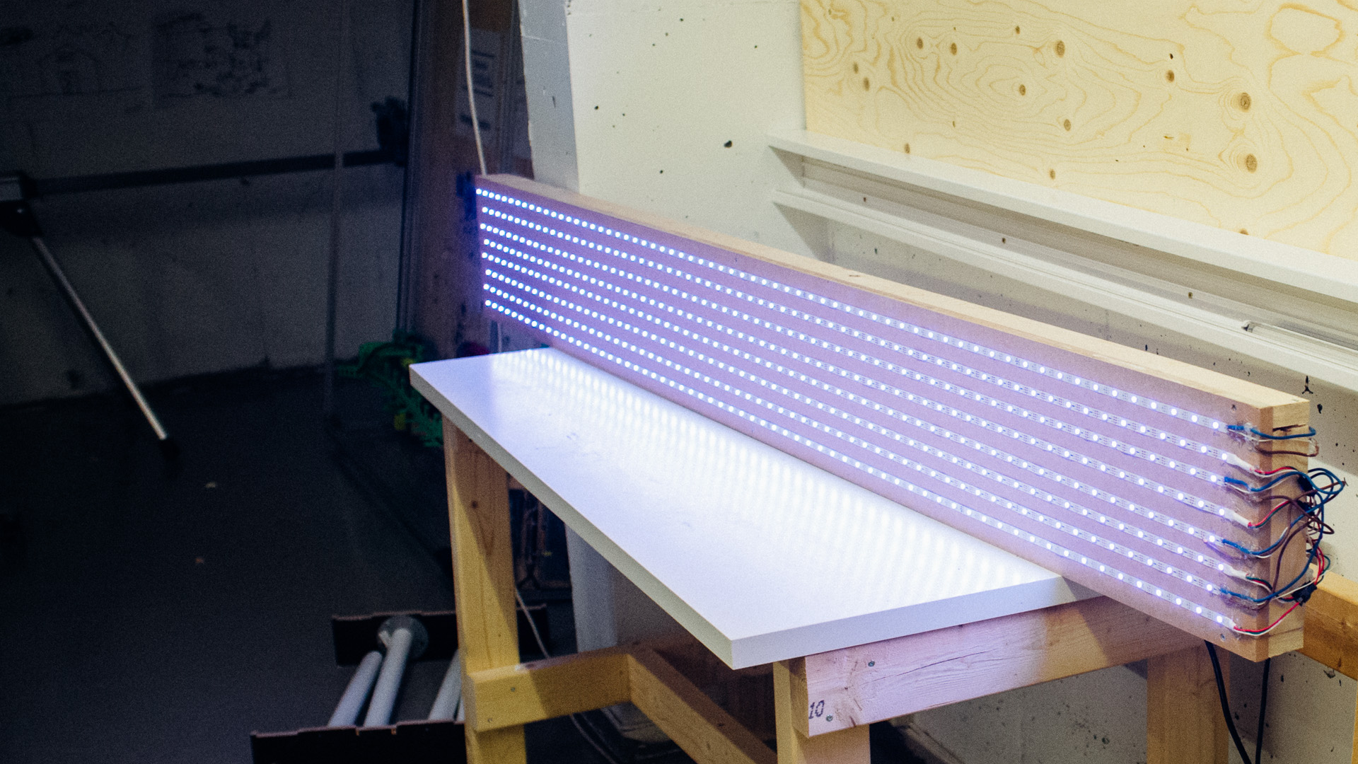
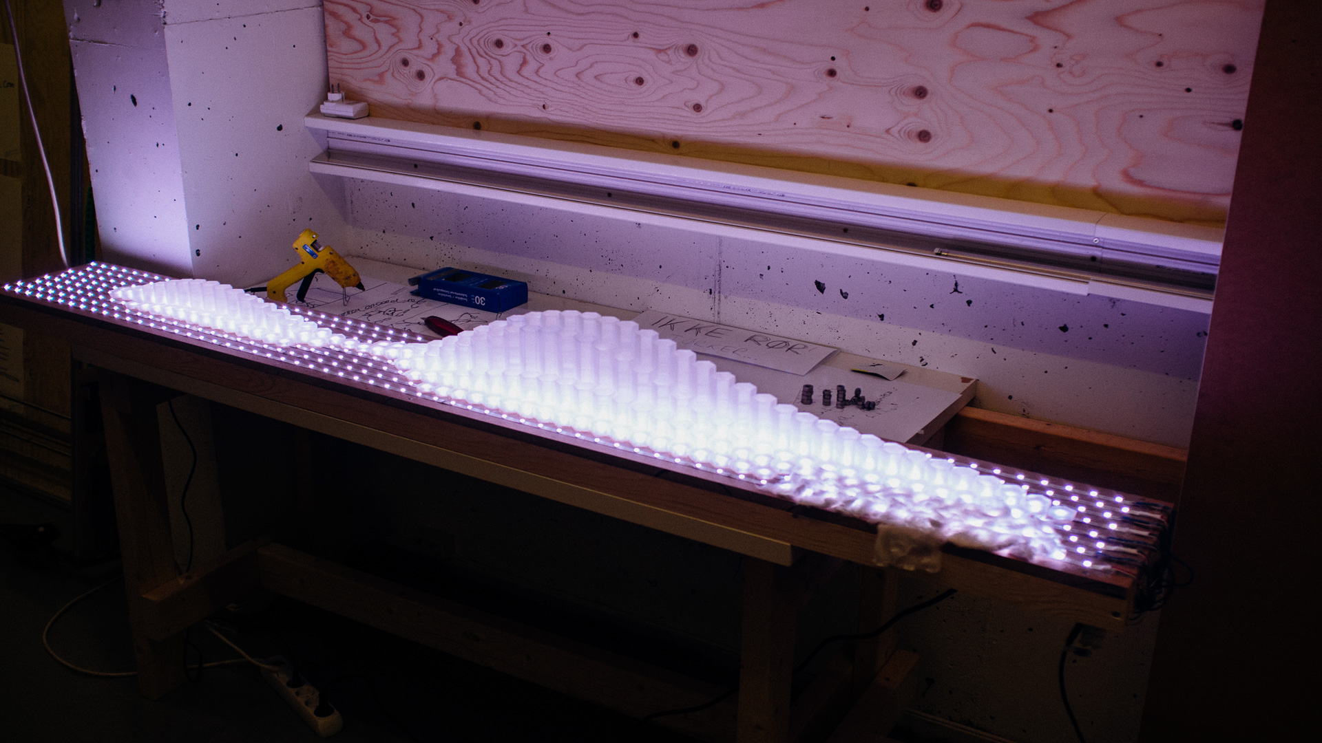
Columns, LEDs and Cotton
After the structure was done, we attached the self-adhesive LED strips on the MDF before starting gluing on all the 3D-printed columns. We then covered all of the still exposed LEDs, MDF and 2×1 in cotton.

The Hardware
LED controller
We wanted to test the “Dithering USB-controlled LED controller Fadecandy“. This board is compatible with asynchronous controlled LED strips such as these (WS2812).
In graphic intensive light installations you need good LED intensity control. So high PWM control range (12-bit+) is needed. But the WS2812 are only capable of driving the LEDs (each color) with 8-bit PWM. However, the Fadecandy board does some nice dithering on the data line making it visually comparable to LEDs controlled with much higher PWM range. You can also watch a Fadecandy dithering demo video here.
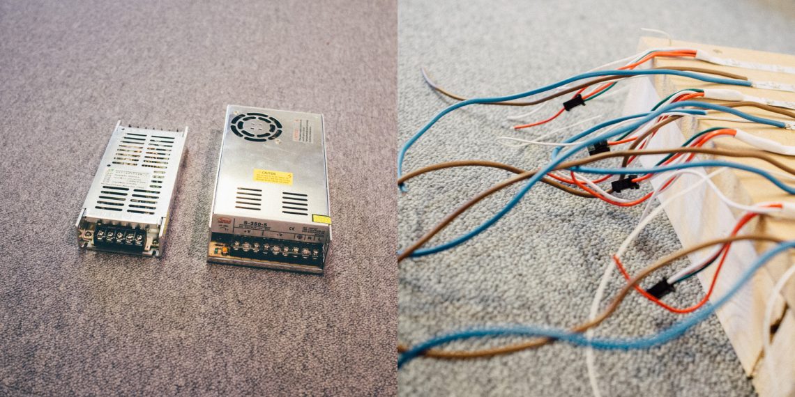
Power Supplies
In this installation you can find a 5 V 40 Amp power supply. It’s the smallest one in the image above. And it does not have a fan! Only passive cooling here.
Computer
To generate the graphics we use a Raspberry Pi B+.
The Software
A large chunk of the time making this lamp went into learning the Fadecandy framework and implementing the different parts of the software.
Mapping the LEDs
One powerful tool you should use with Fadecandy is mapping your LEDs in space, giving each LED a set of x,y,z coordinates. That way you can really unleash the power within the framework. Our LEDs exist only in the x,y plane, but we included the height of each hexagonal column as the z axis.
We wrote a simple python script which imports a .csv file created in Octave and exports a .json file which is used by the Fadecandy framework. The .csv file contains the height of each hexagonal column.
import json
import csv

leds = []
z_height = []
spacing = 33
counter = 0
i_mid = 99
j_mid = 1031

with open('lampCSV.csv', 'rb') as csvfile:
	for line in csvfile:
		str = line.rstrip('\r\n')
		l = str.split(',')
		z_height.extend(l)

for i in range(0, 8):
	for j in range(0,64):
		if i%2:
			leds.append({"point":[i*spacing-i_mid, j*spacing-j_mid, float(z_height[i+8*j])]})
		else:
			leds.append({"point":[i*spacing-i_mid, j*spacing+(spacing/2)-j_mid, float(z_height[i+8*j])]})
		counter = counter+1
leds.append({"check":counter})

with open("grid_8x64.json", "w") as outfile:
	json.dump(leds, outfile, indent=4, sort_keys=True)
outfile.close();
Creating the light programs
Using Fadecandy’s powerful framework, one can create some really complex and beautiful LED programs. We’re not going to go into detail on how we implemented the programs, but here are the basics:
We have one ambient program running when nothing happens. This program consists of two layers.
The main layer is based on perlin noise which gives it a nice organic look. It also continuously slowly fades between random hue and saturation values in the HSV weel. The noise both affects both the color and the intensity. The noise continously moves across the lamp, giving movement and life to it.
The second layer is random LEDs blinking like white stars (quick fade-in, slow fade-out) over uneven random intervals.
We are running all layers (or shaders as we should really call them) into a mixer. A third layer is running all the time as well, but is not mixed in until an event occurs (in our case when we get a new like on Norwegian Creations’ Facebook page). When the event occurs, we crossfade the ambient layers out and the event layer in, and leave it there for a short while, before crossfading it back again to where it was. The event layer is basically an intense, relatively fast up-down-fading attention-seeking program synced for all the LEDs.
Fadecandy’s framework is available in several languages, but we chose C++ as it seems to be the most powerful and versatile.
Hooking Up to Facebook
Optimally we should’ve connected to Facebook’s streaming API and received notifications from there when we got new likes, but polling a .json file each 10 seconds or so is both sufficient in our case and much easier to implement. Polling too often will eventually block the program from accessing the .json. We wrote a simple Python script which does exactly this as well as sending a message to the C++ program.
BEWARE: We have exception handling for almost each operation in this program, but have removed them to make the code a bit more compact and tidy. You will need exception handling to avoid the script to crash (the program will most likely not be able to fetch the .json every single time, for instance)!
import urllib, json, time, socket

UDP_IP = "127.0.0.1"
UDP_PORT = 12345
MESSAGE = "a"

s = socket.socket(socket.AF_INET, socket.SOCK_DGRAM)

lastLikes = 0
newLikes = 0

while True:
	f = urllib.urlopen("http://graph.facebook.com/norwegiancreations/")
	values = json.load(f)
	newLikes = values["likes"]

	if newLikes > lastLikes:
		print "NC has now %i likes on FB!" % newLikes
		s.sendto(MESSAGE, (UDP_IP,UDP_PORT))

	lastLikes = newLikes
	f.close()
	time.sleep(10)
Communicating Between Python and C++
In the above code we locally bradcast an “a” character over UDP each time we get a new like on Facebook.
In the main C++ code which run the shaders we also have an additional thread (using Pthreads) which takes care of receiving these messages and thus triggering the event. Here is the function (called “receiver”) which runs in the additional thread and receives each message:
void * receiver(void * argument)
{
    unsigned char buf[BUFSIZE];
    int recvlen = 0;

    int fd = socket(AF_INET, SOCK_DGRAM, 0);

    struct sockaddr_in myaddr;
    socklen_t addrlen = sizeof(myaddr);

    myaddr.sin_family = AF_INET;
    myaddr.sin_addr.s_addr = htonl(INADDR_ANY);
    myaddr.sin_port = htons(PORT);

    bind(fd, (struct sockaddr *)&myaddr, sizeof(myaddr));

    while(1)
    {
        recvlen = recvfrom(fd, buf, BUFSIZE, 0, (struct sockaddr *)&myaddr, &addrlen);
        if(recvlen > 0)
        {
            buf[recvlen] = 0;
            std::cout << "received: " << buf << std::endl;
            event = 1;
        }
        usleep(1000);
    }
}
It sets the global variable “event” to 1 each time it receives a message which in turn starts the crossfading between the layers.
Day/Night mode
We also have an additional tiny functionality where the lamp dims down with a factor when the time is between a set time in the evening and a set time in the morning. This far north, the sunlight during the evening/night changes dramatically between summer and winter, so optimally we should’ve used a photosensor to detect the lighting outside or in the room instead of having to manually set a time of day for the lamp to change day/night mode, but for this project this method proved sufficient.