Be sure to read part 1 where we talk about the design phase of this installation!
Mechanical and Structural
The new CNC mill in our Makerspace proved vital when building this installation. Milling the parts (they had to be milled or made by equivalent accurate methods) could of course have been done elsewhere, but at a significantly higher cost.
Since we decided to mill the parts ourselves, we had to first learn to operate the new CNC machine and CAM the jobs properly. That implied choosing the right tool for the job and material and choose a good spindle speed together with an appropriate feed rate and step-down height, among other parameters. CNC milling is a science in itself!
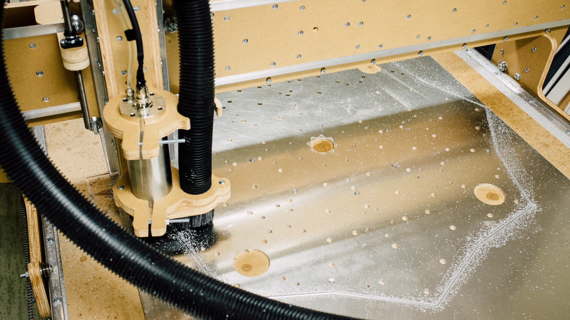
We already had some experience with milling plywood, which is relatively easy. But milling 5052 aluminium (a quite soft alloy) is a bit more tricky, especially if you have a mill like the one we are using. It is not the most rigid of mills, so we have to set up a more time-consuming toolpath to easen the load when milling these kinds of materials. At the same time we have to be careful that the aluminum don’t clog the tool during the milling.
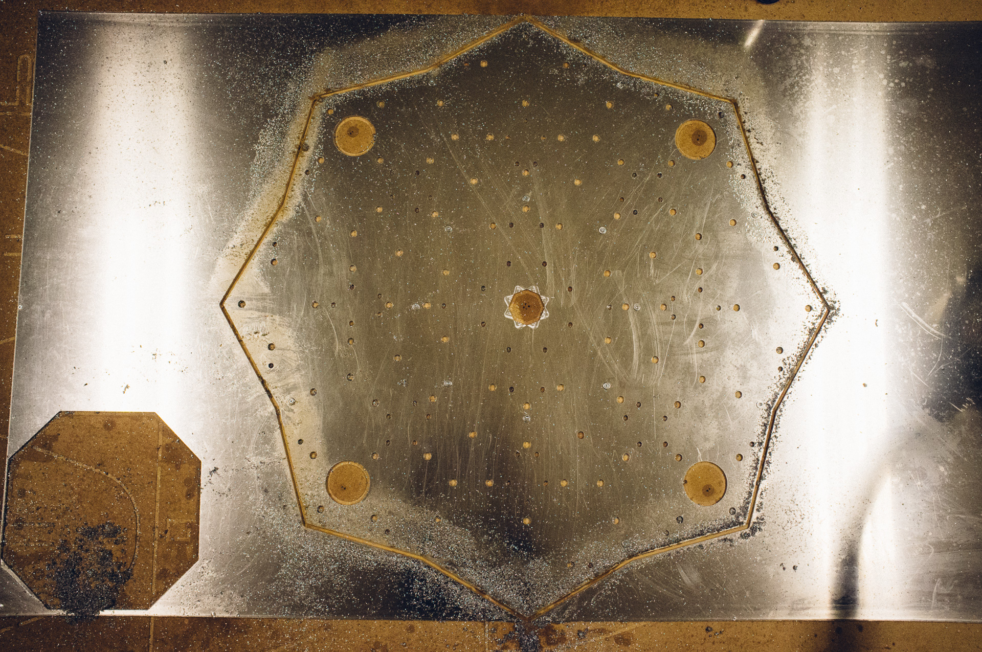
After some trial and error, we found some working parameters and we could proceed milling our aluminium pieces. Milling the perspex pieces was relatively quick and easy in comparison, and before we knew it, we had 2 pieces of aluminium as well as 24 pieces of perspex leaves fresh out of the mill.
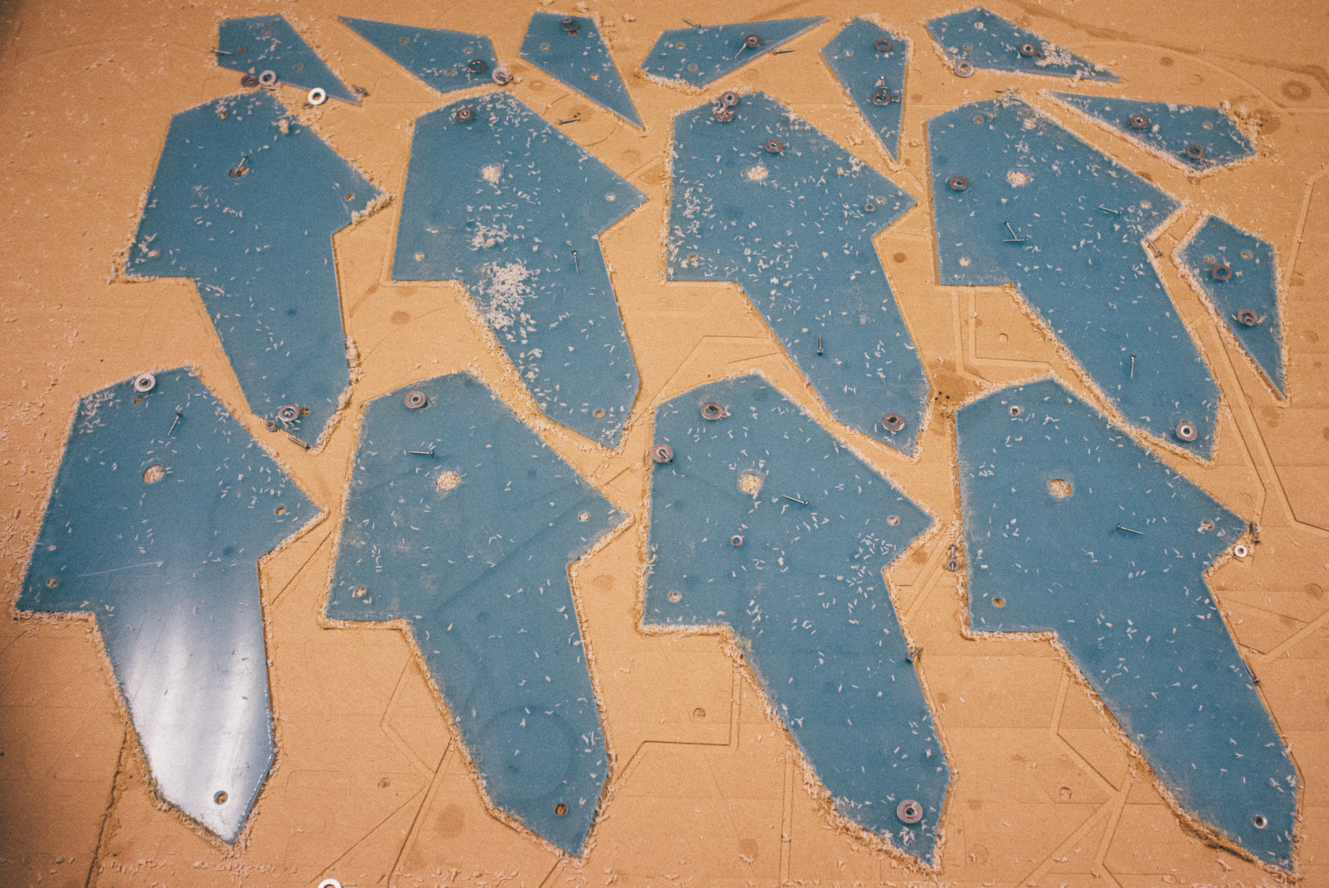
We cleaned, filed and deburred the aluminium pieces and sent it off for powder coating at a paint shop. We chose to paint it in a matte white color, and we were very satisfied with the result.
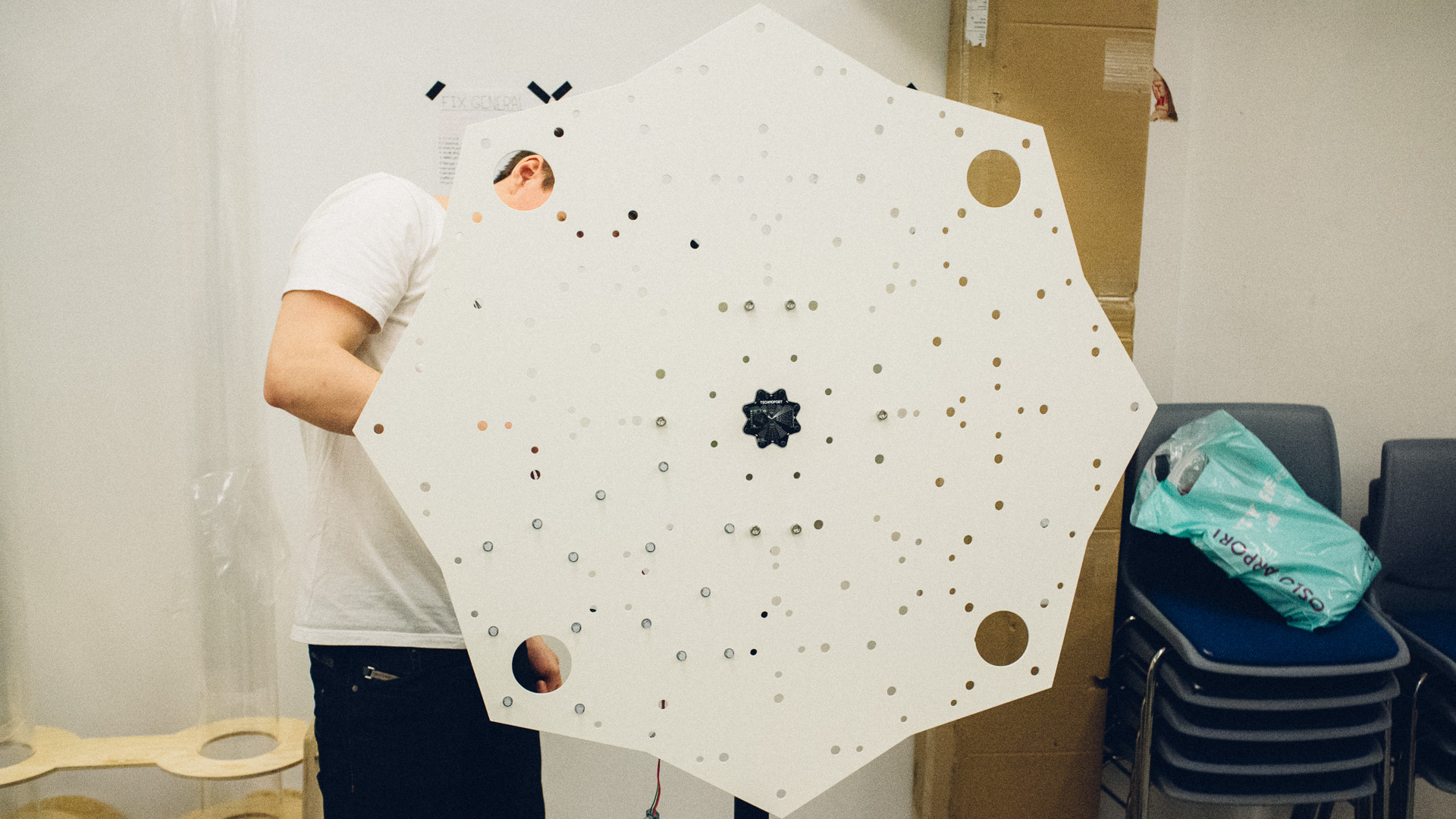
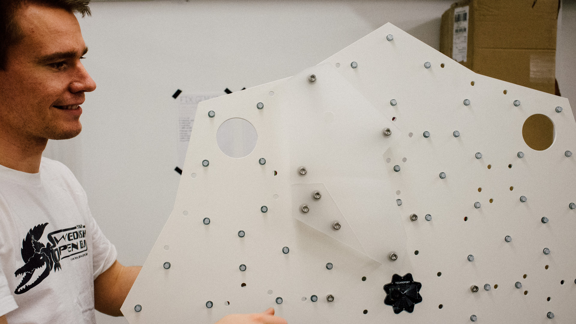
Once we got it back, we mounted the aluminium plates together using the large steel spacers from China (these are described in more detail in pt. 1) before setting it up on the stand, mounting the LEDs and the perspex leaves.
We didn’t have very small endmills for the CNC at the time, so mounting holes for the center PCB and the speakers had to be drilled manually.
Software and Electrical
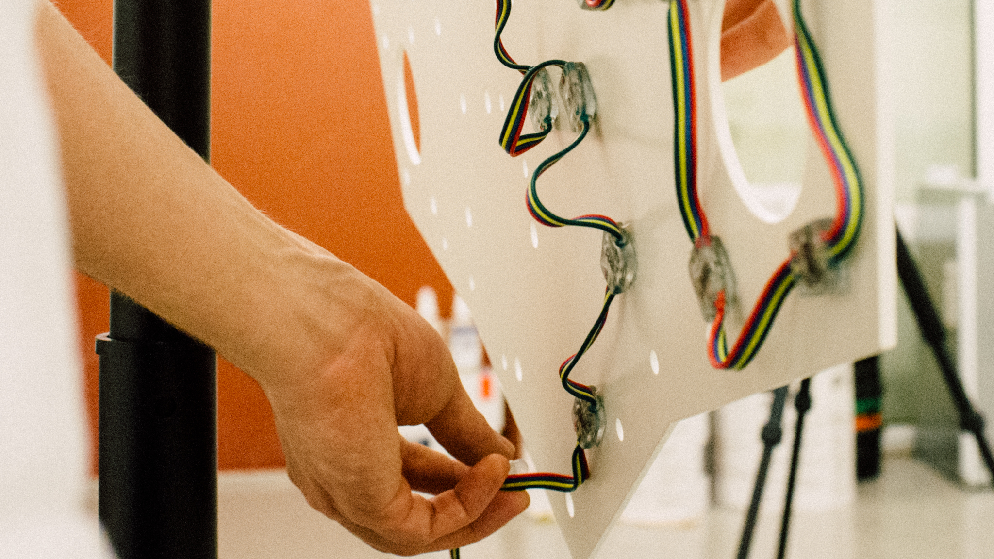
The amplifier needs 12V while the rest needs 5V, so we decided to use two seperate power supply units. The LED wires worked as a handy way to fetch 5V different places on the back of the aluminium plate.
The Raspberry Pi
As mentioned in part 1, the Raspberry Pi controls the time-lapse camera and ideally the music and sound. Everything is coded Python and for the camera we use the picamera module. It’s very easy to set up and use as seen below.
import picamera, time

photo_frequency_seconds = 30;

camera = picamera.PiCamera()

camera.rotation = 270
camera.resolution = (1280,720)

seconds = 0
last_time = time.strftime("%Y%m%d%H%M%s")

while True:
    if last_time != time.strftime("%Y%m%d%H%M%s"):
        last_time = time.strftime("%Y%m%d%H%M%s")
        seconds += 1

    if seconds >= photo_frequency_seconds:
        try:
            camera.capture(last_time + ".jpg")
        except IOError:
            print ("I/O error! (Disk full?)")

        seconds = 0

    time.sleep(0.1)
In this case we are taking 720p images every 30 seconds and naming the files their timestamp (YearMonthDayHourMinuteSecond.jpg). Picamera also has an own timelapse module, but we didn’t utilize that.
For the sound triggering, we coded sampler script i Python using a module called Pygame. This way we could have an ambient soundscape running in the background and at the same time trigger other sounds on top of it when receiving messages over USB serial from the Arduino. Here’s the code with quite a few lines omitted due to repetitiveness (only two triggered sounds instead of eight):
import pygame, os, serial, time

tex_length = 120
fade_length = 5
num_channels = 34;

last_played_1 = 1
last_played_2 = 1

os.system("amixer cset numid=1 -- 400")

ser = serial.Serial('/dev/ttyACM0',115200, timeout=0.001)

pygame.mixer.pre_init(22050, -16, 2, 10000)
pygame.init()

pygame.mixer.set_num_channels(num_channels)

texture = pygame.mixer.Sound('Texture1.ogg')
tone1 = pygame.mixer.Sound('Tone1.ogg')
tone2 = pygame.mixer.Sound('Tone2.ogg')

texChannel_1 = pygame.mixer.Channel(0)
texChannel_2 = pygame.mixer.Channel(1)

t11Channel = pygame.mixer.Channel(2)
t12Channel = pygame.mixer.Channel(3)
t13Channel = pygame.mixer.Channel(4)
t14Channel = pygame.mixer.Channel(5)

t21Channel = pygame.mixer.Channel(6)
t22Channel = pygame.mixer.Channel(7)
t23Channel = pygame.mixer.Channel(8)
t24Channel = pygame.mixer.Channel(9)

texChannel_1.play(texture)
start = time.time()

x = 0;

while True:
    x = ser.read()
    if x == '1':
        if last_played_1 == 1:
            t12Channel.play(tone1)
            last_played_1 = 2
        elif last_played_1 == 2:
            t13Channel.play(tone1)
            last_played_1 = 3
        elif last_played_1 == 3:
            t14Channel.play(tone1)
            last_played_1 = 4
        else:
            t11Channel.play(tone1)
            last_played_1 = 1
    elif x == '2':
        if last_played_2 == 1:
            t22Channel.play(tone2)
            last_played_2 = 2
        elif last_played_2 == 2:
            t23Channel.play(tone2)
            last_played_2 = 3
        elif last_played_2 == 3:
            t24Channel.play(tone2)
            last_played_2 = 4
        else:
            t21Channel.play(tone2)
            last_played_2 = 1
    else:
        pass

    if time.time() >= (start+tex_length-fade_length) and texChannel_1.get_busy() == True:
        texChannel_1.fadeout(fade_length*1000)
        texChannel_2.play(texture,fade_ms=(fade_length*1000))
        start = time.time()
    elif time.time() >= (start+tex_length-fade_length) and texChannel_2.get_busy() == True:
        texChannel_2.fadeout(fade_length*1000)
        texChannel_1.play(texture,fade_ms=(fade_length*1000))
        start = time.time()
    else:
        pass
To avoid abrupt ends (and thus a clicking noise) on a triggered sample, we run kind of a round robin style system where each tone has four dedicated channels each which are used in rotation. The soundscape/texture crossfades with a new instance of itself on a different channel everytime it approaches the end of the sound.
These two scripts are starting automatically when we plug the installation in the power socket. If we want to keep the Raspberry Pi off and still have the lights on, we have the ability to disconnect it from the 5V net via an easily accessible connector.
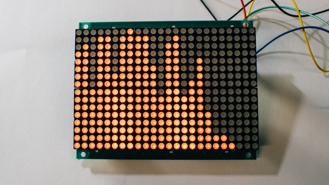
The Arduino and the LEDs
This installation contains a total of 92 12 mm diffused RGB leds with individual WS2801 controllers. The LEDs need up to 60 mA at 5V each, so we needed a power supply able to deliver at least (92 * 60 mA) * 5 V = 27.6 W. This power supply was also going to supply the Raspberry Pi and the Arduino so it had to be able to supply a bit more. We installed a 5V PSU with tha ability to deliver 50W (10A). You should always upscale your PSU!
The LEDs are controlled by the Arduino. The Raspberry Pi can stream frames over USB, but the Arduino is able to generate graphics as well when the Pi has to do other things.
And in the video you can see a HSV-wheel that slowly turns around. This graphic is generated on the Arduino.
The LEDs is easy to control and Adafruit has created an Arduino library for that (available here).
And it’s rather easy to calculate the HSV color values based on hue, saturation and value. Elco Jacobs has published a function for that here.
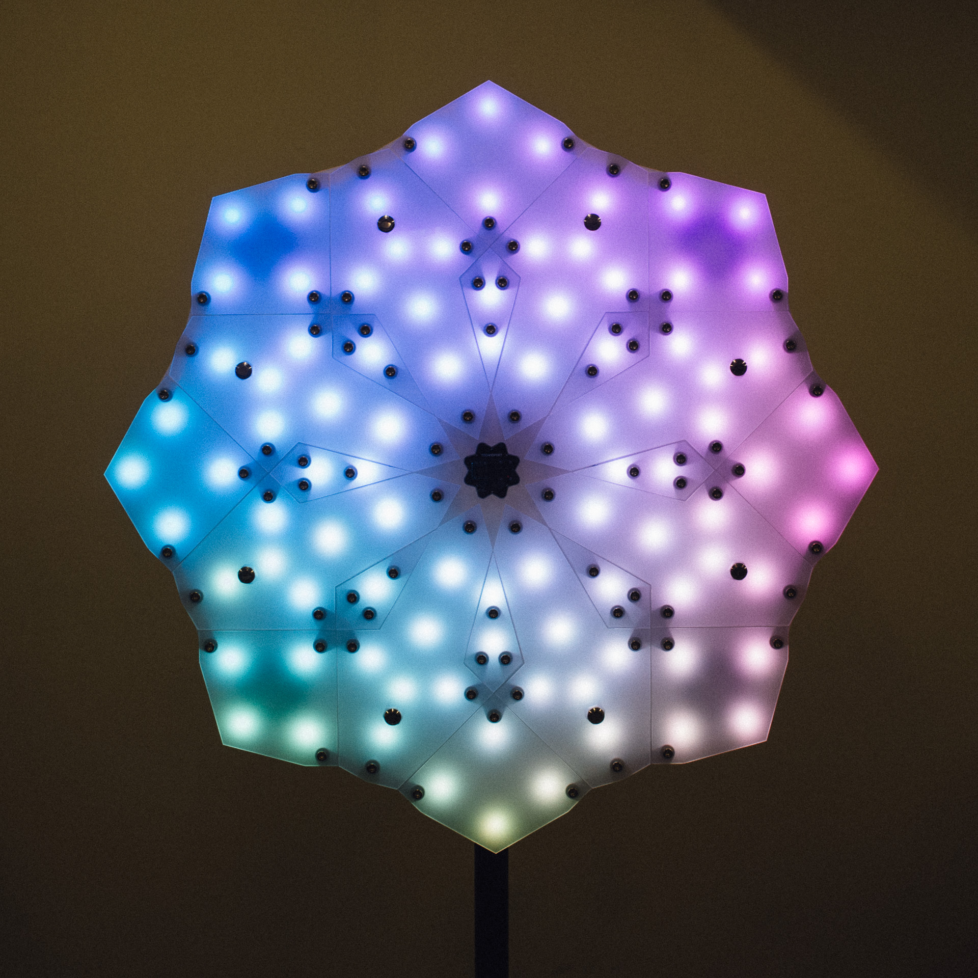
Mapping the leds in this case is the process relating the physical led position to the actual led number (as seen from the hardware and software). We mapped distance from the middle and angle (polar coordinates). This mapping resulted in two arrays: uint16_t LED_DEG[] with the led angles and uint8_t LED_RAD[] with led distance from the centre (rounded to closest mm and degree).
So what did we want to do?
We wanted to give each LED a color from the HSV color wheel based on its position. This static image was rather easy to create given our polar mapping:
for(uint8_t i = 0; i<NR_LEDS; i++){
    hsv2rgb(LED_DEG[i],LED_RAD[i], 255, &red, &green, &blue, 255);
    strip.setPixelColor(i,Color(red,green,blue));
}
This creates a smooth static image as shown in the picture below. But to make it more dynamic we rotated it around the centre. To do that the only variable we needed to change periodically was LED_RAD[].
And because of fixed point arithmetic we had some challenges around 0 degrees. Rounding errors caused occasionally some discontinuous “cracks” in the wheel. To conceal these ugly artifacts we created a really quick-and-dirty low-pass filter which ensured that every LED never changed color faster than a given factor. This smoothed out the graphics, but of coursed: used more resources!
To summarize with code, generating this pattern can be done like this (after initializing the HW):
void loop() {
  uint16_t DEG = 0;
  unsigned char red, green, blue;

  if(LEDS_ON_TARGET){
    for(uint8_t i = 0; i<NR_LEDS_; i++){
      DEG = LED_DEG[i] + DEG_MODIFIER;
      if(DEG>360) DEG -= 360;

      // generate "wish" colors
      hsv2rgb(DEG,LED_RAD[i], 255, &red, &green, &blue, 255);

      LED_COLORS_WISH_R[i] = red;
      LED_COLORS_WISH_G[i] = green;
      LED_COLORS_WISH_B[i] = blue;
    }
    DEG_MODIFIER++;
  }

  // compare all "wish" colors with actual colors
  for(uint8_t u = 0; u<NR_LEDS_; u++){
    if(LED_COLORS_WISH_R[u] > LED_COLORS_R[u]){
      LED_COLORS_R[u]++;
      LEDS_ON_TARGET = false;
    }
    else if(LED_COLORS_WISH_R[u] < LED_COLORS_R[u]){
      LED_COLORS_R[u]--;
      LEDS_ON_TARGET = false;
    }else{
      LEDS_ON_TARGET = true;
    }

    if(LED_COLORS_WISH_G[u] > LED_COLORS_G[u]){
      LED_COLORS_G[u]++;
      LEDS_ON_TARGET = false;
    }
    else if(LED_COLORS_WISH_G[u] < LED_COLORS_G[u]){
      LED_COLORS_G[u]--;
      LEDS_ON_TARGET = false;
    }else{
      LEDS_ON_TARGET = true;
    }

    if(LED_COLORS_WISH_B[u] > LED_COLORS_B[u]){
      LED_COLORS_B[u]++;
      LEDS_ON_TARGET = false;
    }
    else if(LED_COLORS_WISH_B[u] < LED_COLORS_B[u]){
      LED_COLORS_B[u]--;
      LEDS_ON_TARGET = false;
    }else{
      LEDS_ON_TARGET = true;
    }
  }

  for(uint8_t o = 0; o<NR_LEDS_; o++){
    strip.setPixelColor(o,Color(LED_COLORS_R[o],LED_COLORS_G[o],LED_COLORS_B[o]));
  }
  strip.show();

  if(DEG_MODIFIER >= 360) DEG_MODIFIER = 0;

  // INSERT SLEEP OR BUSY WAIT TO NEXT FRAME HERE!
}
This created a smooth turning HSV-wheel.
A Few Final Words
This was a very rewarding project to work with. We learned a lot along the way and we were very happy with the result. This project stands out from what we usually do since the focus was just as much on the aesthetics as the functionality and the HW/SW. However, we would really like to work with similar types of projects in the future!
Stay tuned for more from Technoport 2015 next week!