For Technoport 2015 we were tasked to create an installation which would be displayed in the lobby at the event. Its main task would be to work as a gathering point and an ice-breaker for the attendees. We wanted it to look very good and at the same time have some technical features. With no specific requirements from Technoport themselves, it was mainly up to us to come up with something cool (and that’s how we really like it) 🙂
You can read about the finished project (and watch an awesome behind-the-scenes-movie) here.
The Mechanical and Physical design
We thought it would be nice if this installation resembled the technoport logo shown below.
This is a very cool logo to use as a design base for the installation. It is compiled of eight hexagons, arranged in an eight-way radially symmetric manner, and these hexagons overlap in both two and three layers.
We wanted LEDs to light up the installation through a layer of material on the front of the installation. This layer would have the pattern of the logo and form the “facade” of the installation. To layer the front as it is layered in the logo would be unnecessary complex, so we decided to flatten everything into one single plane. This facade layer would consist of 3 different types of pieces with 8 pieces per type, adding up to 24 pieces in total. These front pieces were quickly named “leaves”, as the whole logo kinda looks like a flower. With a small space between the leaves, one can clearly see the shape of the logo, even though none of the leaves are hexagons themselves.
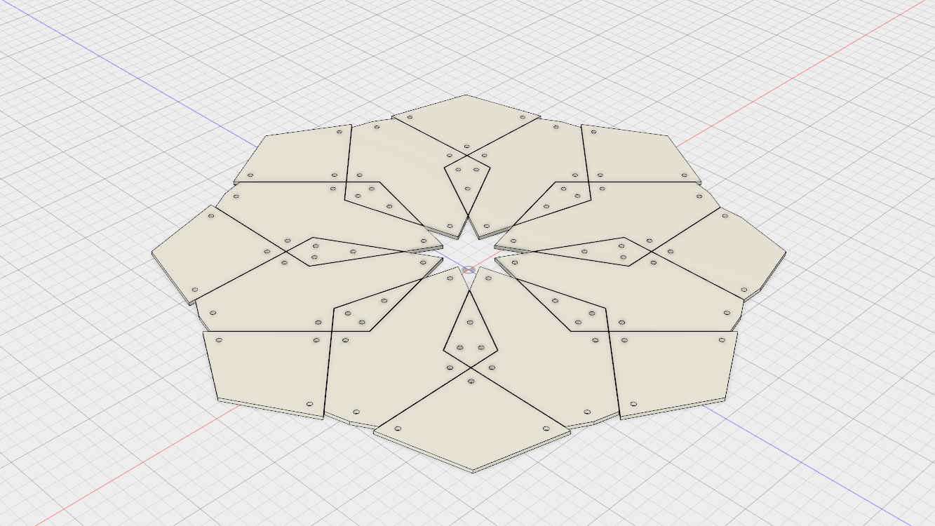
After looking at several types of materials for the leaves, we landed on using 5mm thick semi-opaque perspex plates. This material softened up the LEDs with just the right amount and ensured a soft, but still vibrant look in the end.
The facade layer would just be there for the looks and have no other functionality (except to be a mounting plate for the buttons, which will be discussed later). We needed something more rigid to hold everything in place and work as the main structure for the whole installation. For this purpose we decided to use a 4 mm aluminium plate, mounted 40 mm behind the leaves which later would be powder coated with a matte white paint. The shape of this main structure layer would be the same as the outline of the whole logo (and thus also the outline of the facade layer).
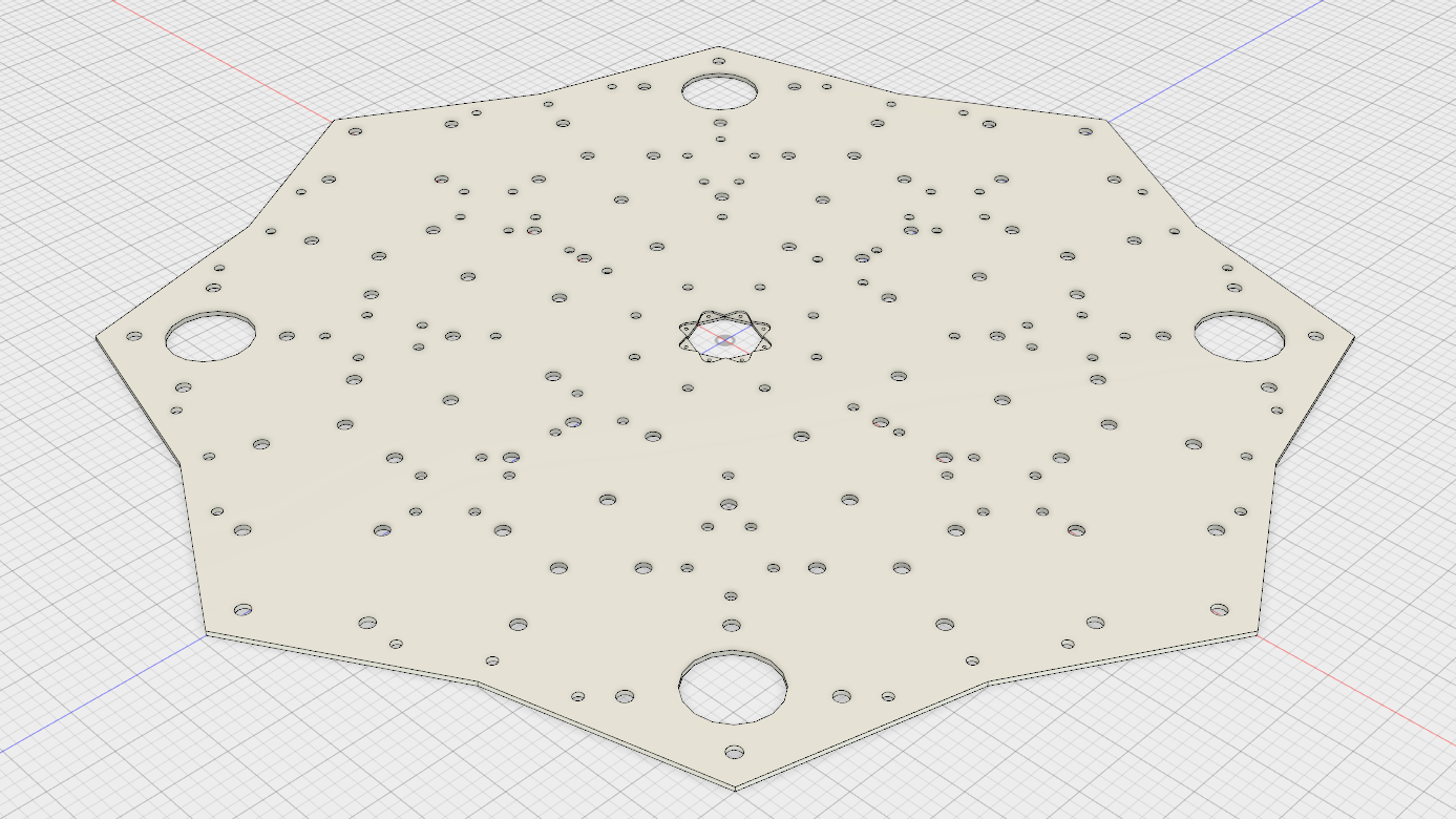
As one can see on the CAD screenshot from above there are some extra large holes present as well as a slot in the center. The extra large holes are for sound speakers and the slot in the center is for a custom designed PCB. These things are discussed later in this post. The smallest holes are for fastening bolts and the slightly larger ones are for the LEDs.
To fasten the leaves to the aluminium plate we used 80 M8 bolts and the same amount of (somewhat over-dimensioned) 40 mm steel spacers (20mm outer Ø) custom built in China. In retrospect, we could have used both thinner bolts and spacers.
Of course we needed a way to mount the installation as well, and the way we ensured that this was possible was to mount a smaller aluminium plate behind the previously mentioned one. This plate forms the far rear of the installation and its only purpose is to be something one can mount a large VESA mount onto. It is fastened to the larger aluminium plate with the same type of bolts and spacers as between the two front layers.
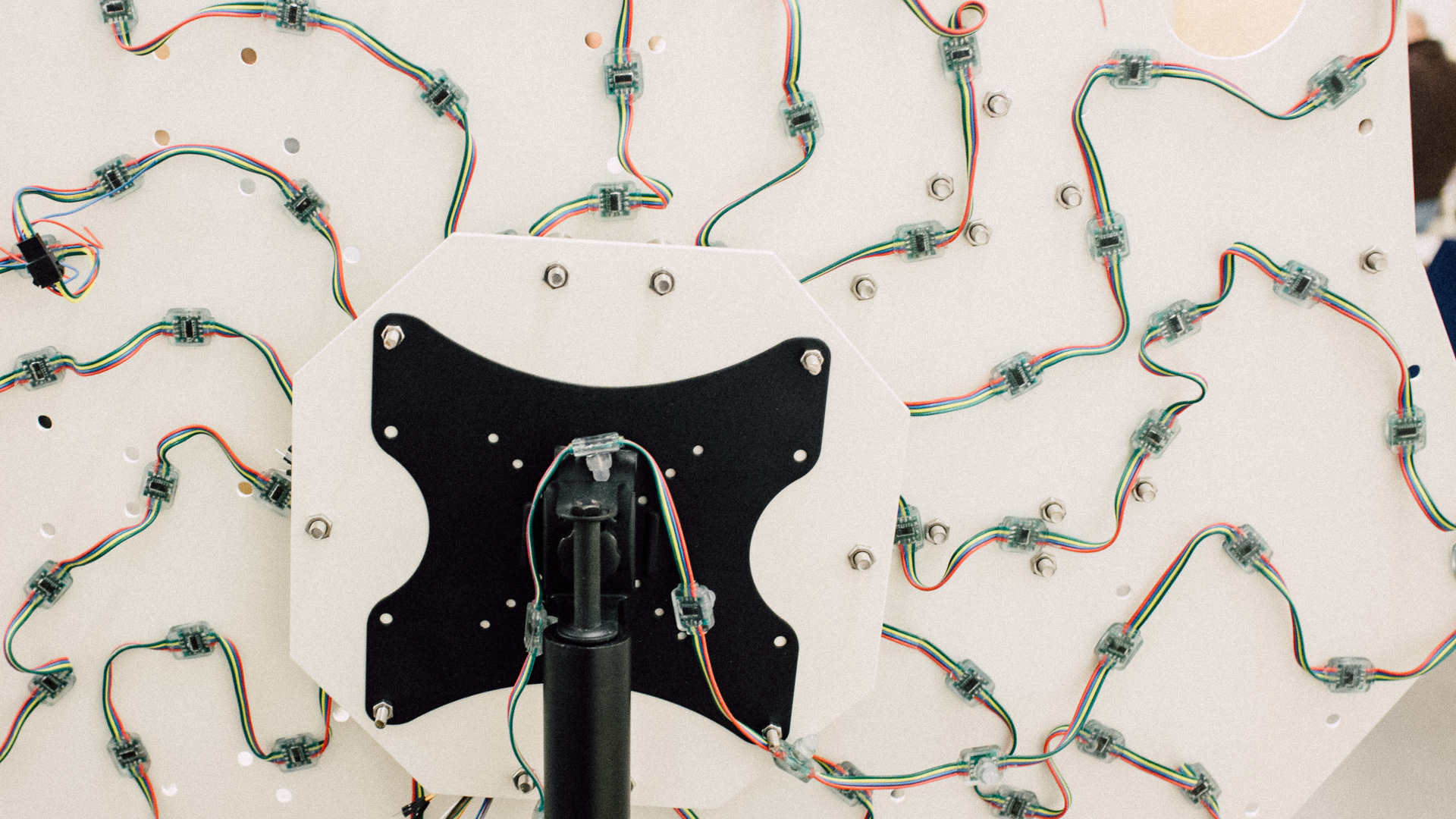
We acquired a VESA stand for the installation to be mounted on (it is actually a ceiling rack, but it does the trick). On the bottom we put toghether a rough foot with 2×4″ lumber which later would be covered up by a blanket for aesthetic reasons.
The Electrical and Functional Design
The installation ended up having the following features:
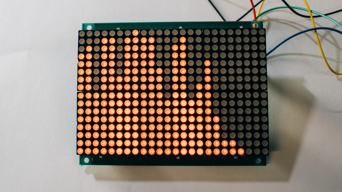
- 92 individually controllable RGB LEDs
- A Raspberry Pi attached to a Raspberry Pi Camera Board taking time-lapse photos of whatever is in front of the installation
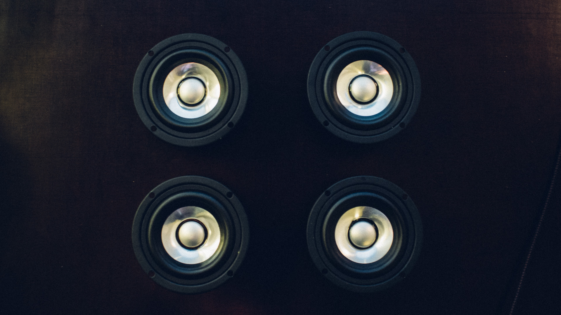
- 4 speakers playing back a looped soundscape
- An ultrasonic distance measurement sensor
- 8 easily mappable (e.g. for light and/or sound triggering) push buttons on the front
Hardware used:
- Raspberry Pi Model B+ and a Raspberry Pi Camera Board
- Arduino Leonardo
- Adafruit 20W Stereo Audio Amplifier – MAX9744
- 4 Fountek FE83 speakers
The Raspberry Pi (ideally) handles the camera as well as the music and sound played through the speakers. One issue we had was that the Raspberry Pi couldn’t take photos without making the sound stutter. It seemed like the photo capture process hogged all the CPU resources even with a low task priority. Using the newest Rasperry Pi model would perhaps have solved the issue. We didn’t have one, so the way we solved the issue temporarily was to use an iPod Shuffle to play the sound instead.
The Arduino controls the LEDs and handles any input from the buttons and the ultrasonic sensor. If the buttons need to trigger any sound (if we have the Rasperry Pi running the sound), the Arduino sends a message over USB serial to the Raspberry Pi. To minimize the CPU load on the Arduino, we are running a simple, yet effective and beautiful, LED program which basically is a rotating HSV wheel at max value.
The amplifier has a 3.5 mm stereo mini-jack input interface which is directly connected to the Raspberry Pi (or the iPod). We soldered on a potentiometer to easily be able to adjust the sound volume. Since the output impedance of the amp is 4 ohms and the speaker impedance is 8 ohms, connecting the two right channel speakers in paralell and the two left channel speakers in paralell is a perfect solution, as explained here.
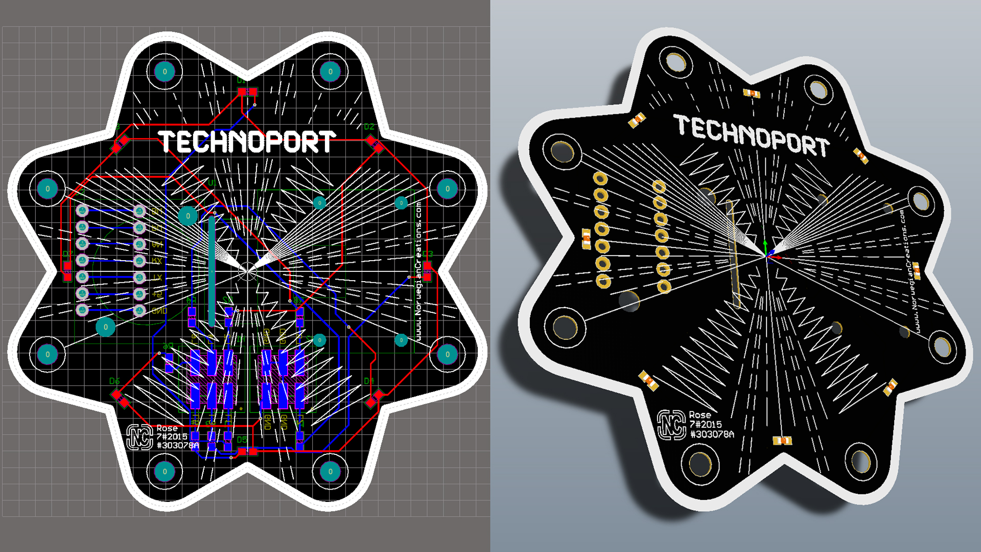
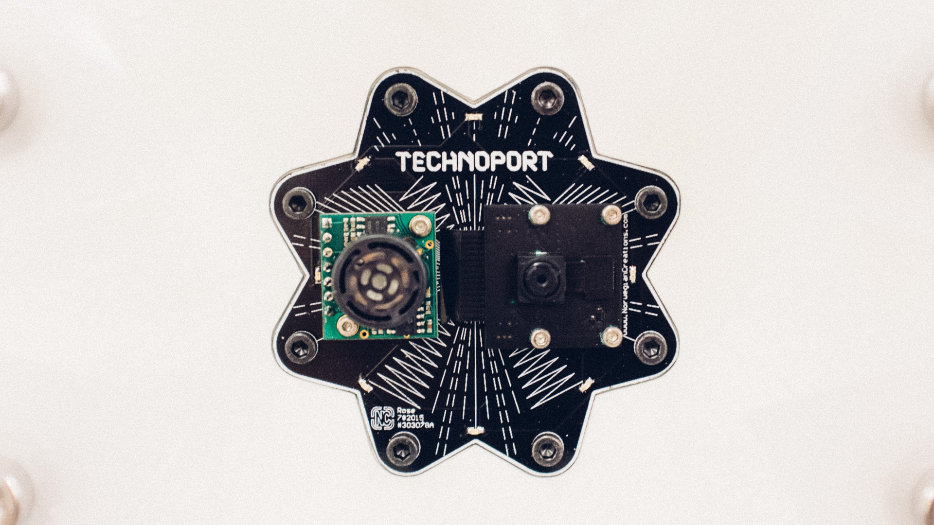
In the center of the installation we have mounted a custom designed PCB. This PCB has two purposes: to be a mounting platform for the camera and the ultrasonic sensor, and to look awesome!
In the next post we will dig deeper into the building process of this installation!