As stated in the Overview post, we wanted to base our core design on the previously built Laser Engraver. That implies using the same basic frame principle as well as stepper motors for actuating the machine in the XY plane using belts and cogs, steel rods and linear bearings.
The Core XY design principle we initially had in mind turned out to be unnecessarily complicated to implement, and our experiences with the basic Laser Engraver design turned out to be invaluable.
The Parts
The Frame
The familiar 20x20mm aluminium profiles from Misumi forms the main frame. Corner brackets curtomized for these profiles are used to hold it all in place. On the back we have mounted two wooden plates. Optimally, we would’ve chosen one single plate to cover the whole back, but our local wood dealer was not able to deliver large enough plates.
Since we wanted to minimize the z-height of the frame (for practical reasons), we chose to have only two profiles on top of eachother instead of three. This resulted in the frame being a bit more wobbly during transportation than desired.
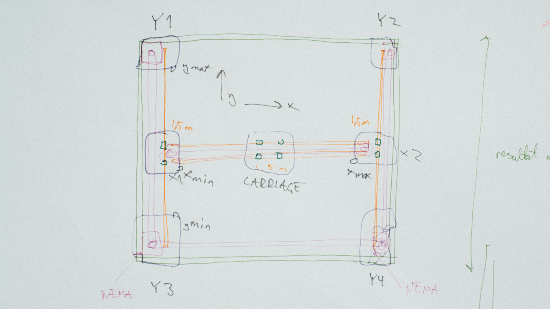
The Corners (Y1 – Y4)
The corners are 3D printed and the main objective for these is to be a sturdy link between the frame on one side and the motors and steel rods on the other.
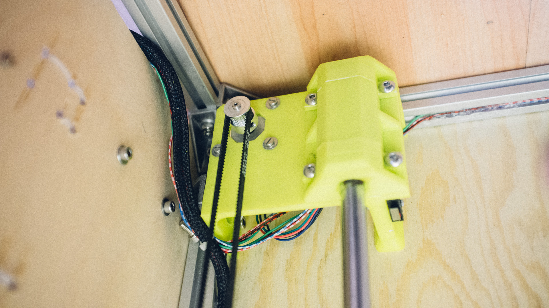
Y1 and Y2 are where the stepper motors are attached. Cogs are attached to the motors’ shafts with set screws. Y1 and Y2 are the exact mirror of each other. These two motors always move in sync and moves the machine along the Y-axis.
Y3 and Y4 are where the other belt cog is placed. Here it rotates freely around an M5 bolt. We recommend using a bolt without threads for this since the cog will wander up and down along the threads in an undesirable manner. Y3 and Y4 are also the exact mirror of each other.
In all four corners we have also have attached 3D printed “chests” which hold the 12mm steel rods in place.
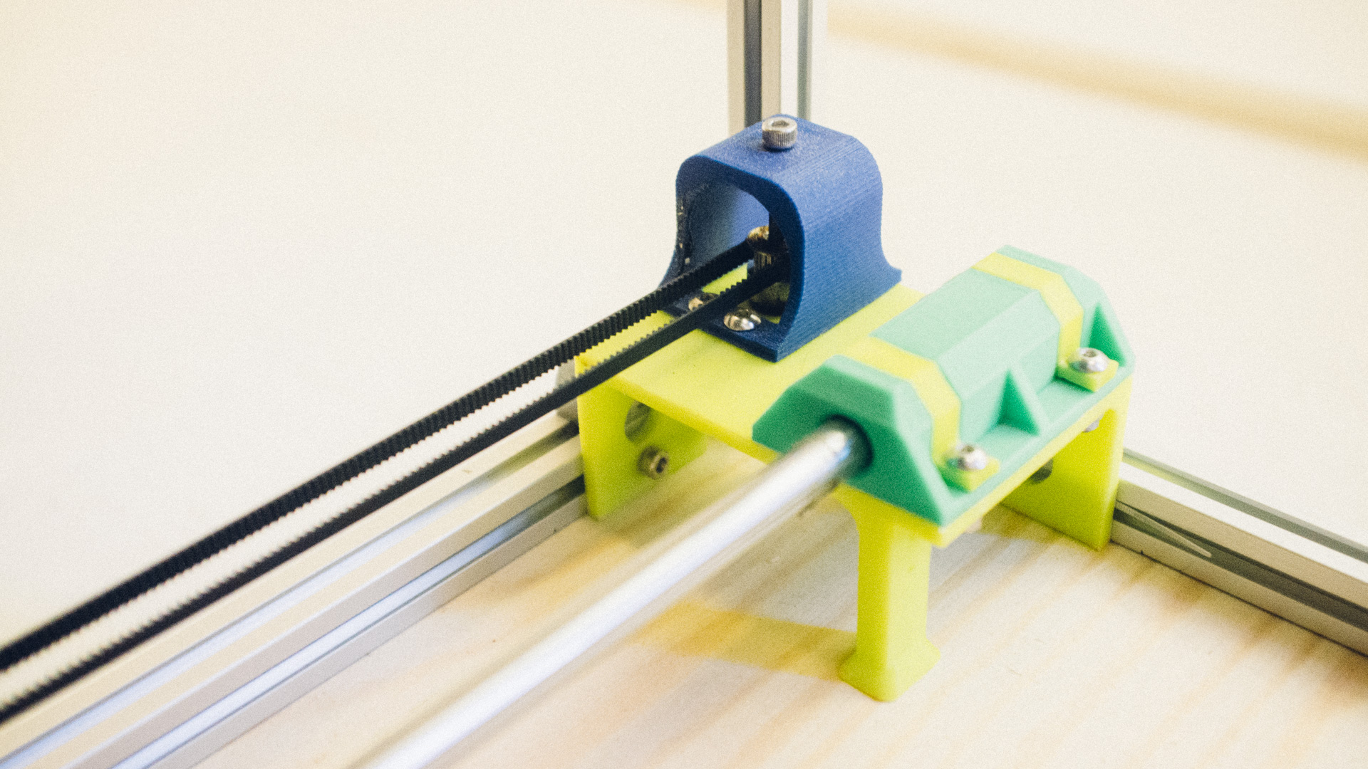
The “Tanks” (X1 & X2)
Named such due to their relatively massive size, the Tanks’ main objective is to move up and down the Y-axis and be the base for everything related to movement along the X-axis. X1 and X2 are attached to one steel rod each via two linear bearings fastened with zip ties.
We have also fastened the end of the Y-axis belts on the Tanks and we are able to tighten the belts via a couple of screws.
X1 is the base for the stepper motor which moves the machine along the X-axis. We have used the exact same principle for movement along the X-axis as with the Y-axis, and we have attached two “chests” on each Tank to keep the two remaining steel rods in place. X2’s function is basically the same as Y3 and Y4’s function.
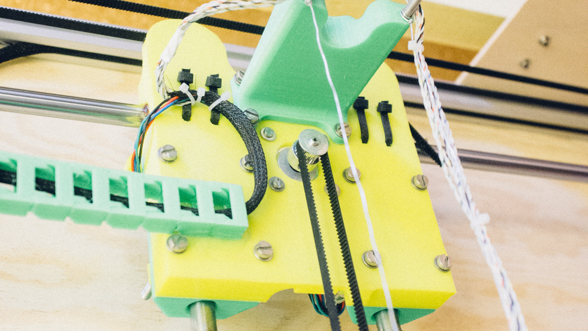
The Carriage
The Carriage is the heart of the machine. It moves along the X-axis on two steel rods and is the base for the servo. Similar to the Tanks, the Carriage is fastened to the rods via linear bearings fastened with zip ties, and the X-axis belt is fastened on the carriage with the possibility to tighten it via a set of screws.
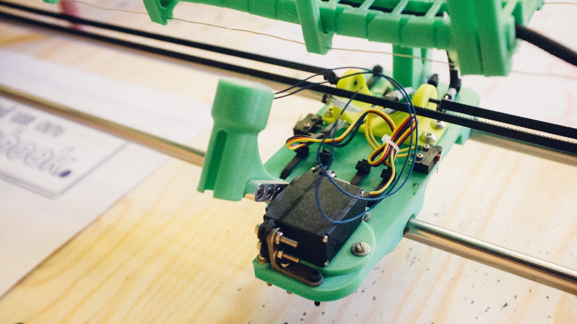
We’re using custom 3D-printed “adapters” for the markers such that every marker looks identical from the machine’s point of view and that we at the same time can fasten several different sized and shaped markers to the adapters. This way we can more easily implement a marker changer system with several marker types. This system is discussed later in this post.
Challenges
Rods
Due to the large span between the rods’ anchor points, the rods will inevitably bend forming a catenary. This curve was something we needed to calculate before starting building the machine to make sure it wouldn’t pose a problem.
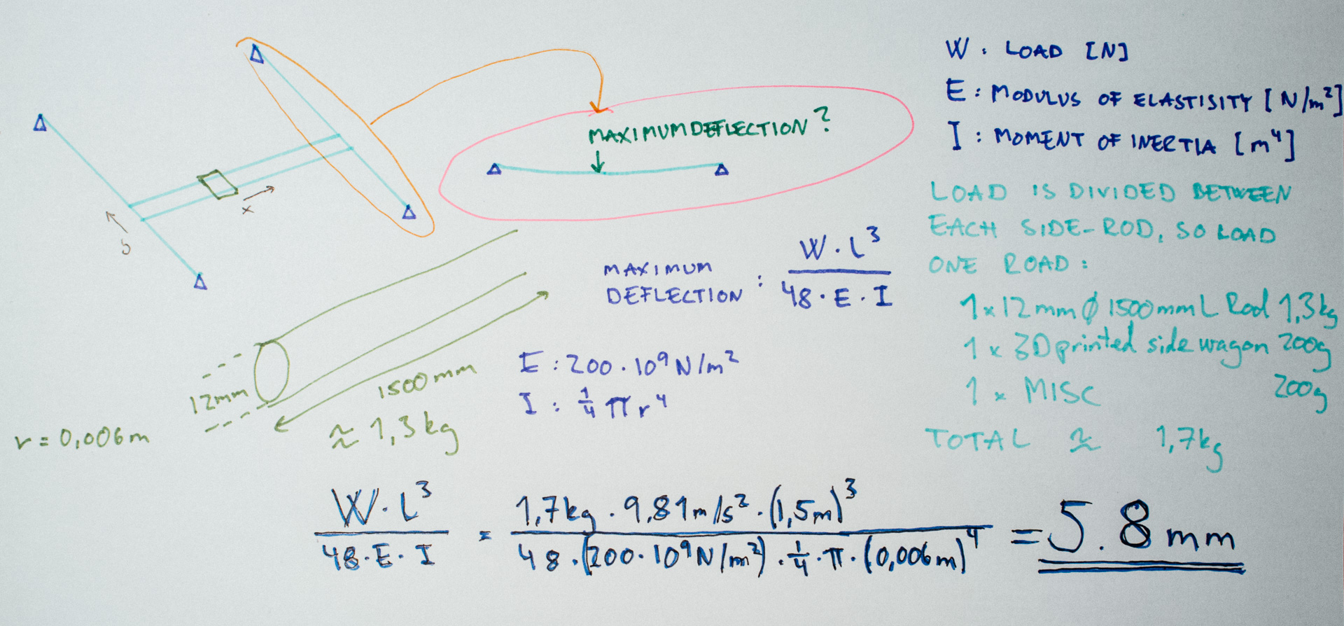
We had to estimate the load (weight) on the rods, and therefore we could only approximate the deflection. 5.8mm is quite a bit, but this is worst case and the marker has a quite flexible tip, so this amount is not unacceptable. We could limit the deflection by using thicker rods along the Y axis (e.g. 15mm) or using dual rods on each side.
Cabling
One thing we hadn’t thought about that much during the design process was how to draw the cables onto the carriage. The Laser Engraver was so small that the stiffness of the braided sleeves was enough to keep then cables suspended and out of the way from the moving parts. With regards to the much larger plotter however, we quickly found out (although after the machine was built) that the braided sleeves wouldn’t be enough to keep the cables suspended.
The solution we came up with, although highly temporary, was to 3D print cable chains we found on Thingiverse. Along the Y-axis the cable chain could easily rest on the wooden back plate, but along the X-axis we had to come up with something else. So, with Trondheim Maker Faire getting close, we made a quick guerilla solution where we built this shady suspended jungle bridge between X1 and X2 consisting of two steel wires, some 3D printed “planks” between the wires and lots of hot melt glue. We attached one end of the cable chain to this bridge and the other end to a retrofitted 3D printed tower on the carriage.
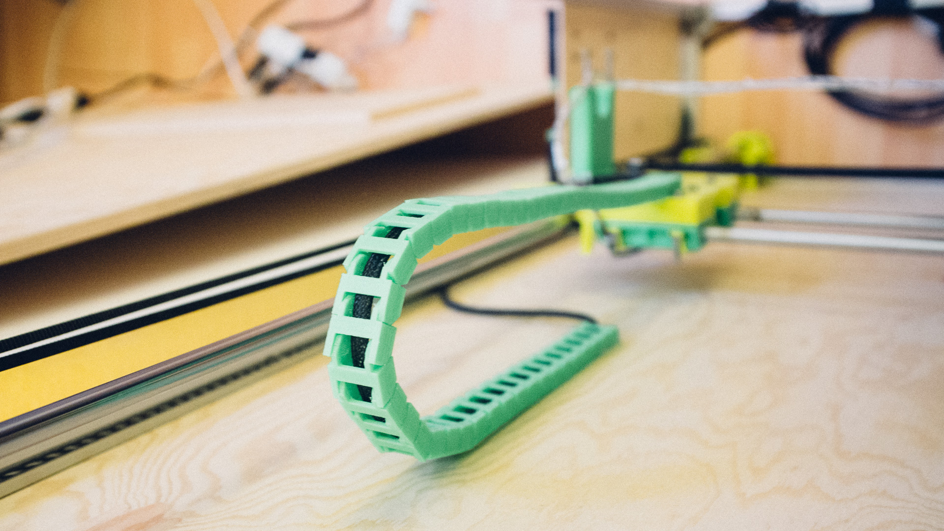
The printed cable chains do the job, but only barely.
Uneven backplate
As mentioned before, the current prototype uses wooden plates as a backplate. They turned out to be a bit uneven, and that made it more difficult to callibrate the height of the marker. To be able to draw across the whole area, the marker will have to push hard into the paper some places and barely touch the paper in other areas. We also have a crack between the two plates we used which we haven’t dealt with yet. We could’ve used some kind of filler between the plates, but it would probably fracture due to a relatively high wobbliness factor.
Future improvements
Cabling
We plan to upgrade our 3D printed cable chains with proper industrial cable chains. And instead of the suspended jungle bridge, we will use something more rigid, maybe another aluminium profile.
Pen Changing
As mentioned in the Overview post, we’ve had plans for the plotter to automatically switch out pens while drawing since the start of the design process. Additional pens will be slotted in a “garage” attached to the frame. This will be a modular design with four slots per garage where we can add several garage modules if needed.
While operating the plotter in interactive mode, we will add pen switching buttons in the drawing program, and the program will send tooling change commands to the machine. While drawing vector graphics, the G-code will contain pre-planned tooling change lines.
Initially, we wanted a kind of tug of war between two small permanent magnets on the garage side, and a permanent magnet and an electromagnet on the carriage side. The carriage side would win if we would apply current to the electromagnet, and the garage side would win if not. This way we could easily, in theory, control if a pen should be fetched from or placed into the garage.
However, the electromagnet turned out to be way too weak, so we have come up with a different solution where a servo mechanism will lock or unlock all the pens at once such that the carriage can come to fetch or place pens at will.
Motor Upgrade
Another thing we thought of from the beginning was to have enough room to upgrade the motors. We are currently using NEMA 17 stepper motors, but we have room to upgrade to NEMA 23. And this is something we will do in the future since the NEMA 17 motors are not strong enough to actuate the machine while it’s tilted.
Back Plate Upgrade
One single rigid back plate would be optimal, but we have yet to find a good solution to this.
Next up
Click here to read the next post where we cover the electronics!
Further reading:
Part 4: Software and Firmware
Part 5: Final