This post will explain the electronics taking part of the big Plotter. First we will explain the whole system: what it consists of and how it’s all connected together, before we go more in depth on some of the components.
Electronics Overview
The system consists of these main components:
- Motherboard. This component is parsing the incoming commands and sends them to the appropriate motor. It also reads the different buttons and act according to the input given. In the future this module is also going to be the brain behind the tool changing operations.
- Power Supply.
- Stepper Motor Drivers.
- Stepper Motors.
- Servo Motor.
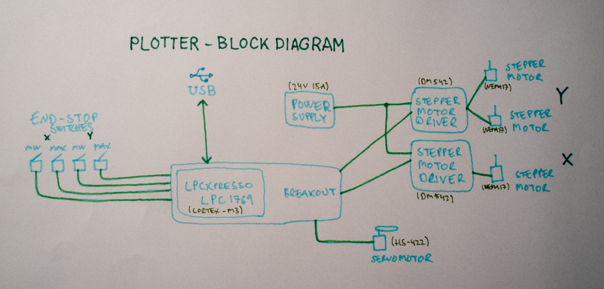
They are all connected together as shown in this picture:
Modules
Motherboard
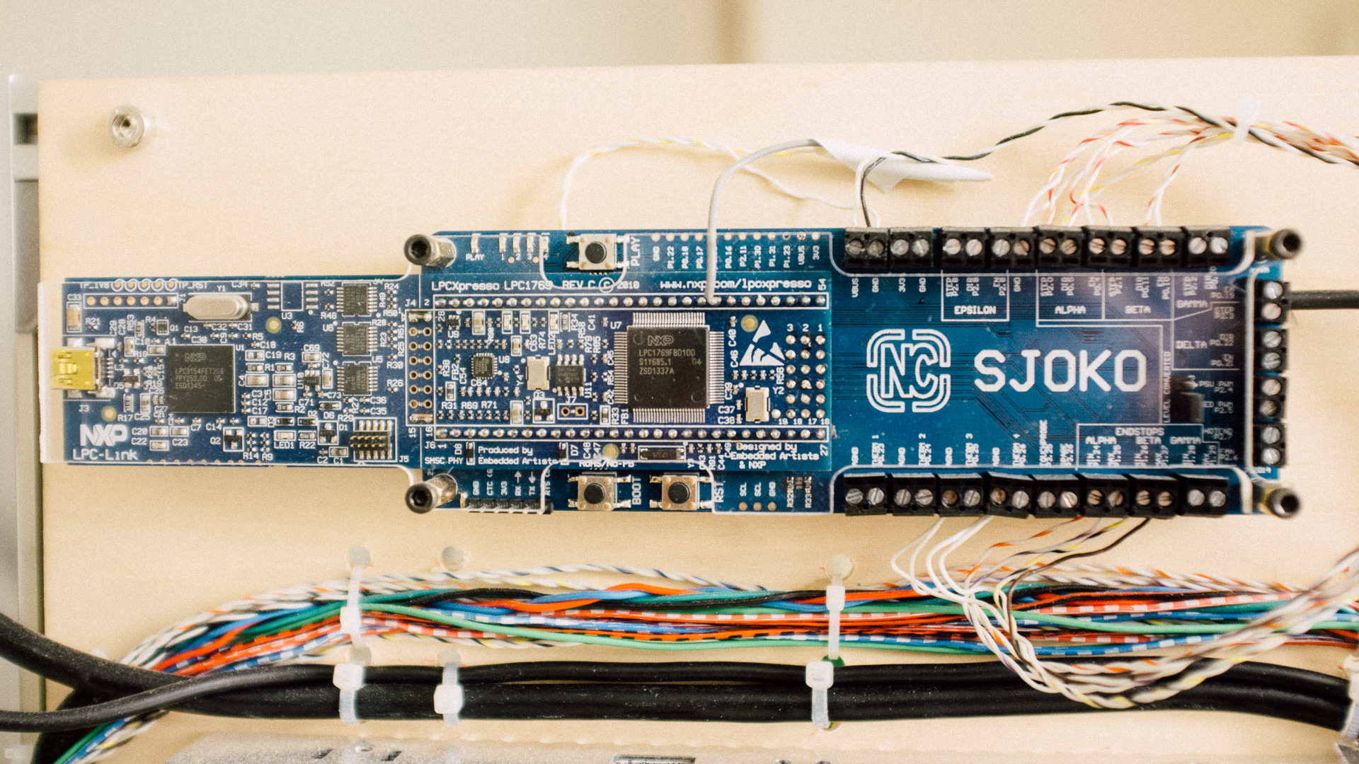
The Motherboard is built around a LPCXpresso 1769 which is a development board for NXP’s LPC1769, a Cortex-M3 based chip running at 120MHz.
To making it easier to use with smoothieware (a G-code interpreter and CNC controller), and easier to incorporate in systems like this, we made a simple breakout-board for the LPCXpresso. The board contains things like level converters, a micro SD card connector, a bunch of screw terminals, leds and buttons.
Power Supply
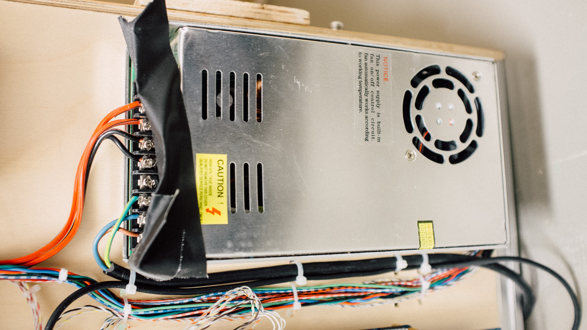
The Power Supply is just a regular AC to DC supply delivering 24 volts up to 15 Amps. It’s used to power the stepper motor drivers and the motors. The motherboard is powered (over USB) from the attached computer, and the motherboard controls the stepper motor drivers through optocouplers, so the Motherboard is completely galvanicly isolated from this Power Supply.
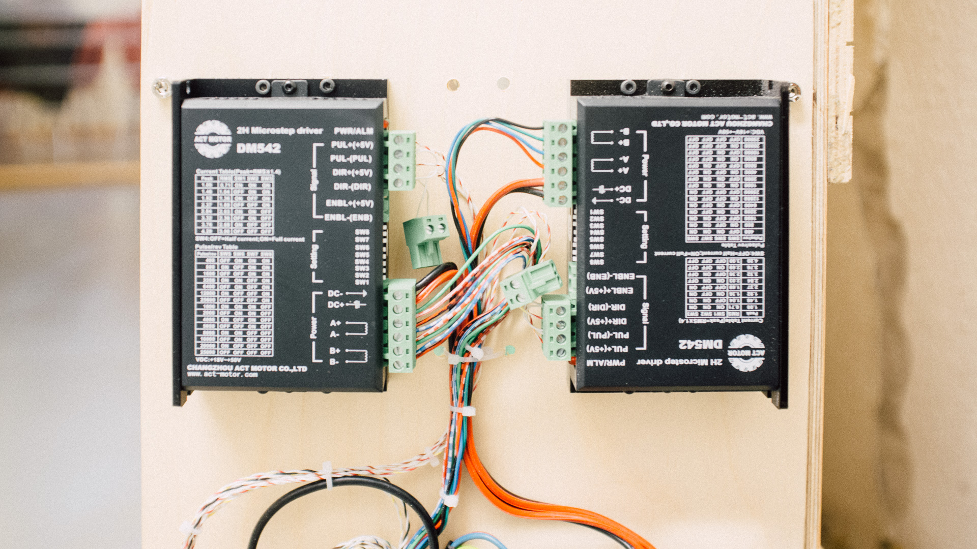
Stepper Motor Drivers
Just as on the Laser Engraver, this machine contains a couple of DM542 stepper motor drivers. One of the driver drives both of the NEMA 17 y-axis motors, while the other is taking care moving the x-axis motor.
The drivers can handle up to 4.2 Amps each. This will not be an issue when we upgrade to NEMA 23, as long as we add another driver so that the y-axis driver doesn’t need to drive two motors.
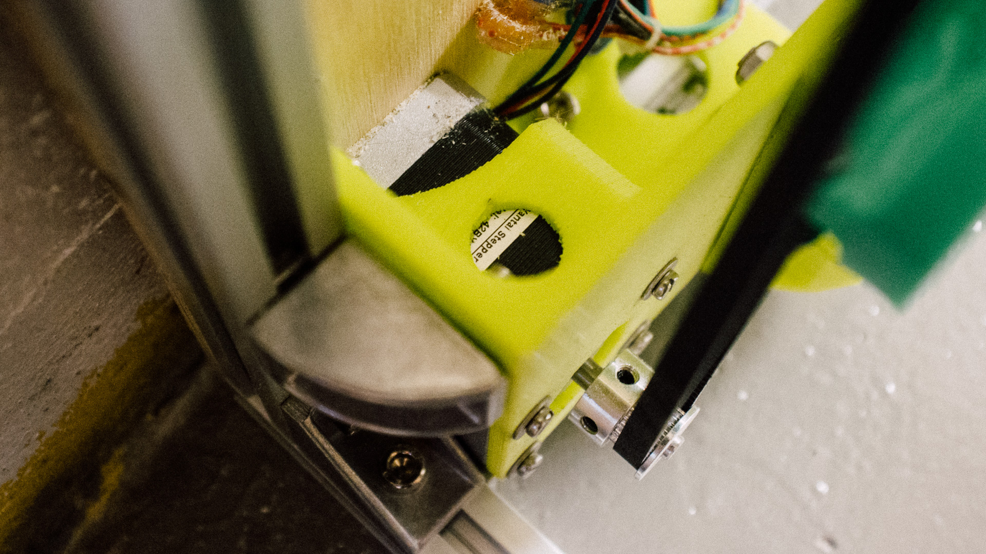
Stepper Motors
As explained in the last post about the mechanical design, the machine movement is actuated by 3 NEMA 17 motors (and a servo).
Since two motors are driving the Y-axis in parallel it’s of grave importance that the two y-axis driving pulleys is of the exact same dimensions. Or else you will end up with some of the challenges we had when building the laser engraver.
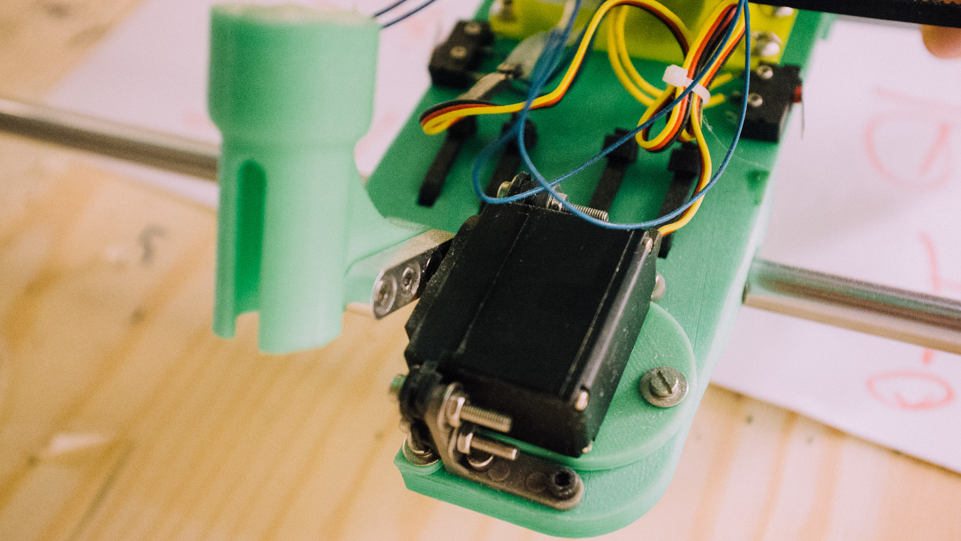
Servo Motor
We used a standard Hitec HS-422 servo motor. It gets its power and control (PWM) from the Motherboard. Since this is a somewhat long distance to travel for the 5V PWM, it’s important to shield and make this signal travel as light as possible!
Or else you will have an uncontrollable and shaking servo…
Click here to read the next post where we go into the software and firmware running this machine.
You can read more about this series of post in this overview.
Further reading:
Part 2: Mechanical
Part 4: Software and Firmware
Part 5: Final