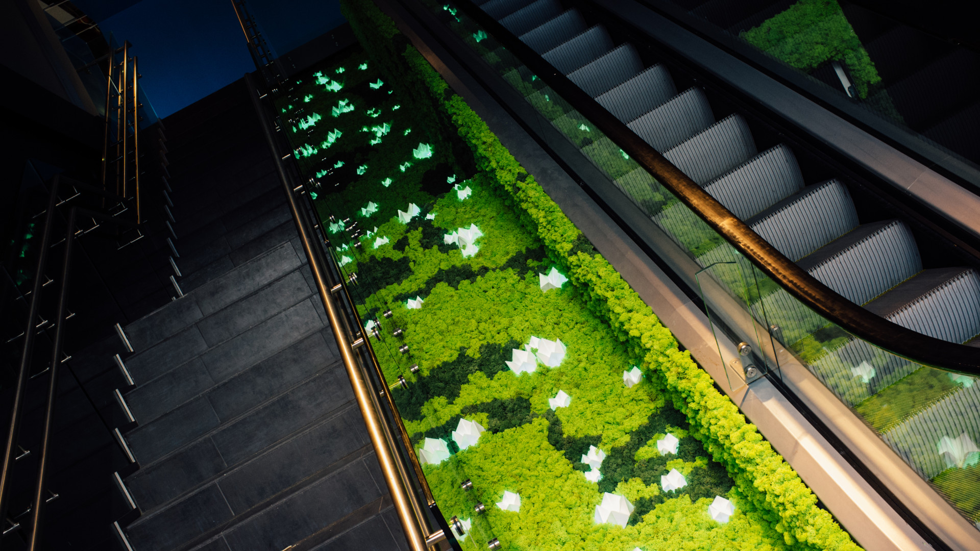
NICE and Bjørke Arkitektur had this awesome idea on how to create a really mesmerizing entrance at Trondheim’s new tourist information, named Visit Trondheim. It should among other things include a moss coated interactive LED installation. As you may know, LEDs is something we really like working with here at Norwegian Creations. And luckily for us, Bjørke and NICE knew this, so they let us take part of this awesome project!

Together we created a concept for how it should work, including things such as sensor inputs and how the LEDs should react to different events in the environment.
What LEDs to use?
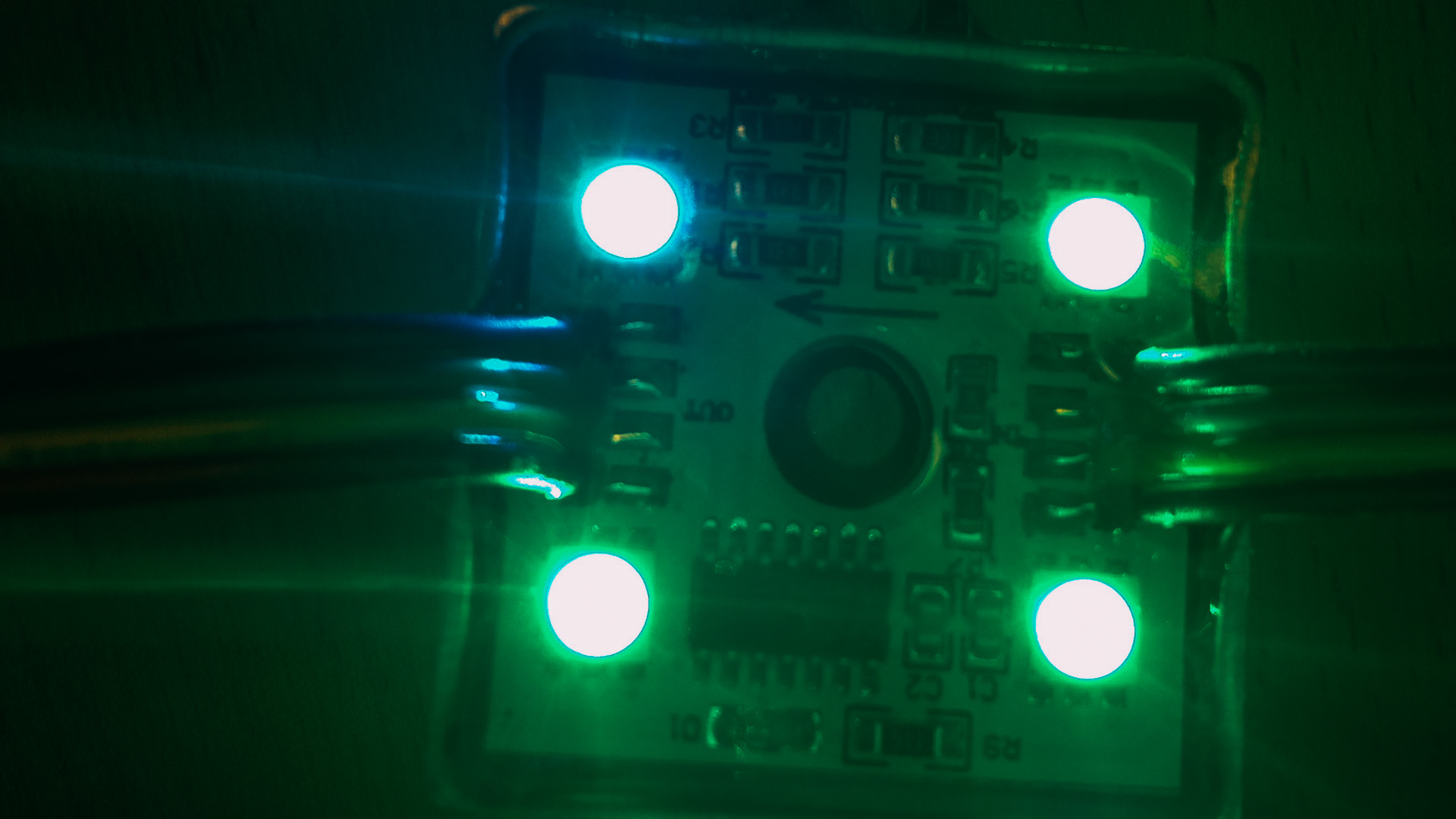
The moss is both dead and coated with an anti-flammable layer. We had to both find the necessary brightness to shine through a layer of moss and the required number of individually controllable points of light. Since the LEDs was going to take part in a bigger installation (underneath the moss etc.), it was not necessary that the number of LEDs was so high that it would have made it into an attraction in itself. The field to cover was about 11 meters long and 1 meter wide, and after some LPM2 (LEDs per Meter Squared) calculations we found out that a total amount of 400 individual controllable RGB LEDs was appropriate (36.4 LPM2). And after the required LED brightness and heat tests, we landed on using 0.96W individually controllable modules, each consisting ofour 5050 RGB LEDs. These modules needs 12V and SPI-like command data.
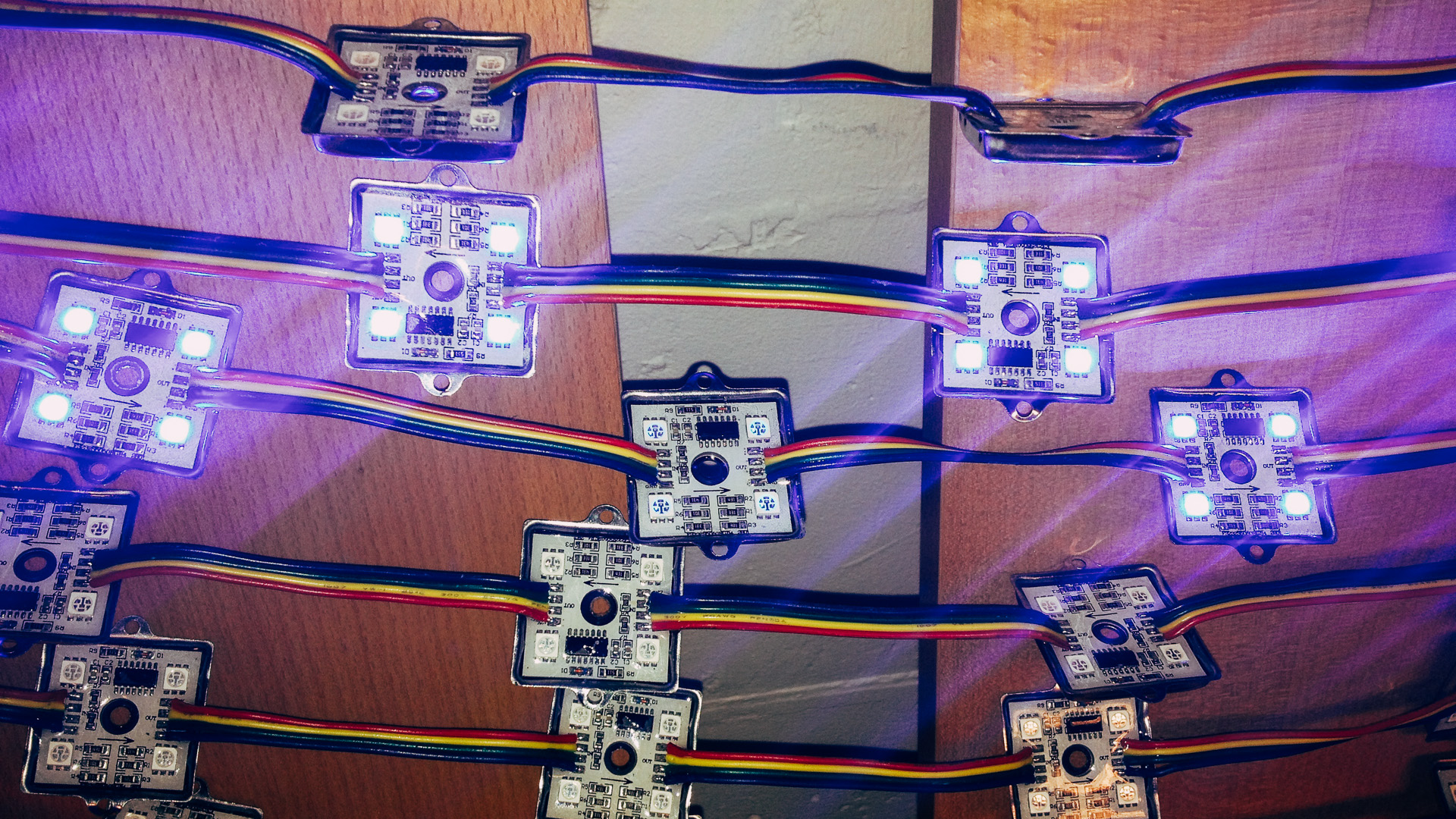
When using LEDs from a supplier with unknown validation procedures, it’s important to test them thoroughly before installation. And especially when they are going to be installed on a place where it’s rather unfavourable to do quick fixes. So we decided early that we needed to test all LEDs extensively together with as much of the electrical environment as the LEDs where going to be installed in as possible.
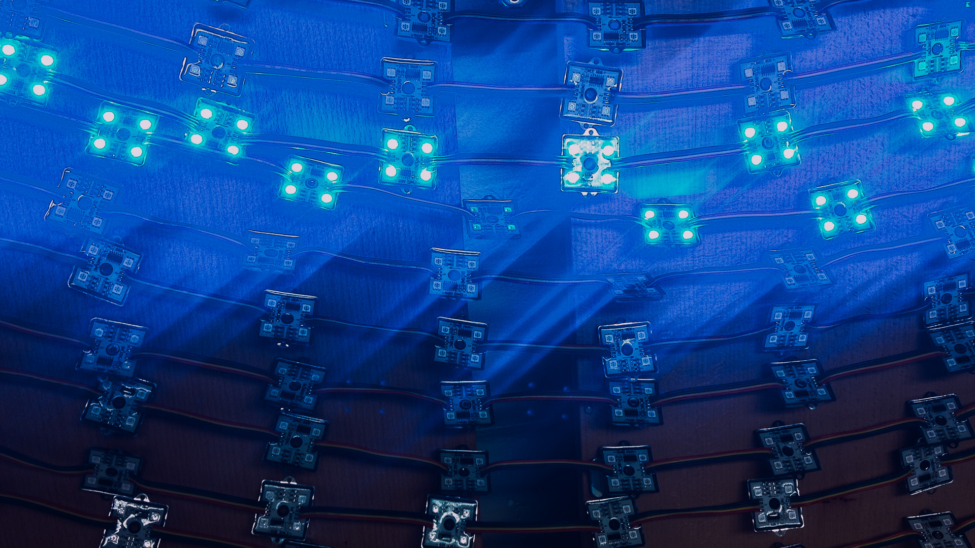
The most important factor here is without no doubt the power supplies. 400 LEDs, each drawing 0.96 watts at 12 volts, means that the system need continually 32A @ 12V. And you do not try to save cost on cheap power supplies! We scaled this power requirement with a factor of 2, and ended up with 4 high end power supplies each capable of delivering 16A @ 12V. The LED testing spanned over three weeks with different slow changing colour patterns.
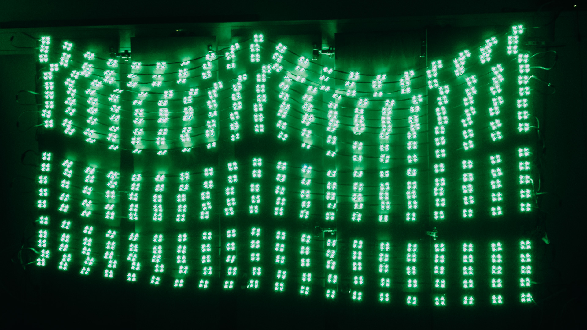
In this phase we discovered several faulty LEDs, either modules with problems with some of the colours or modules that stopped accepting the never-ending data signal.
The embedded system
As this long-term test of the LEDs unfolded, we designed, created and assembled a control system for this installation.
Hardware
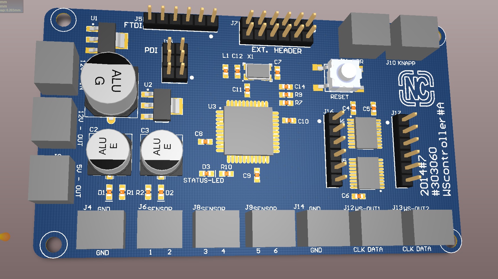
The main controller is based around an AVR ATXmega128D4 8-bit microcontroller. The LEDs have an SPI-like protocol that uses one serial data line and one clock line. To send out this data with minimal CPU usage we use the integrated SPI module in the microcontroller. Since the Xmega has 3.3V logic levels and the LEDs has 5V, we implemented a level converter (U6 in the picture below). After the level converter we use a combined buffer & line driver to ensure a good signal over long cable runs (U5 in the picture below). We also mounted a header to an FTDI breakout for easy debugging over UART and one extension header if we later would want to expand the system. The sensors we are using has an “NPN Open collector output” which means we could use a single I/O -pin for each sensor.
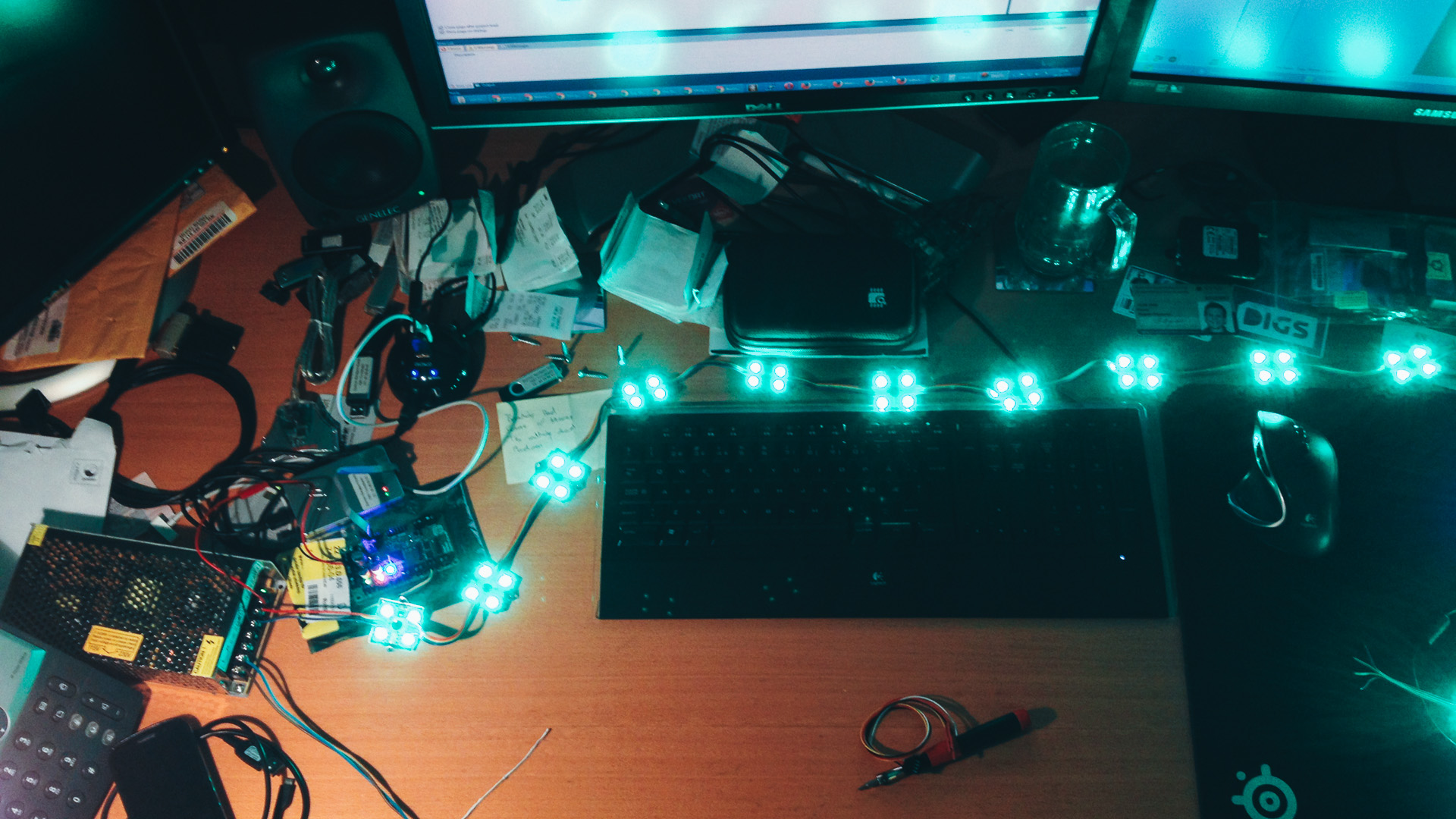
Testing the created hardware is important, and part of it took place on my rather clean desk:
Firmware
We ran the controller at max speed (32MHz). It has only 8 kilobyte of RAM, so some pretty nifty algorithms had to be implemented to make this controller able to handle all the real time colour merging and pattern generation. The system generates among other things something we call chasers. These are a smooth moving patterns consisting of a head, a mid section and a tail. Each section has its own length, and the head and tail is sections where the intensity is fading up or down. Each chaser do also have unique attributes such as speed and colour. And when different patterns meet, colours has to be blended!
Maybe you think that colour blending is trivial and that it is a “mathematical correct” way to do it, but it’s not! After a few hours of studying colour theory and Luminance, we started experimenting with the look. Because when it comes to this, it is not about what’s “correct”, but rather what looks good!
We decided that premultiplied alpha blending looked best in this application. And it was implemented like this:
col_t CHASER_RGB_blend(col_t first, col_t second)
{
	col_t ans = {0};

	// Premultiplied Alpha Blending
	// Add the new col to 50% of the old
	ans.R = (uint8_t) (0.5 * (float)first.R) + (float)second.R);
	ans.G = (uint8_t) (0.5 * (float)first.G) + (float)second.G);
	ans.B = (uint8_t) (0.5 * (float)first.B) + (float)second.B);

	return ans;
}
As you can see in the video around 1:44, we had a long design session where we created a wide range of different programs. These were programs that were going to be triggered when the different sensors picked up interesting events. We landed on about 20 different “approved” programs (chasers, “stars”, etc.) for each event. They were all allocated a probability to trigger, so there exists some rather intense and exciting programs to occur with a chance less than 0.1% when a sensor event is triggered.
Installation

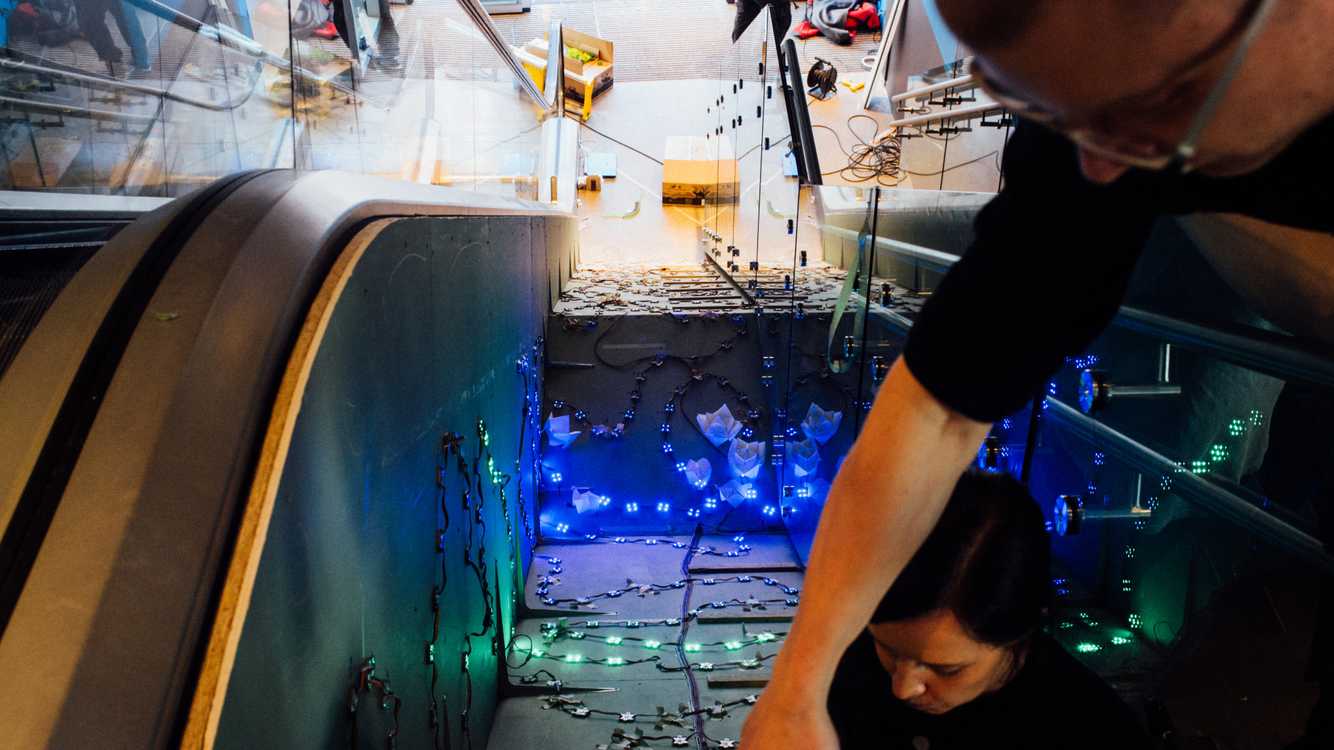
First we attached all the LEDs and recorded their position in the plane. The firmware has to know these positions to be able to drive the different moving patterns with a constant speed relative to the surface.
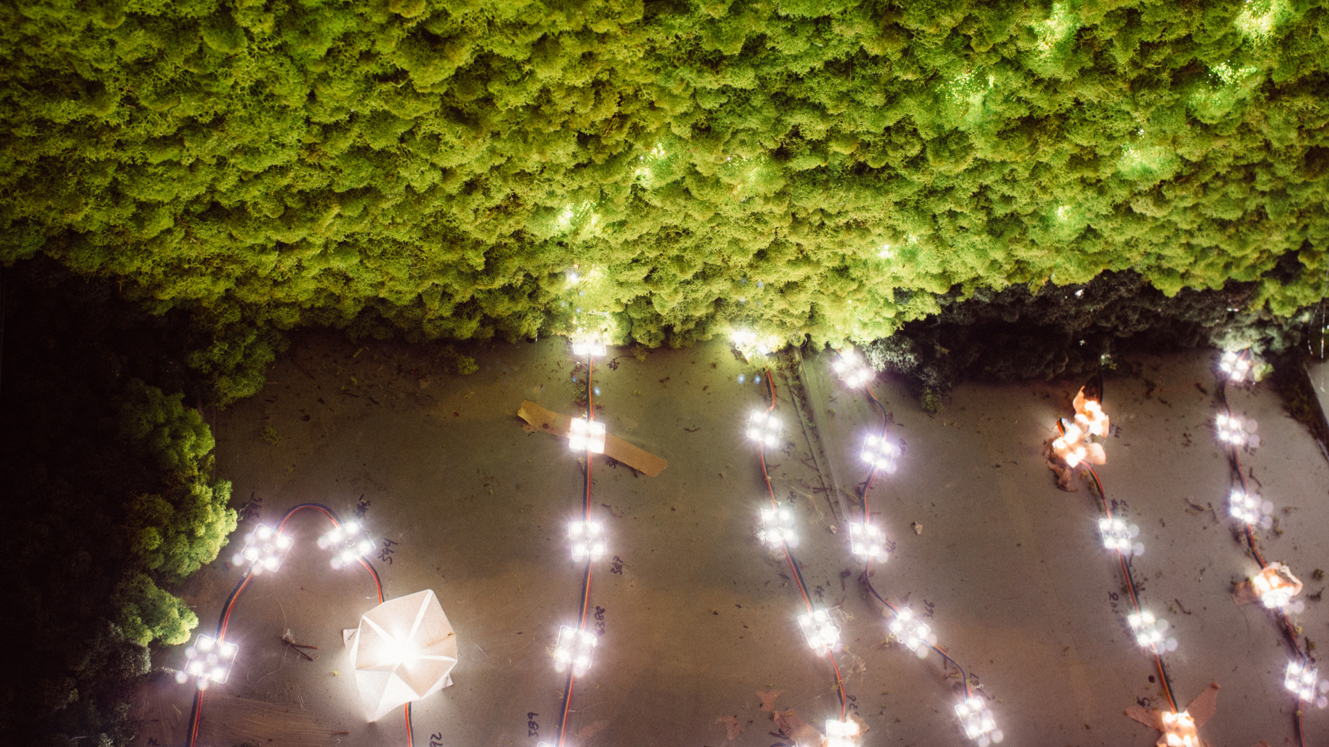
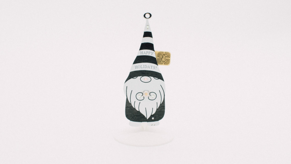
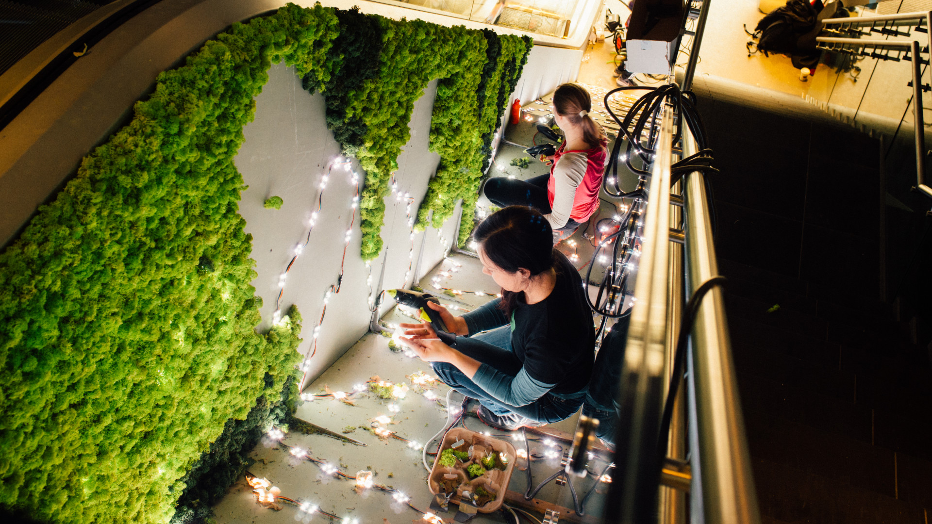
Thereafter, the moss laying began! This was handled by NICE and Bjørke Arkitektur, and was rather exciting to look at. As you can see in the picture above, an LED is covered under a paper fortuneteller. The installation consists of several of these points, and they are all handled different than the moss covered LEDs. A chaser can for example have different colour on the moss covered LEDs and these Tower-LEDs.
Underneath this mossy front, we installed the control system.
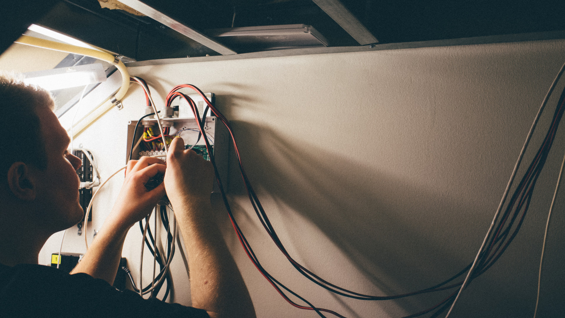
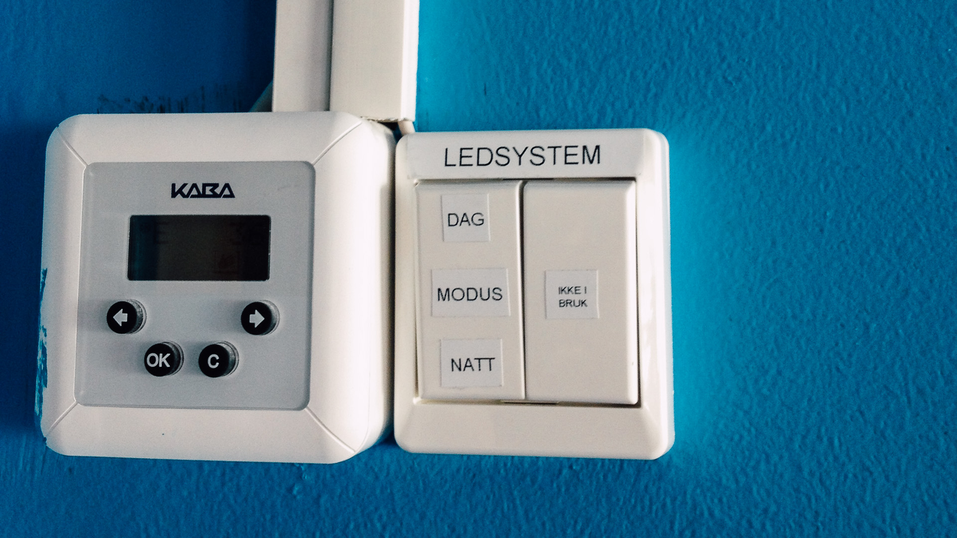
The system does also include several installed sensors and some buttons. These buttons give the centre operators a way to control the state. Since the system reacts differently when in night mode (reacts to outside activity instead of indoor events), this was important to install.
The system has now been running 24/7 since the grand opening on March 25th 2014, and everything works perfect. 🙂
So if you are in Trondheim, Norway, you should check it out in Nordre Gate 11.