A Logic Analyzer is an instrument that records (and displays) multiple digital signals. This instrument gives you several important benefits, such as timing analysis and protocol decoding. You can also get more “general assistance“, often in the form of clever signal triggering, for everyday tasks.
This post is a 101 introduction to this magic instrument, and we will look further into some of the features mentioned above!
Weapon of choice
In this blogpost we use the old PC-based Saleae Logic 8 Logic Analyzer. This is a small Logic Analyzer with 8 channels. In the newest Logic 8, all the channels can be used to capture analog signal levels as well. But this one is only digital!
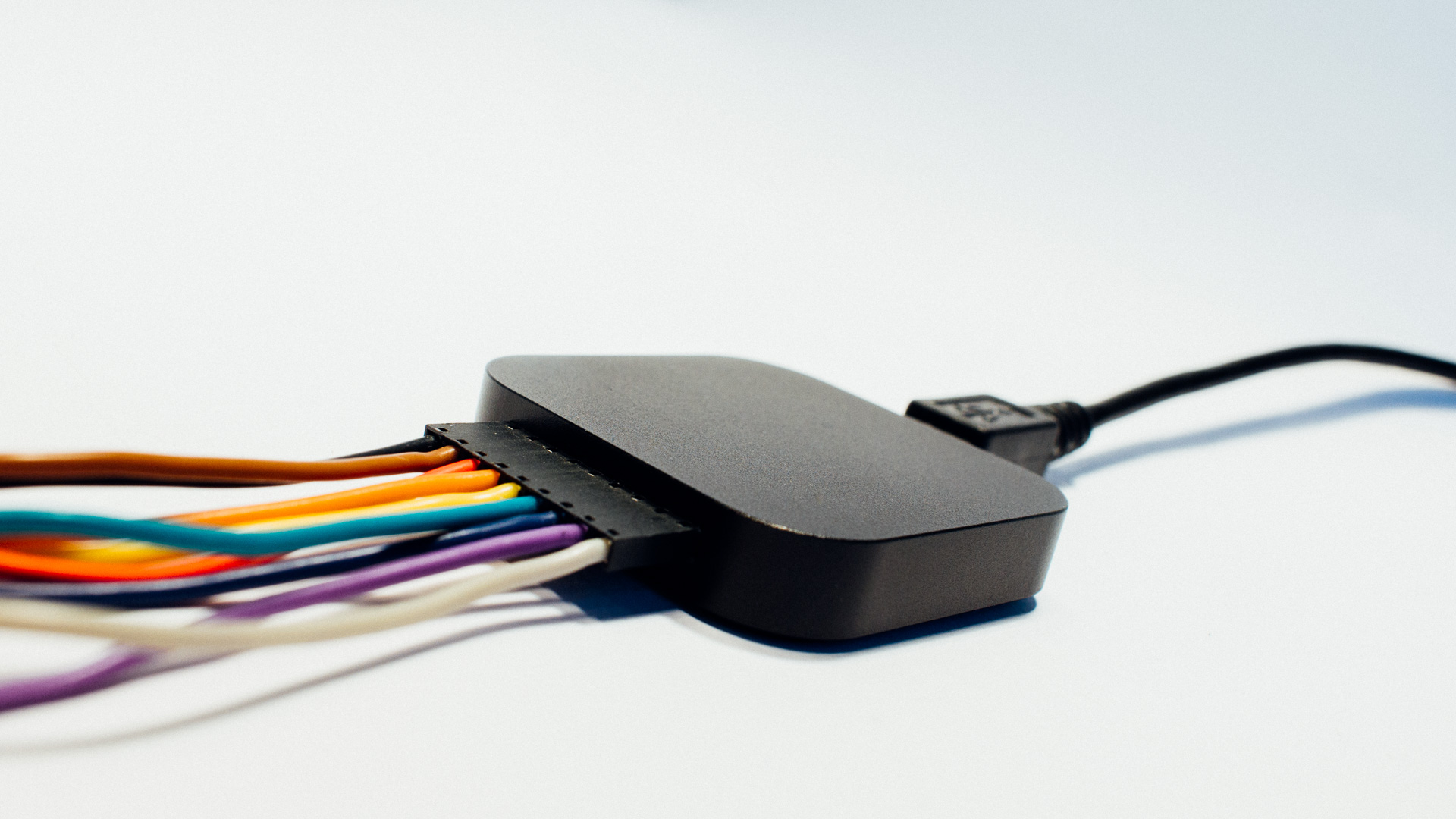
The Logic Analyzer only gives out a “one or zero” signal on the different channels. In combination with your circuit this is possible because the internal electronics in the analyzer change state (0 vs 1) at approximately the same voltage level that your digital system does.
When it comes to Logic Analyzers we often see the two main types: Portable and PC-based.
Portable Logic Analyzers
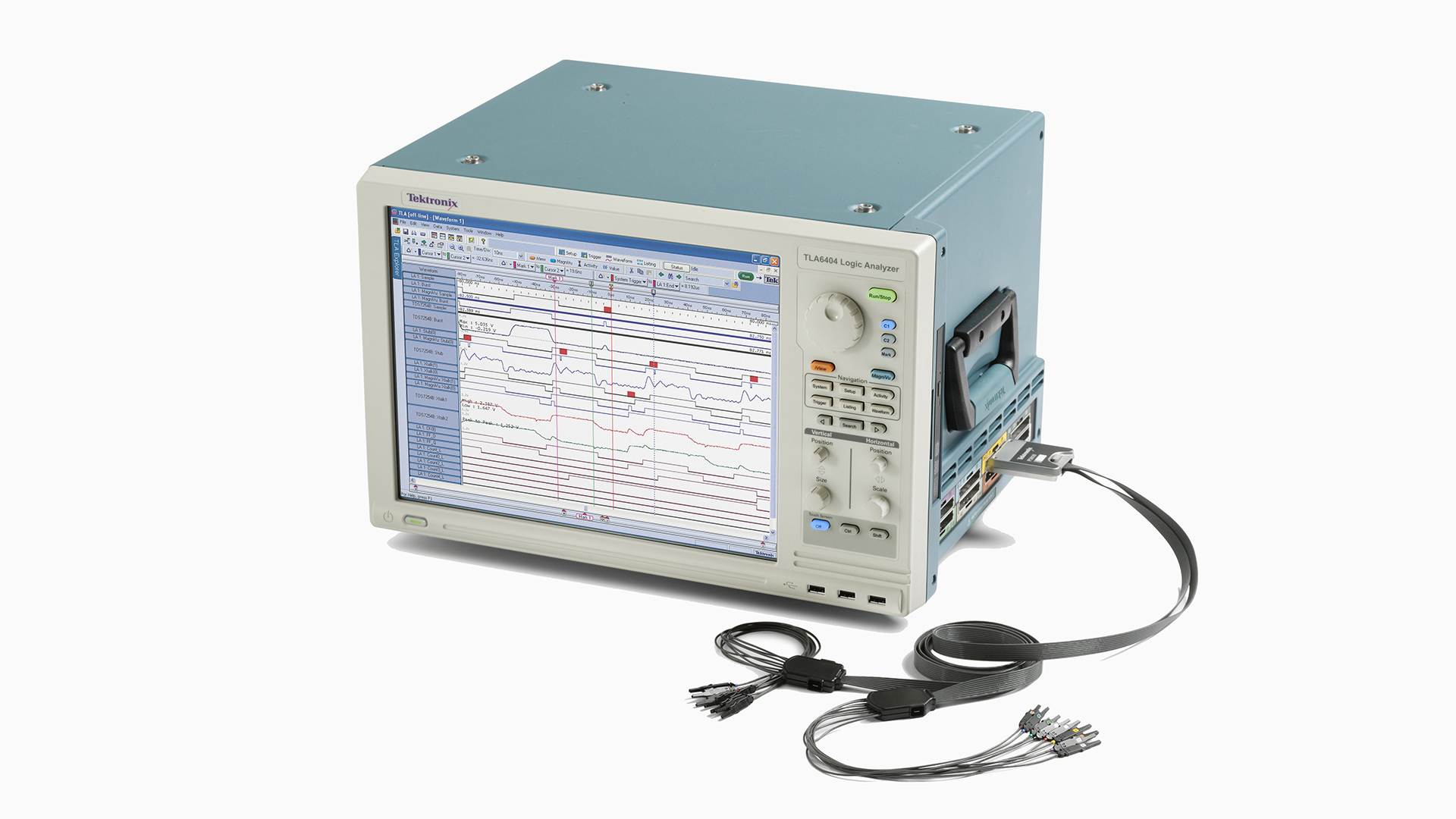
A fully Portable Logic Analyzer contains everything you need: probes, signal front end, neccessary HW to run the SW (“computer inside”), display etc.
PC-based Logic Analyzers
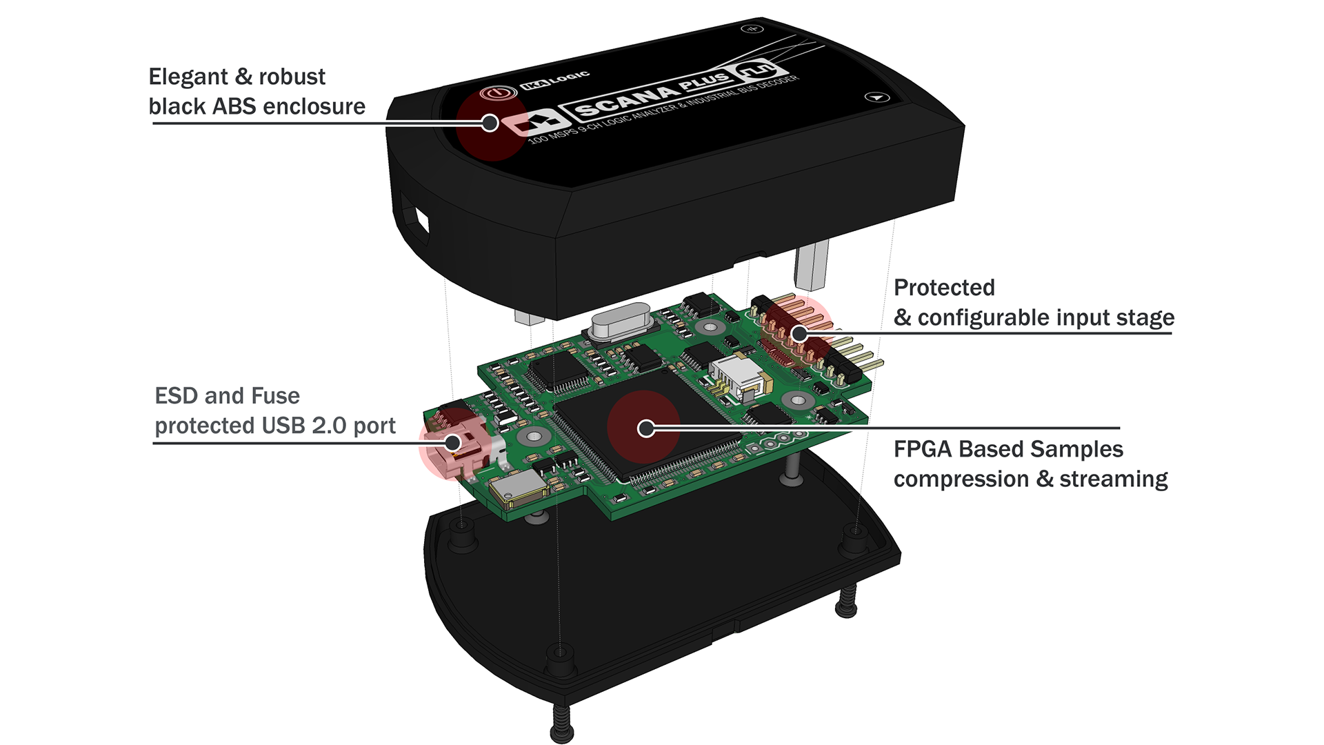
On the other hand we have PC-based Logic Analyzers. They contain only the probes, capturing circuits and neccessary HW to tidy things up and send the connected PC the signals for further processing.
The software helping the user runs on a connected PC (or device). The software is responsible for displaying the results (all the important stuff) and helping you configuring things such as triggering, protocol decoders etc.
Other options
There exist several ways to approach logic analyzing heaven! A regular way is through a mixed signal oscilloscope. Several suppliers also make solutions that connect to tablets and devices like that. E.g. Oscium.
Simple Usage: Timing Analysis
The maybe most important aspect of Logic Analyzing is Timing Examination.
By that we mean how different signals behave BOTH relative to each other AND to time.
Example
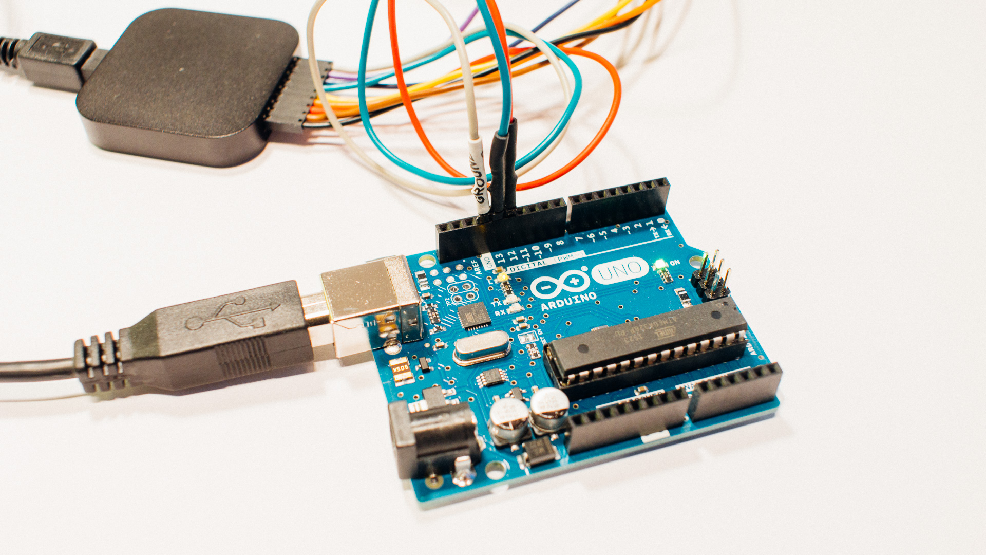
In this (and the next) example we will use the old version of the Salae Logic 8, the Salae Logic application and an Arduino Uno board to apply the signals.
Connection:
- Saleae GND <-> GND on the Arduino UNO
- Saleae RED <-> Pin 12 on the Arduino UNO
- Saleae GREEN <-> Pin 13 on the Arduino UNO
We want to apply a signal where the two pins on the Arduino (12 an 13) goes up and down on a known interval, and we want to confirm that with the Logic Analyzer. To do that we program the Arduino as following:
void setup() {
  pinMode(12, OUTPUT);
  pinMode(13, OUTPUT);
}

void loop() {
  digitalWrite(12, HIGH);
  delay(10);
  digitalWrite(13, HIGH);
  delay(50);
  digitalWrite(12, LOW);
  delay(10);
  digitalWrite(13, LOW);
  delay(50);
}
And here is the screenshot from the Saleae Logic software:
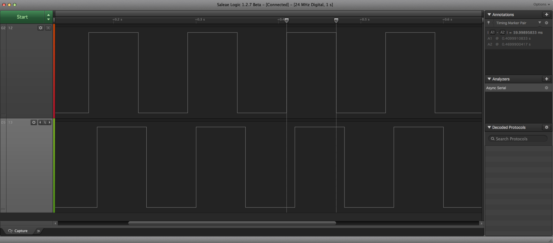
As you can see we used the Logic Analyzer to confirm that:
- Pin 12 goes high first
- Pin 13 goes high 10 ms later.
- Pin 12 goes low 50 ms later.
- Pin 13 goes low 10 ms later.
- Pin 12 goes high after it has been low in 60 ms.
- Go to top!
Medium Skill Level: Digital Protocol Decoding
An important feature of Logic Analyzing is the ability to decode different digital protocols!
In this example we are going to use the standard UART (serial) output from the Arduino.
Why not include the serial input on the Arduino? That’s because nothing happens there! A regular Logic Analyzer is only made for looking at signals, not apply them! And since we don’t have anything else connected it’s only the things going out from the Arduino board that are of interest.
You can read more about digital communication in this blog post!
Example
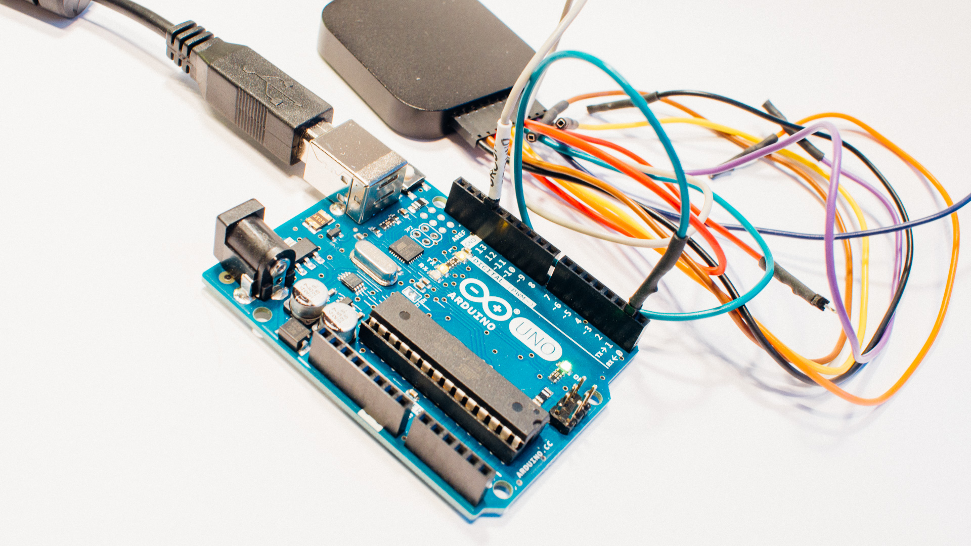
We are modifying both the code running on the Arduino and the Logic Analyzer setup. This time the connection looks like this:
- Saleae GND <-> GND on the Arduino UNO
- Saleae GREEN <-> Pin 1 on the Arduino UNO (TX->)
We want to send a known serial communication signal, and we do that by programming the Arduino Uno with the following firmware:
void setup() {
  Serial.begin(9600);
}

void loop() {
  Serial.write("Hello World!");
  delay(50);
}
This will open a Serial link (UART) on Pin 0 (RX) and 1 (TX) with “common” settings and a baud rate at 9600.
The next step is happening in the Logic Analyzer software:
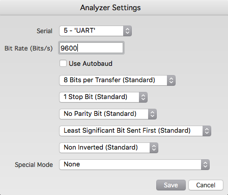
Here will different Logic Analyzer solutions of course look different. Saleae has an “Add Analyzer” function for doing this. Using that, you can first select between known communication protocols such as I2C, Async. Serial (used here) and SPI. But the list does also includes protocols such as Modbus and LIN and it is possible to add your own protocol decoding software if you want to do that!
After you have selected the appropriate protocol you will get a more in-depth setup screen based on the selected communication method. What we selected is shown in the picture above!
When you have selected the appropriate stuff, you have to trigger a recording, and the software will decode the signal automatically:
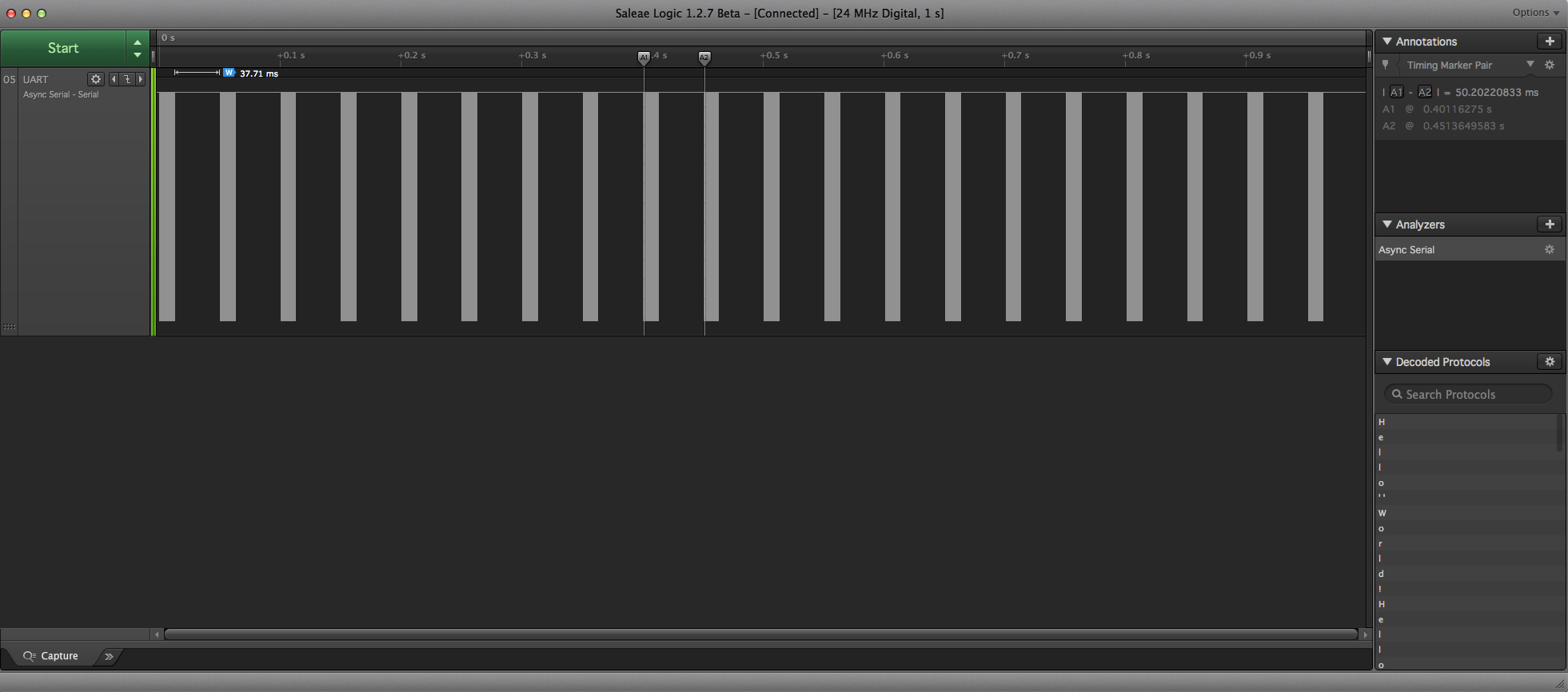
Initially, things are probably not at the appropriate zoom level. But before we zoom in it’s worth to note where the 50 ms gap is!
In the code we wrote that it should insert a delay on 50 ms AFTER serial sending. However, we see with the Logic Analyzer that it actually is 50 ms from the START of a transmission to another START. This means that the serial communication engine in the Ardunino board is running on its own with its own buffer. So the Serial.write() only gives the things you want to send to that module and then he does his thing in the background!
But anyways. Forward! If we zoom further in on a single transmission we find this:
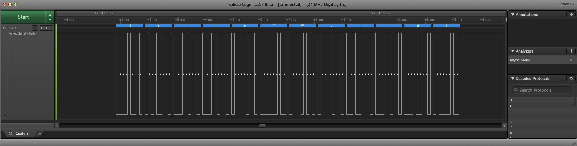
Here we can see the power of the Protocol Decoder. On the top of the signal display you can see several blue fields with the decoded answers inside.
As we can see, “Hello World!” was transmitted and decoded with success! And note that it does NOT automatically send an extra line break at the end here 🙂
Important Tool: Signal Triggering
Signal Triggering is about programming the system to start recording when X happens. If you just record everything that happens between time X and Y, you will get data of a size that is proportionally more difficult to handle based on the total length.
It will both be a challenge for your system to handle it (it does probably have a maximum time limit), and it can be a challenge to find what you are looking for.
You want to start recording (and record for e.g. 100 ms) when simple things like Channel X goes HIGH or Channel X goes LOW. Simple trigging methods like that usually does the job, but sometimes more advanced triggering is needed. For instance you might want to record several signals when a specific I2C message is sent. In this case you need triggering based on a specific signal decoded in one of the Logic Analyzers to do that. And real time protocol decoding is often an expensive feature.
One way to circumvent advanced triggering like this is to have a separate digital channel which only job is to trigger the Logic Analyzer at the correct time. This does of course include new challenges such as more custom firmware and hardware, but can in certain situations be a good choice.
Getting Into This, and Closing Words
As we have seen, Logic Analyzing is a powerful and important tool. But is it expensive?
PC-based Analyzers are cheeper than fully Portable ones. You can get PC-based ones for ~20$+, but fully Portable Standalone Logic Analyzers usually sells for several hundred $ and upwards.
Another rather important side in this equation is the accompanying software! A cheap tool with extremely good software performs often much better than an extremely good tool with crappy software.
And be sure you know how different caveats such as Digital Sample Rate (fastest digital signal) and total Sample Depth affects your situation.