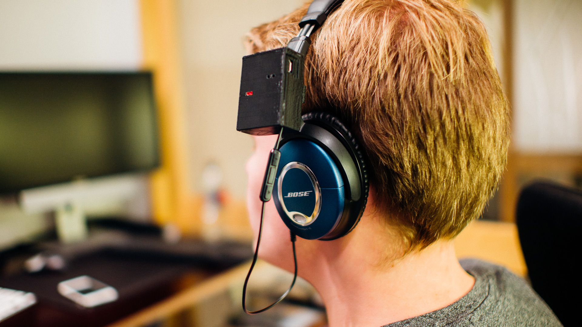
The newest Bose noise cancelling headset, the QC35, has wireless Bluetooth connection. They are also quite pricey. Many already own a pair of QC15 or QC25. If you’re one of these people and want to upgrade to wireless connection without buying a brand new headset, this might be the solution for you!
This post will guide you through how to make your very own Bose Bluetooth module for ~25 USD with chargeable battery, APT-X support and customized casing, among other things. And if you think coding is a chore, you’ll be glad to know that this project is completely coding free! You just assemble the hardware.
What You Need
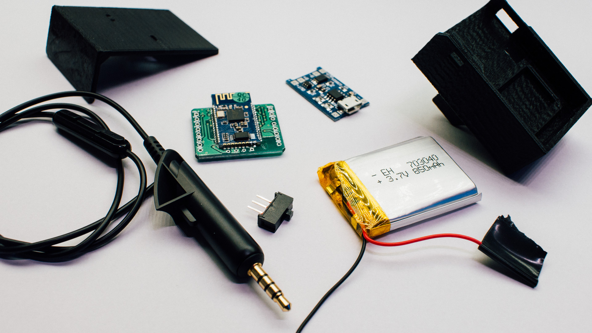
You need the following parts:
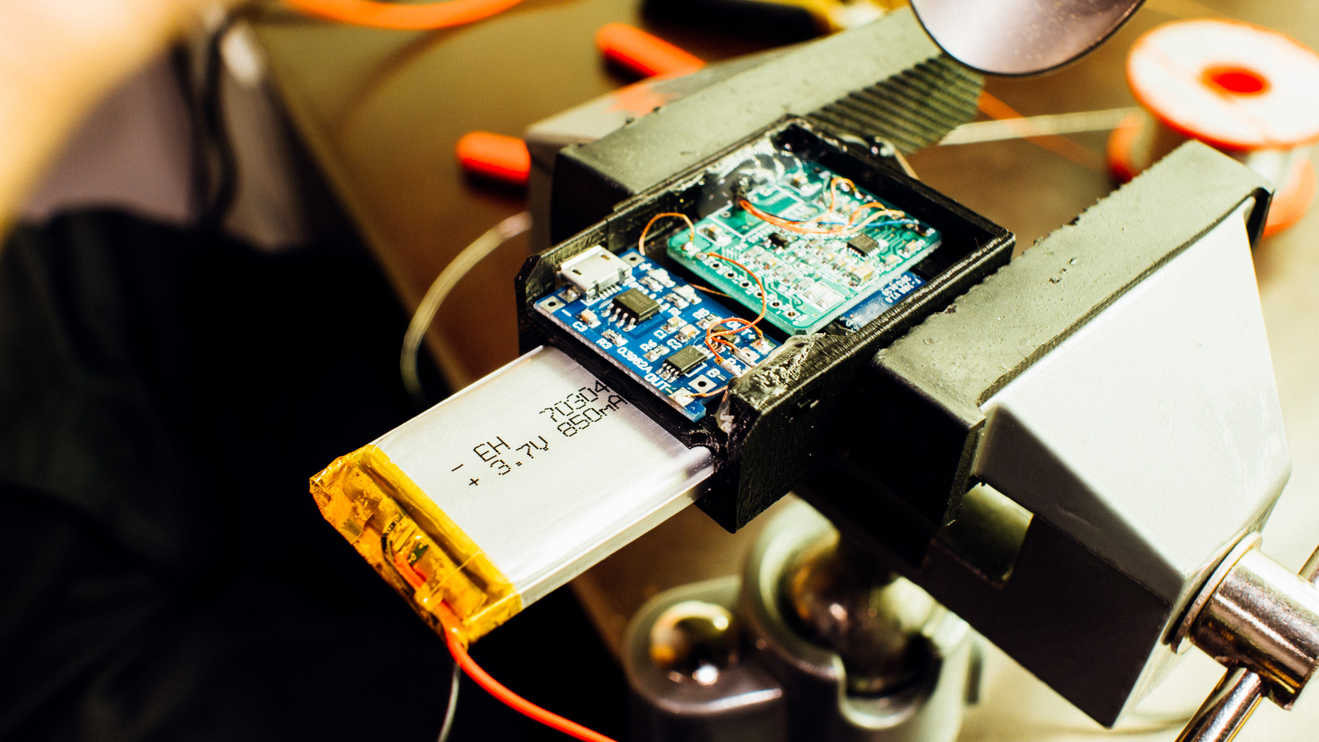
- Battery: 3.7V Litium-Polymer 850mAh, package type “703040”, dimensions: 7mm*30mm*40mm . You could easily buy from ebay.
- Battery charger module: 5V 1A micro USB charging board. Could buy from ebay (search).
- Power switch: We had a switch from Sparkfun laying around, you can buy the same here.
- CSR8645 Bluetooth breakout module: The heart of the system. There exist several different breakout boards on ebay. Here it’s important to buy the correct one (v4.1). Link to a suitable model you can buy (link to search).
- Headphone cable
- 3D printed casing, you can download the design below (we supply both stl and step files!). You can print it at your own printer or send the files to a 3D printing service (like shapeways, i.materialise etc..). If you need to tweak some dimensions, just import the step files into your CAD software and go crazy.
To assemble the Bluetooth module the following tools is nifty to have: 3D-printer, soldering Iron, small wires to use between the boards, cutter and hot glue.
The Casing Design
The casing is where all the electronics are kept in place and what keeps everything mounted to the headset with a nice interface.
Note: when describing directions in this chapter we use the coordinate system where the casing is mounted on the headset.
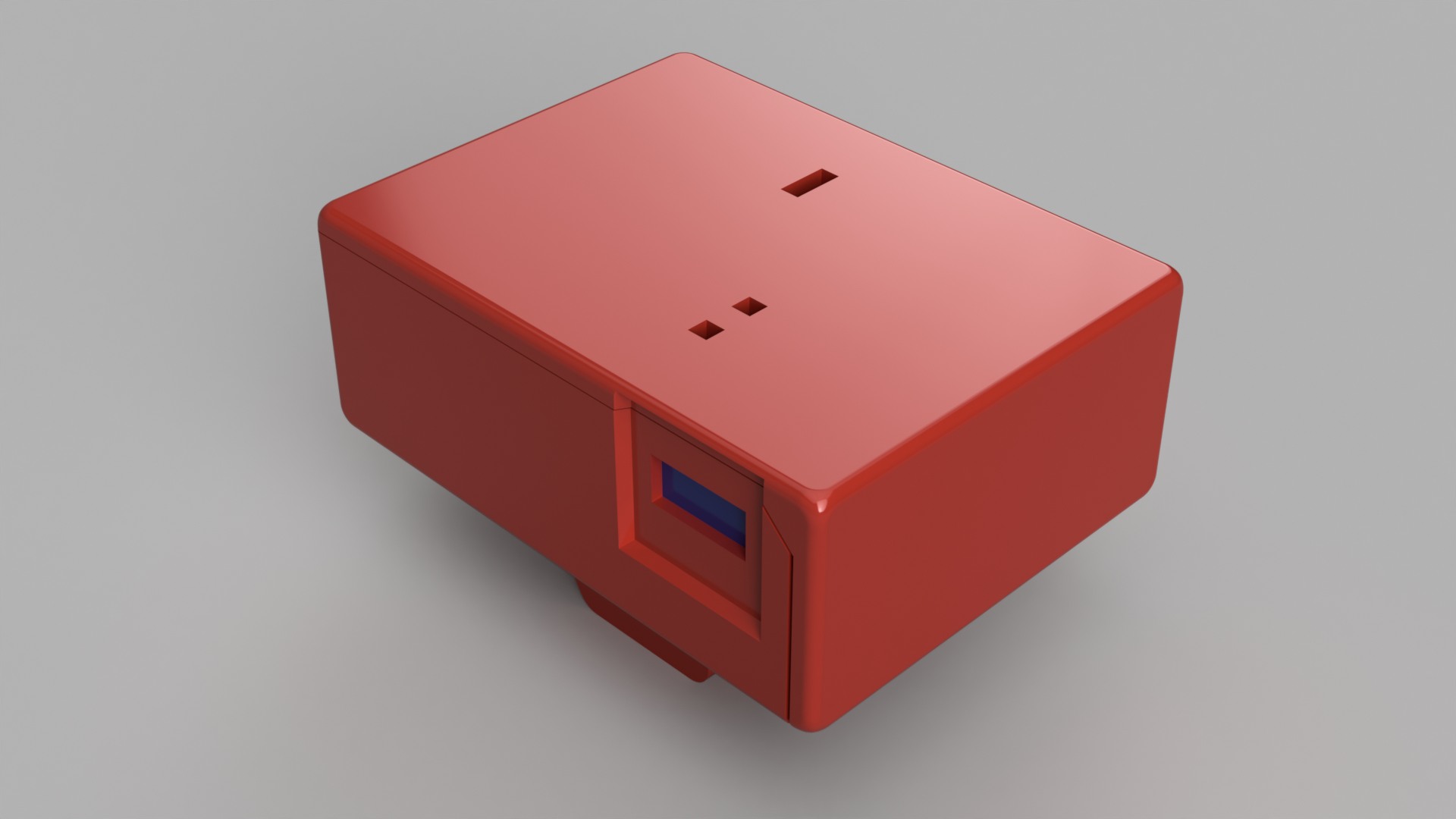
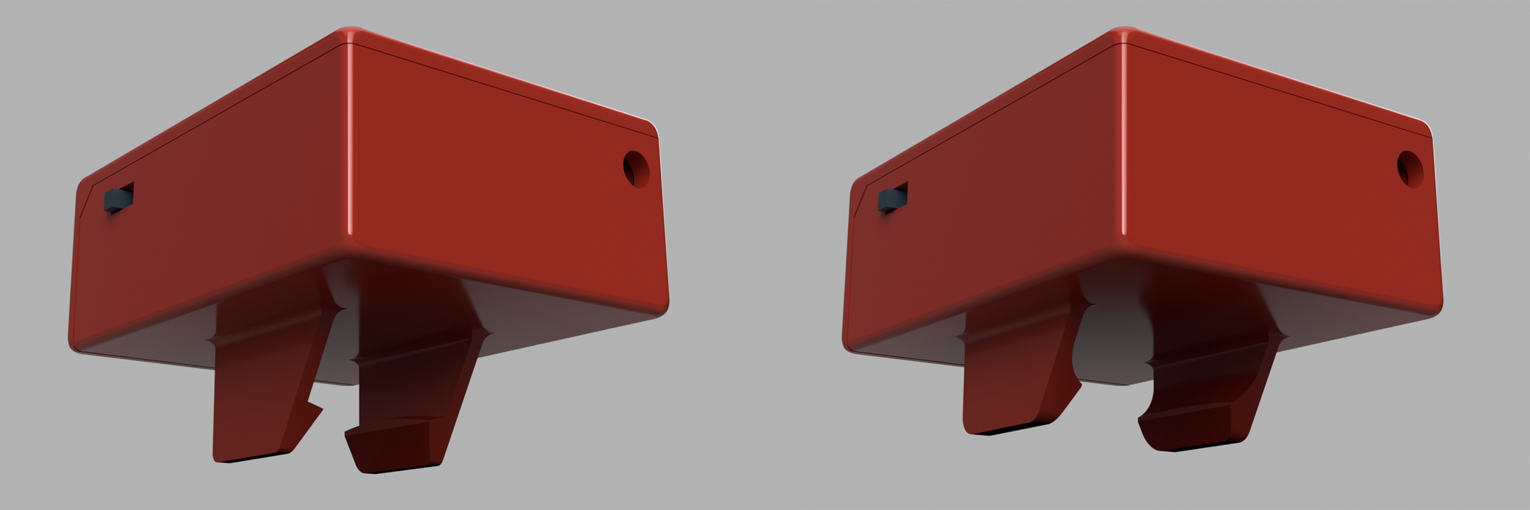
Casing Design Goals
The main design goals for the casing was to make it as compact as possible as well as providing a good fit to both Bose QC15 and QC25. We also wanted to have the micro-USB charger port towards the back, the power switch towards the front and the Bose cable entry on the underside of the casing. Lastly, we wanted to be able to see the LEDs on the PCBs.
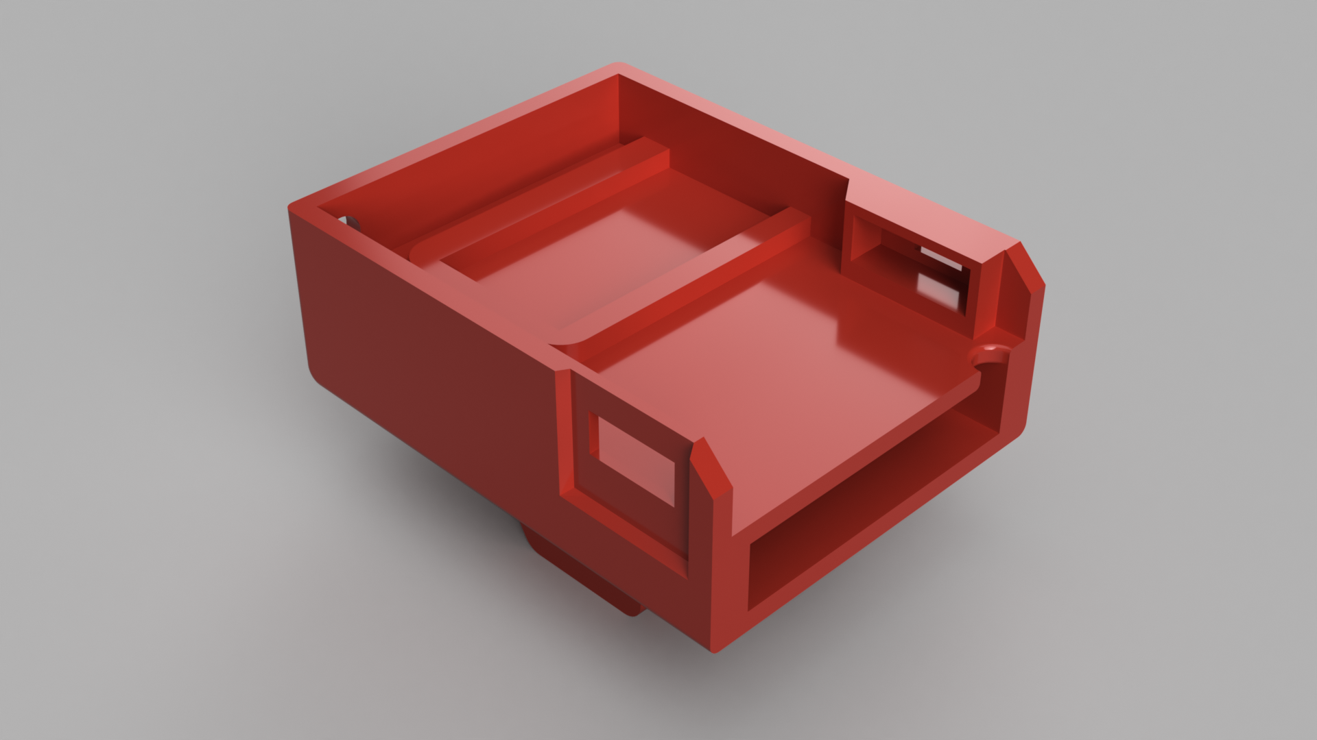
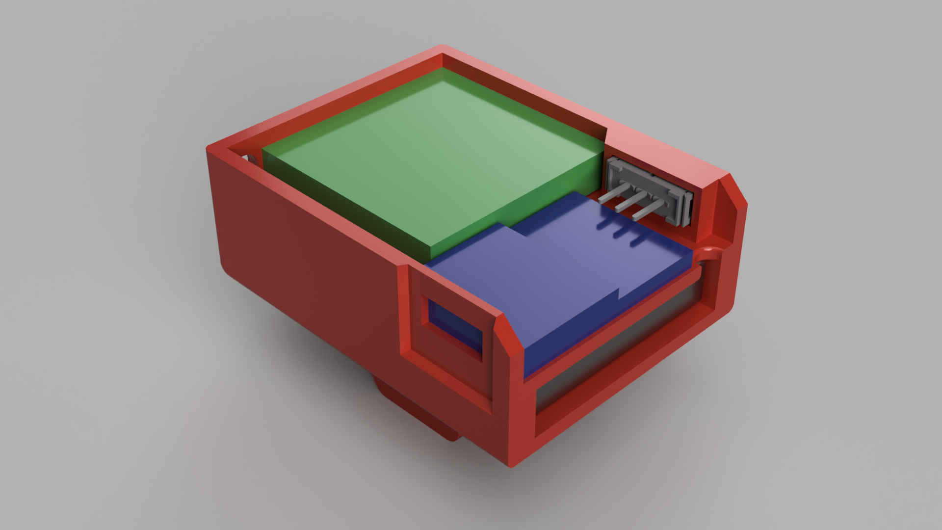
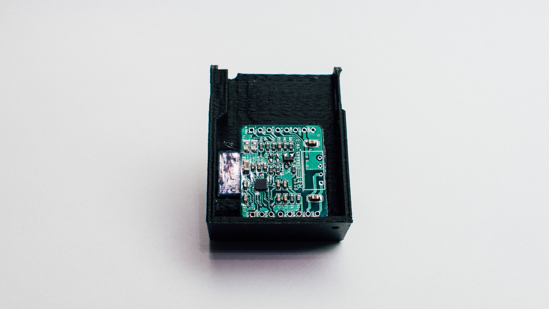
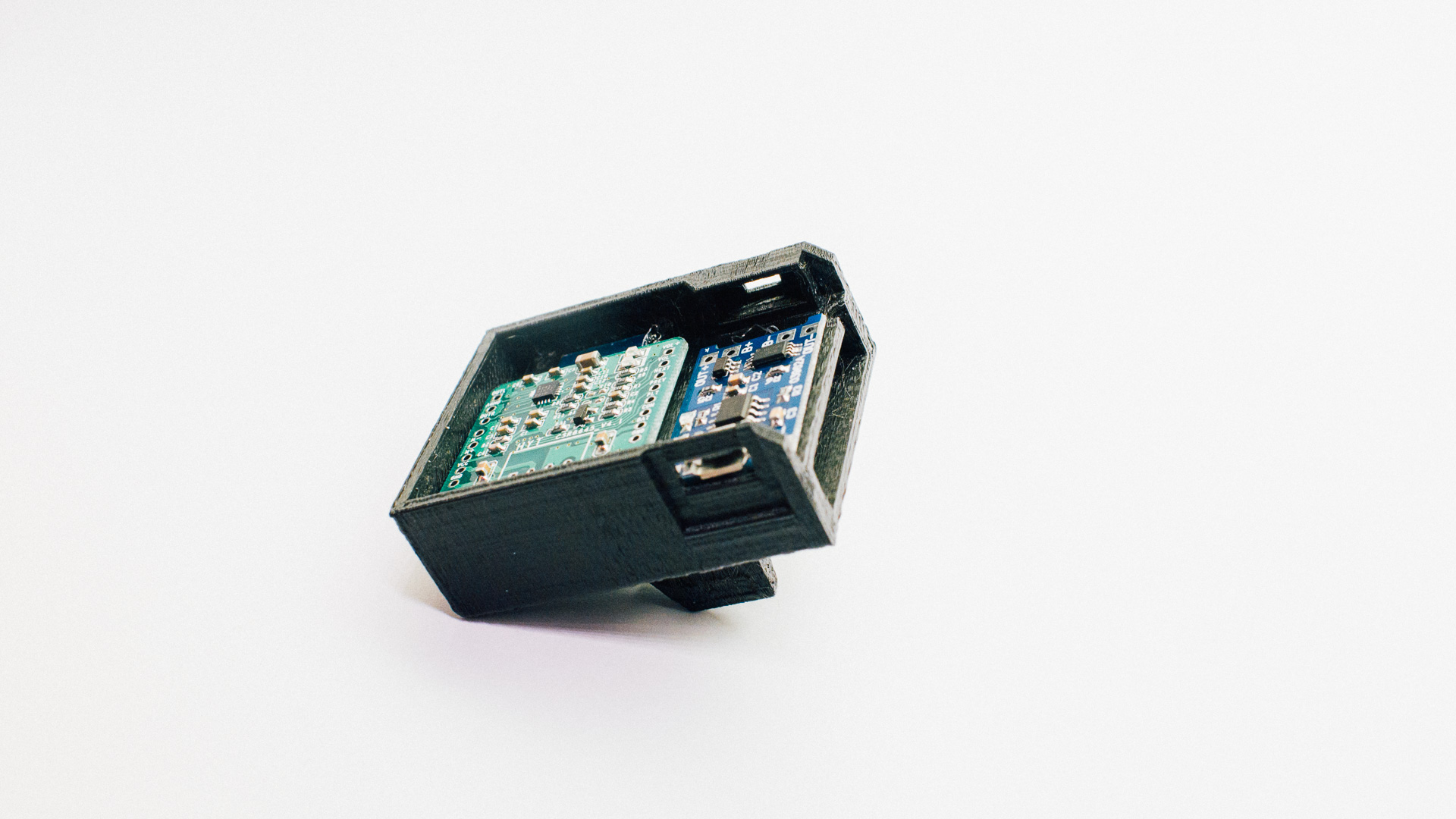
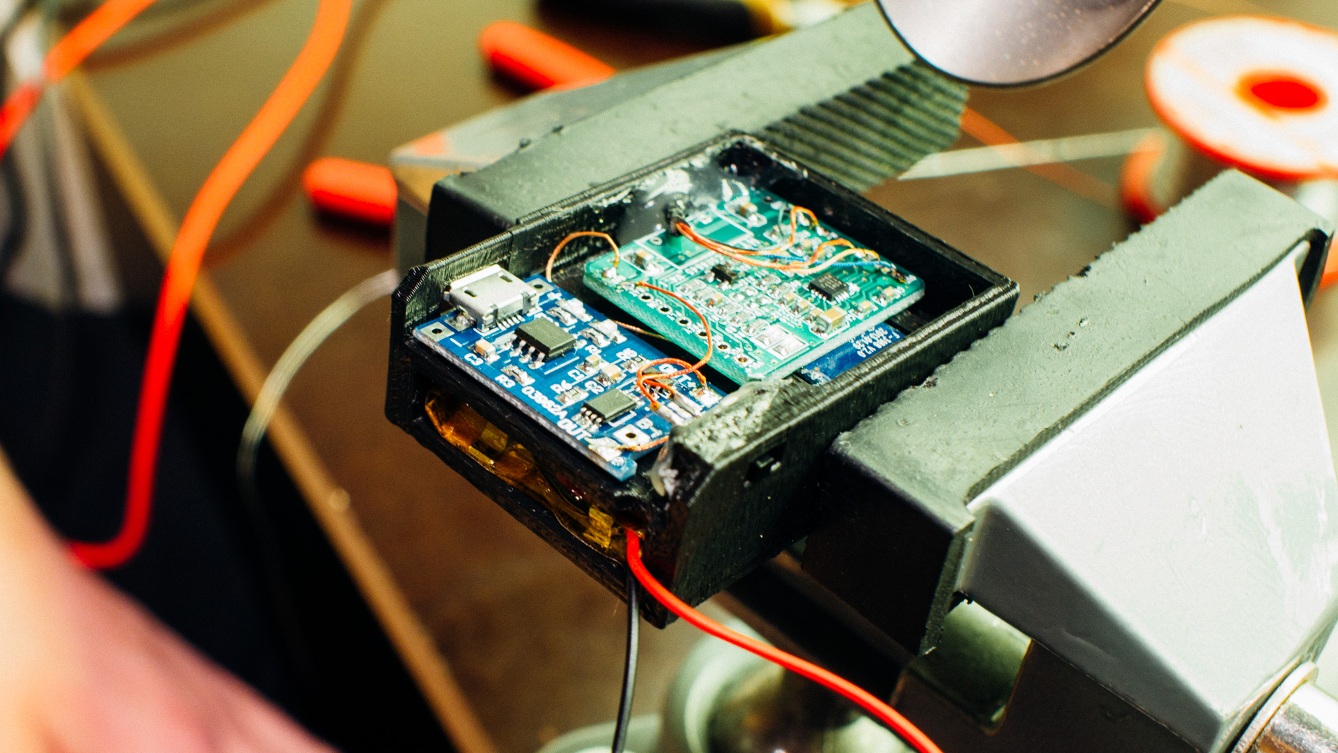
Casing Structure
The battery is in an own compartment on the inside of the “main room” where the two PCBs, power switch, USB port and cable entry reside.
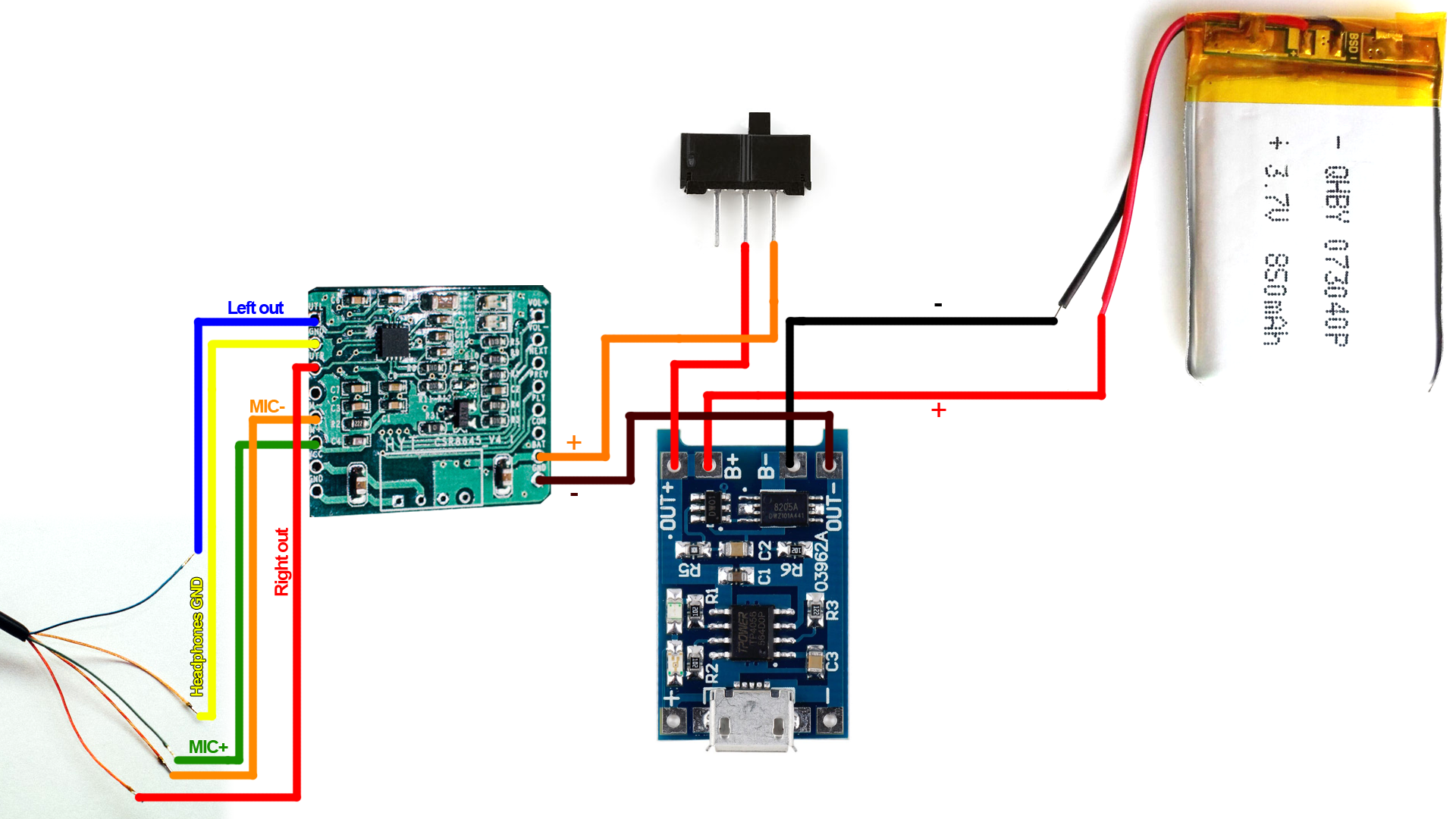
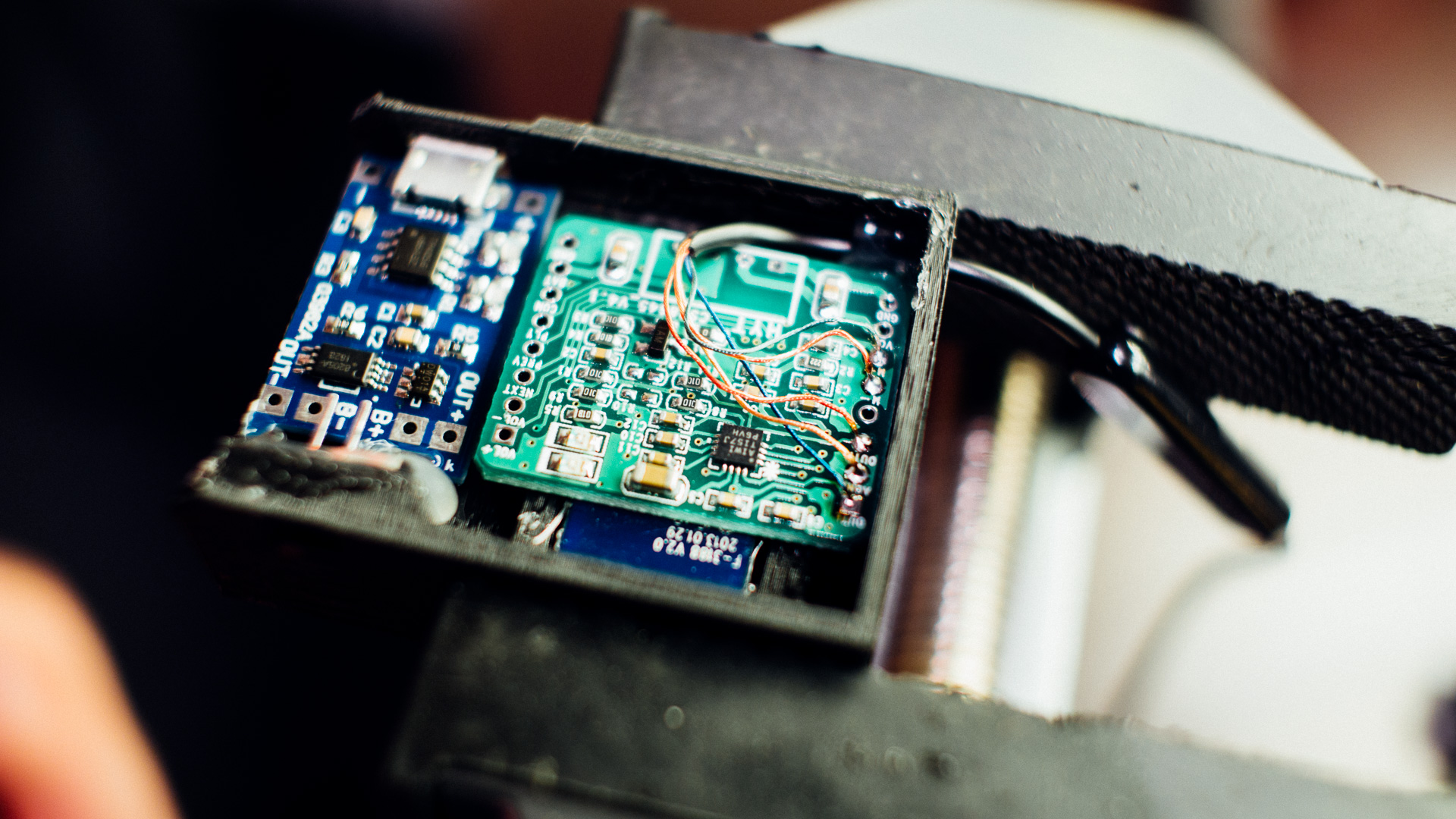
Electronics
The systems consists only of three main pieces. The Bluetooth module, battery and battery charger. When we designed this we wanted a long battery lifetime and therefore we selected a battery with 850mAh at 3.7V. In our testing the Bluetooth module have at least battery for one work week (8 hours a day, 5 days).
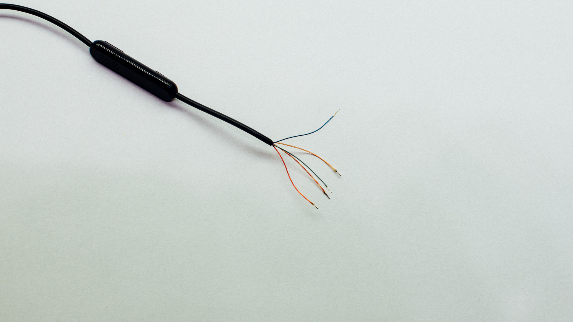
Our Bose headphone cables had the following color / pin out:
- Red: Right output
- Blue: Left ouput
- Brass: Headphones GND
- Green: MIC +
- Brass & Red: MIC –
Step-by-step Guide
Step 1: Get Everything Ready
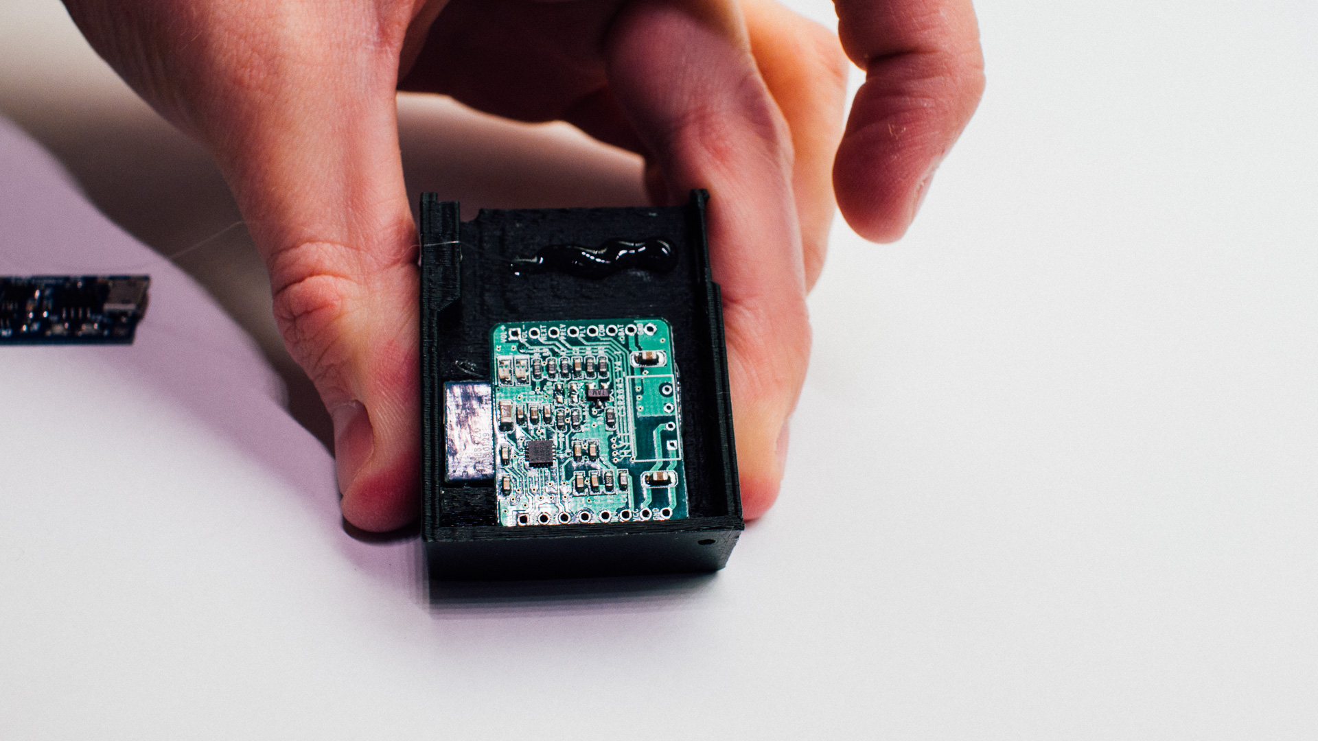
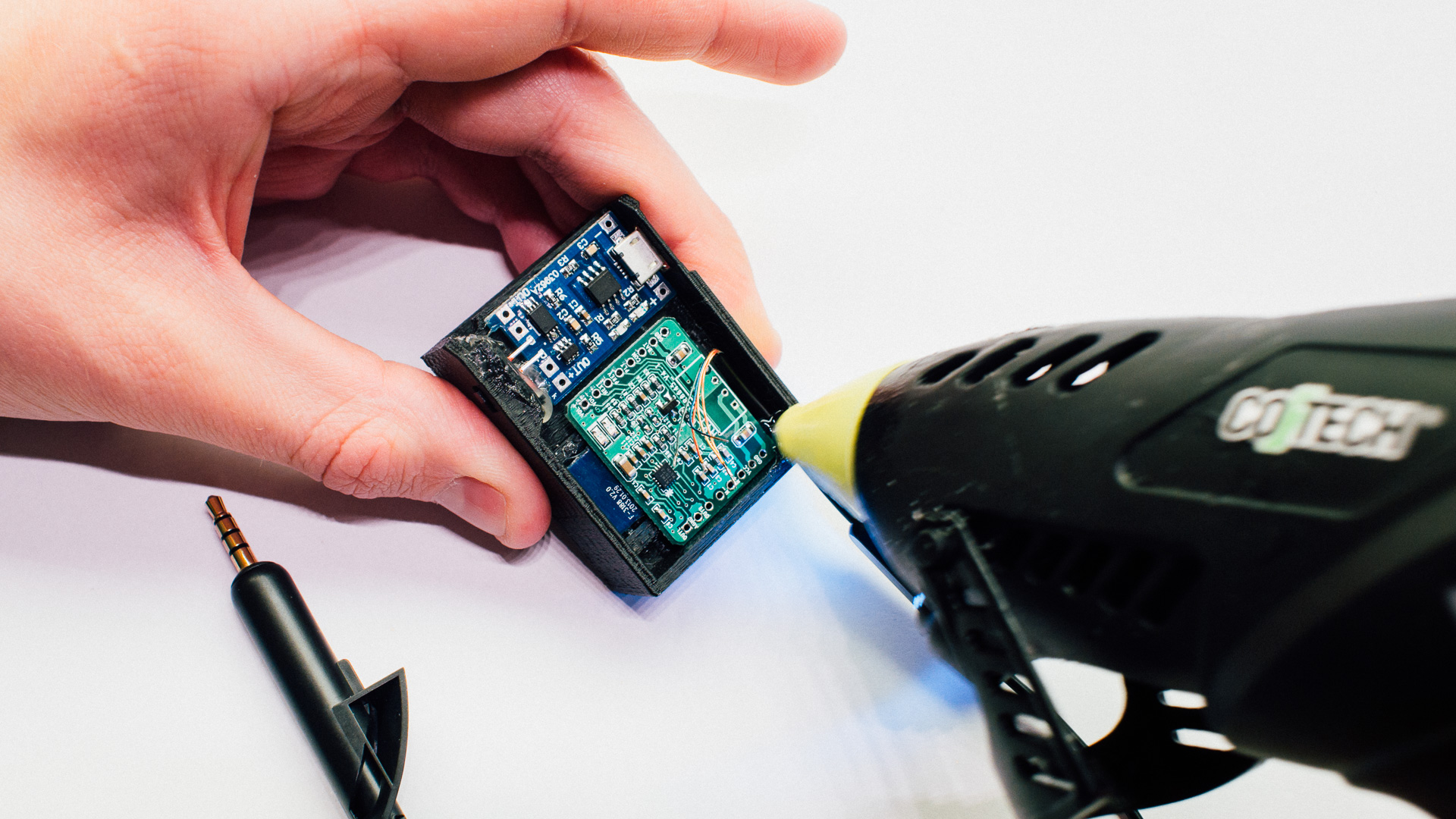
Step 2: Glue the Bluetooth Module to the Casing
We use common hot glue.
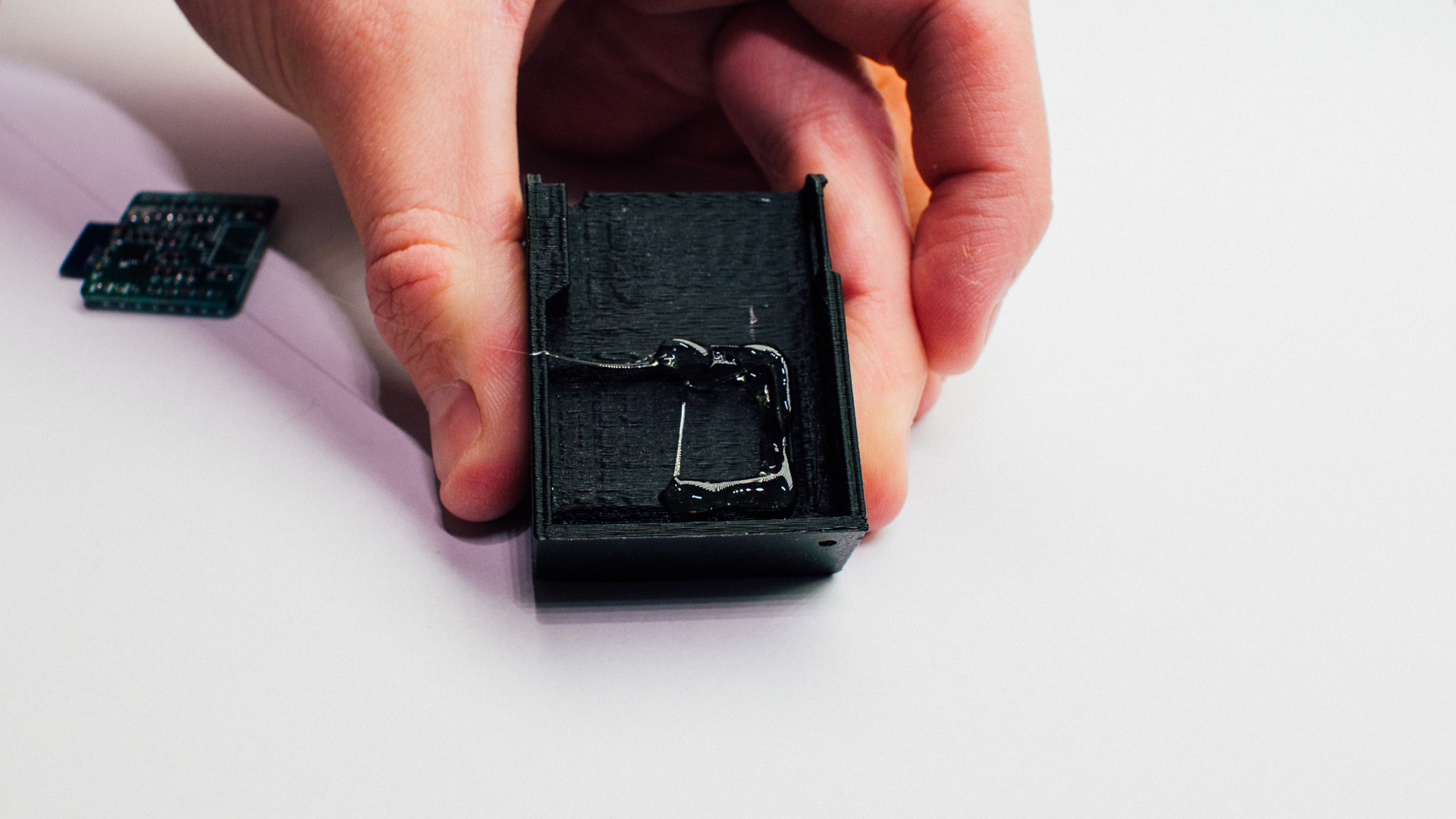
Step 3: Glue the Blue Charging Module to the Casing
Step 4: Glue the Switch to the Casing
Apply some hot glue to one of the large sides of the switch and slide it into its socket. Afterwards, apply glue around the back of the switch to keep it tightly fastened in the socket.
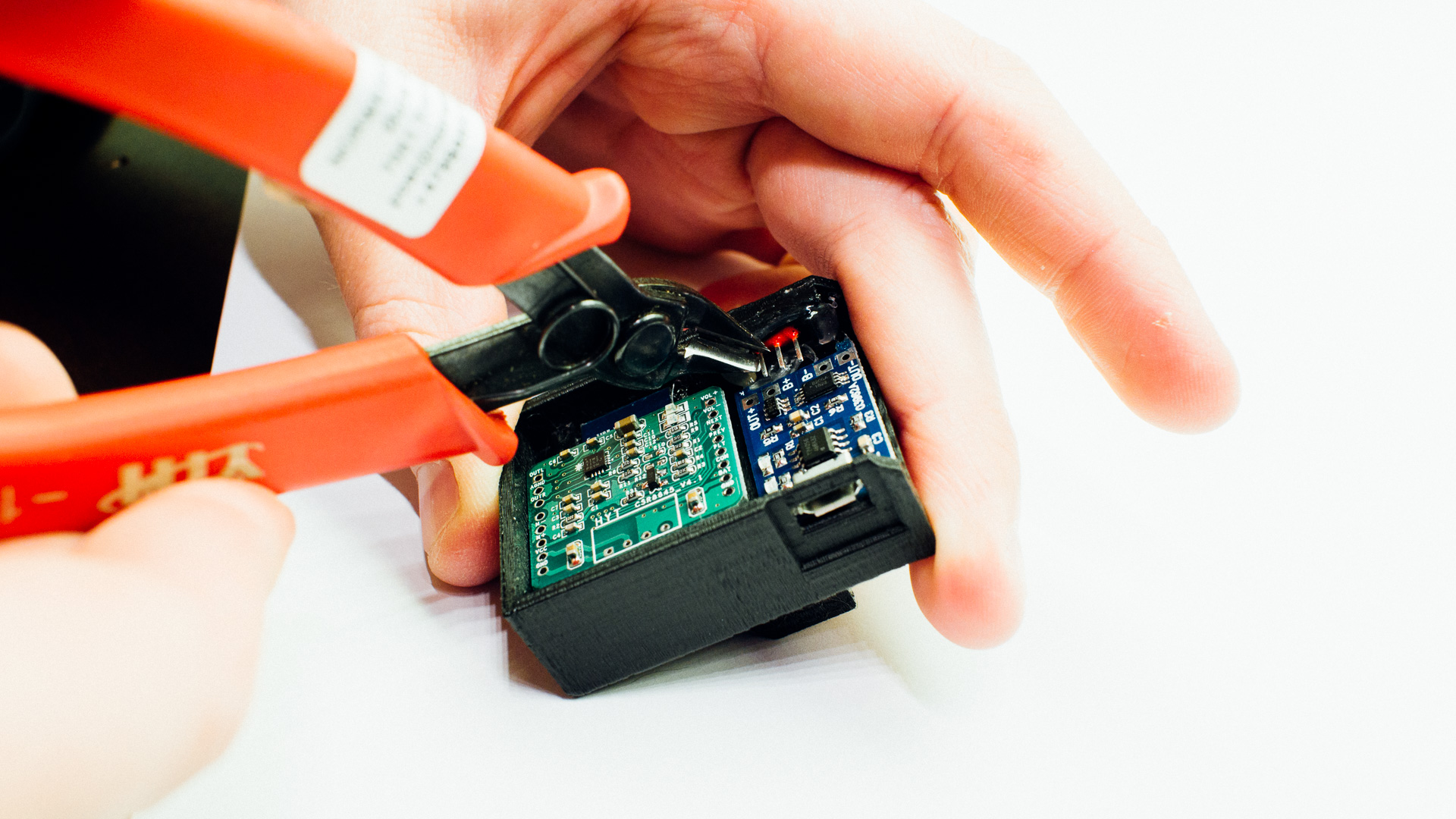
Step 5: Cut One of the Pins off the Switch
We don’t need all of the switch pins, and one is in the way, so remove that sucker.
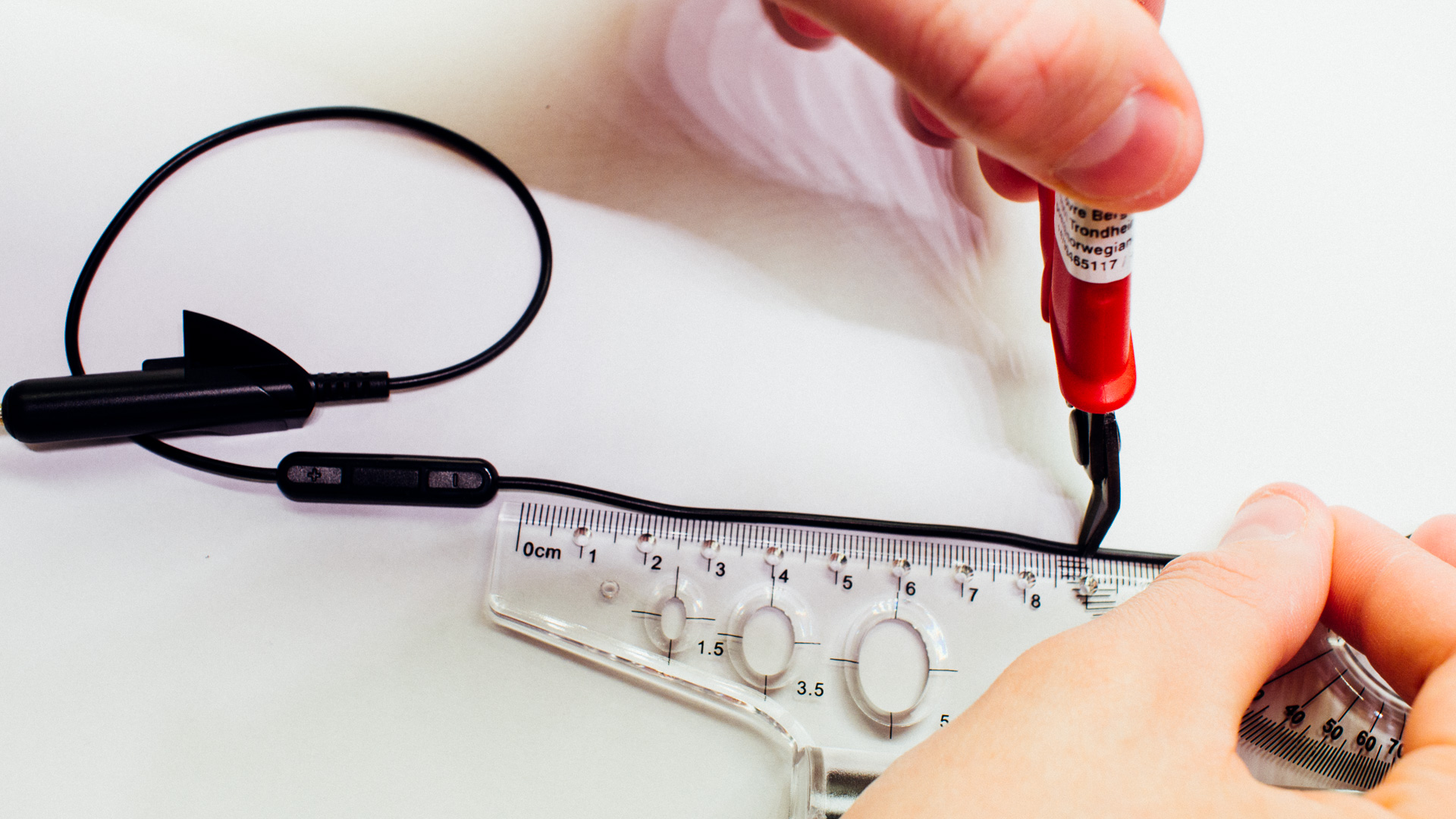
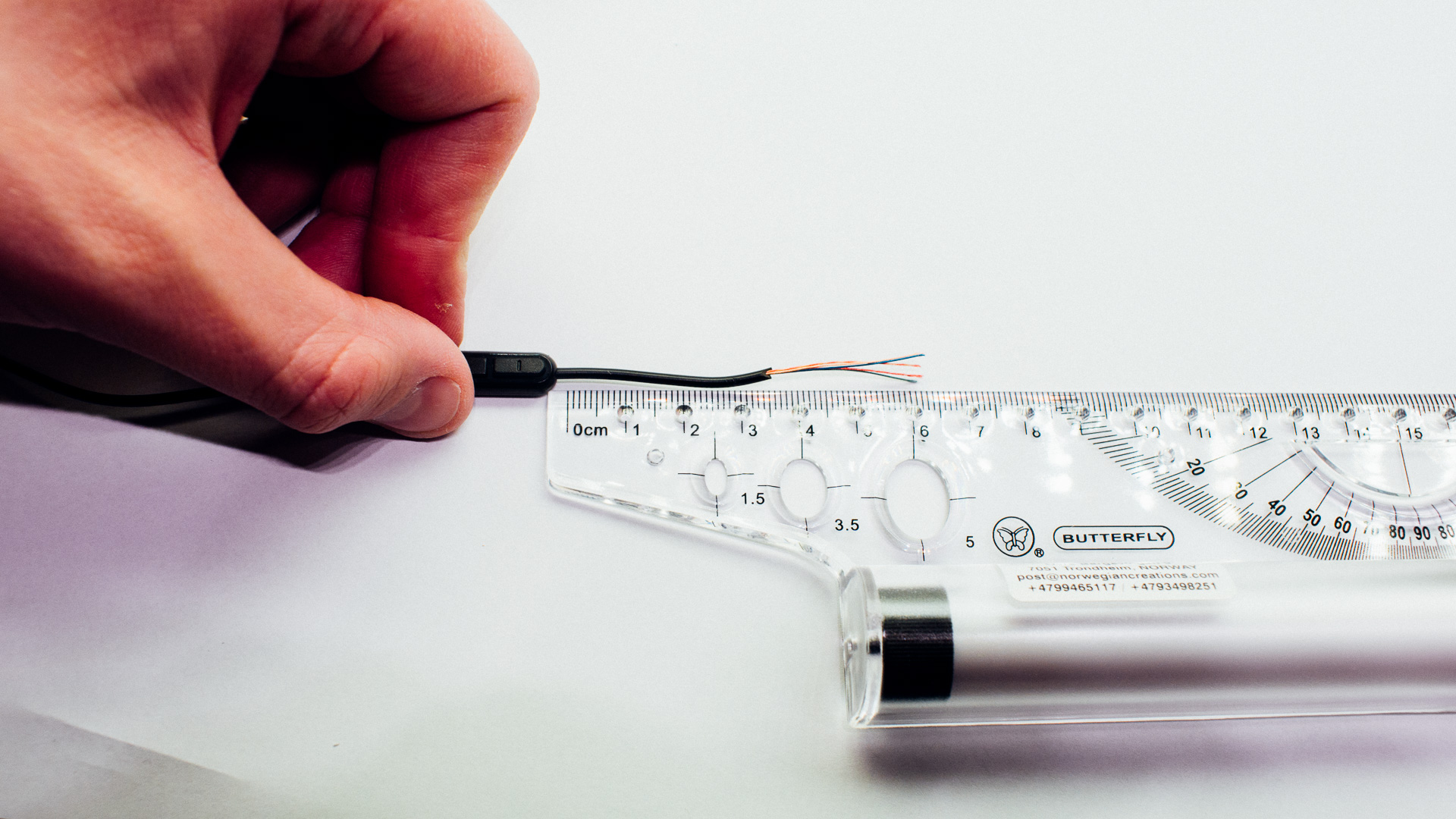
Step 6: Cut and Strip the Cable
Cut the cable to a suitable length. Keep in mind that the cord length between the plug and the cable buttons differ between the QC15 and the QC25 cables.
Step 7: Strip the Inner Wires and Tin Them
Use a lighter or sanding paper to strip the inner wires. Thereafter apply tin with the soldering iron.
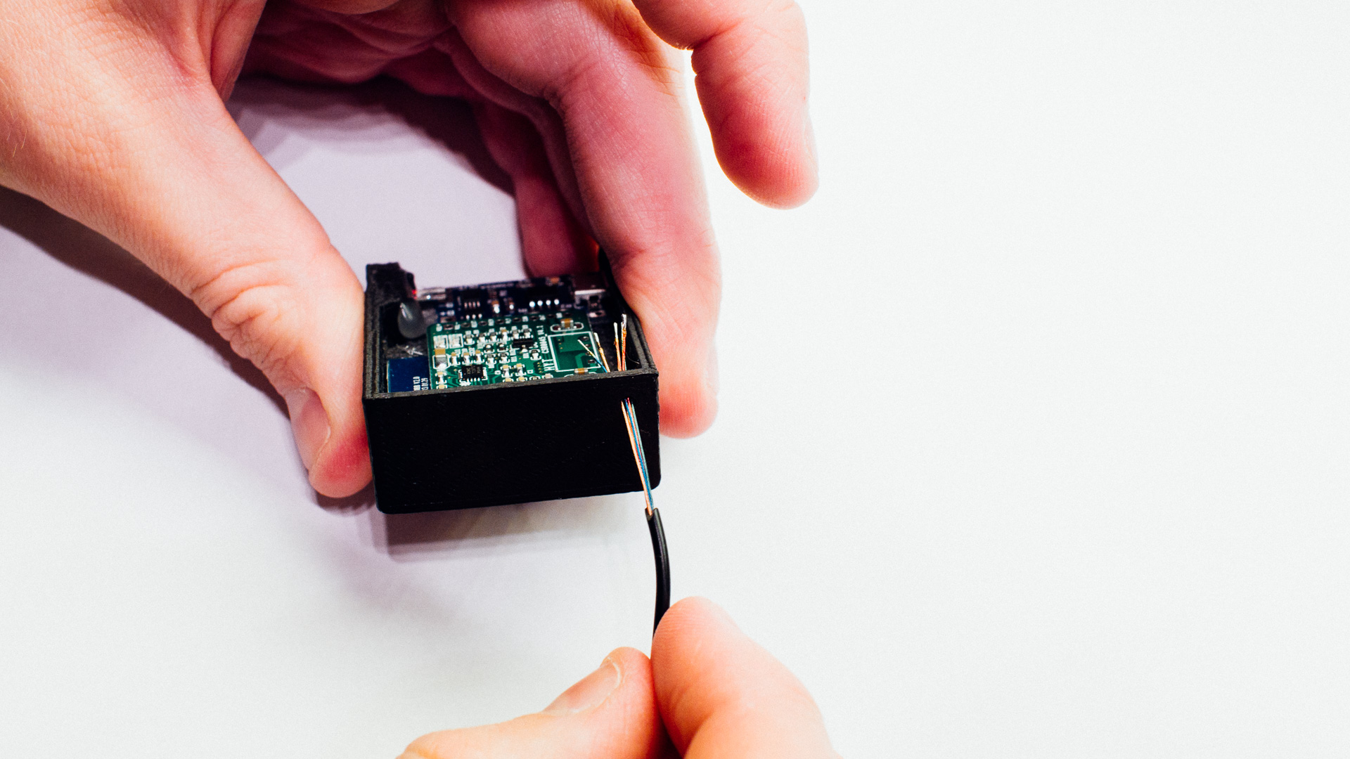
Step 8: Insert the Cable and Fasten It on the Inside
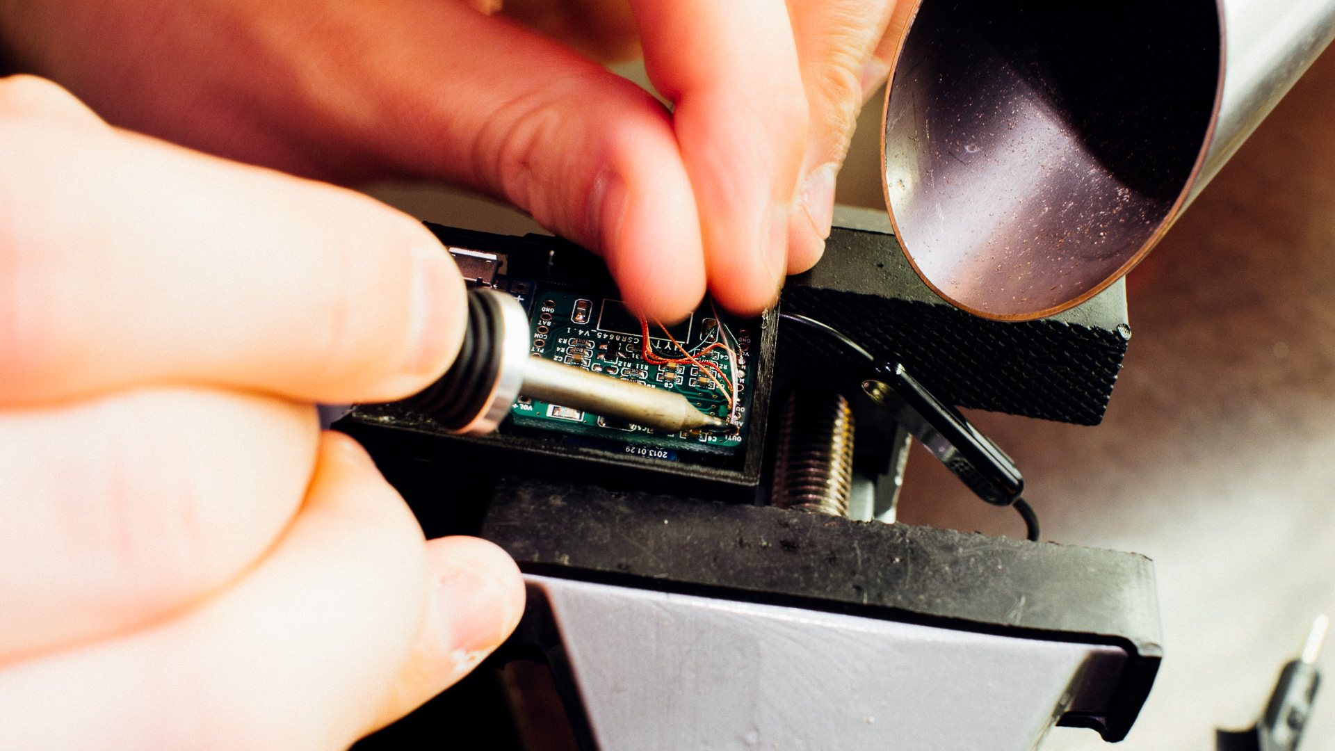
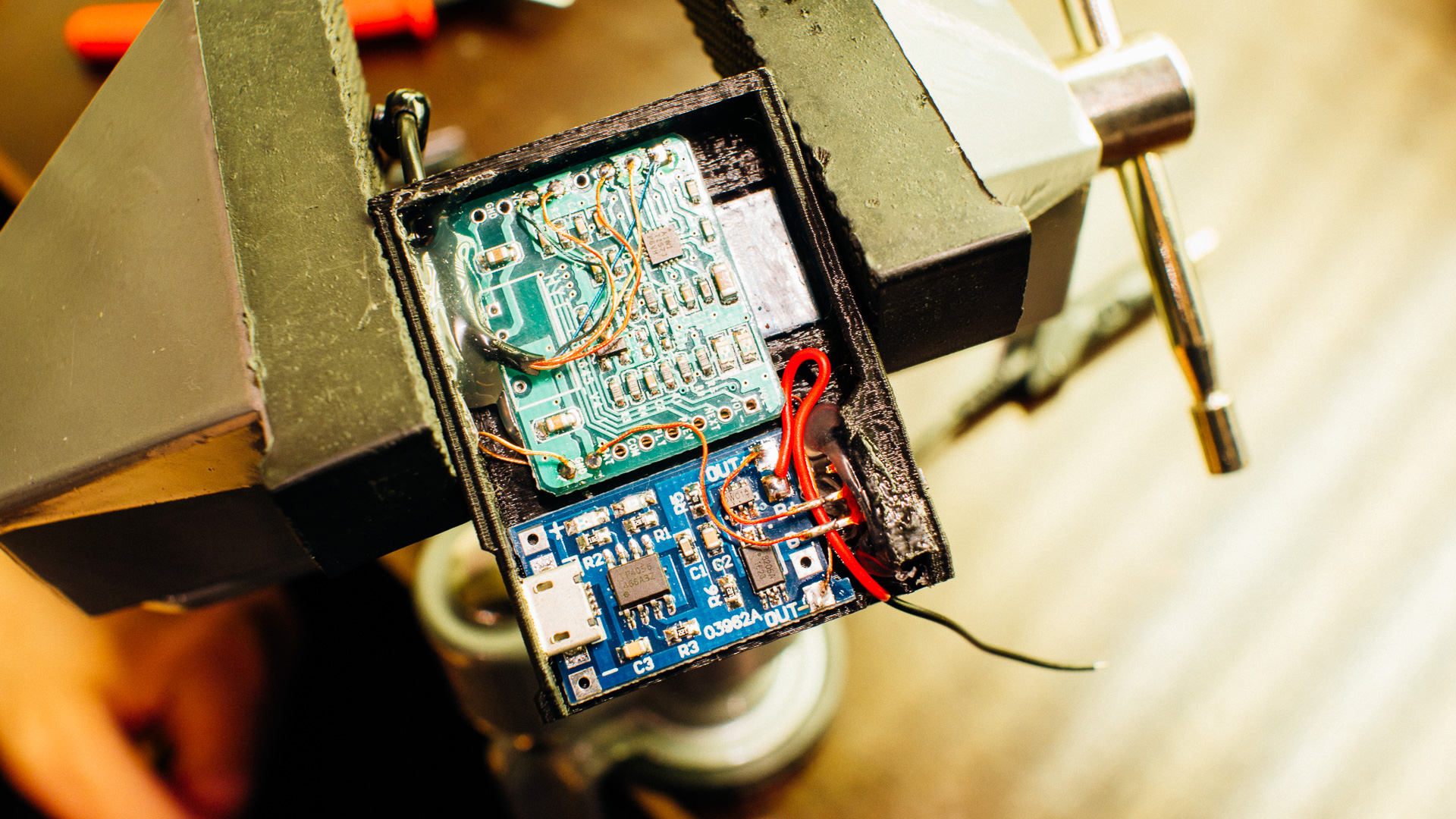
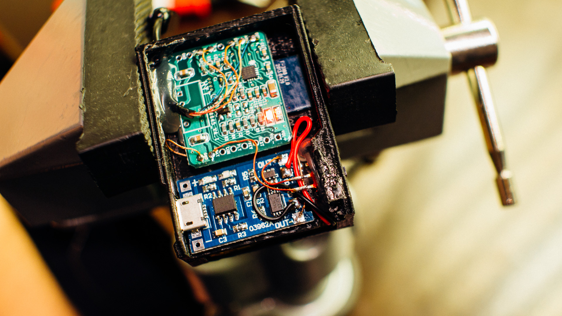
Step 9: Start Soldering
Follow the schematics above and solder.
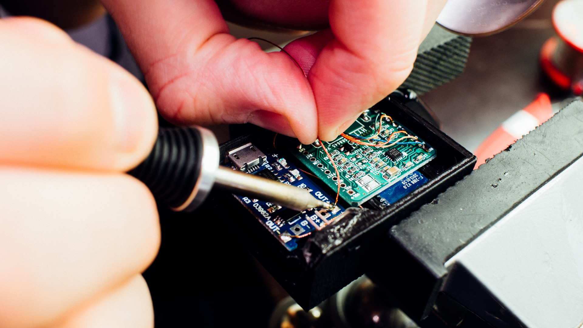
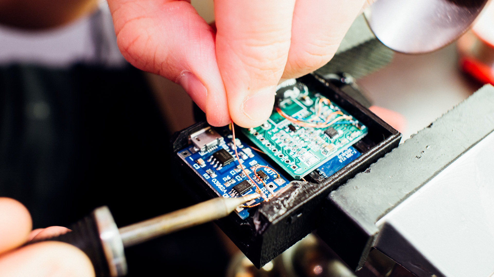
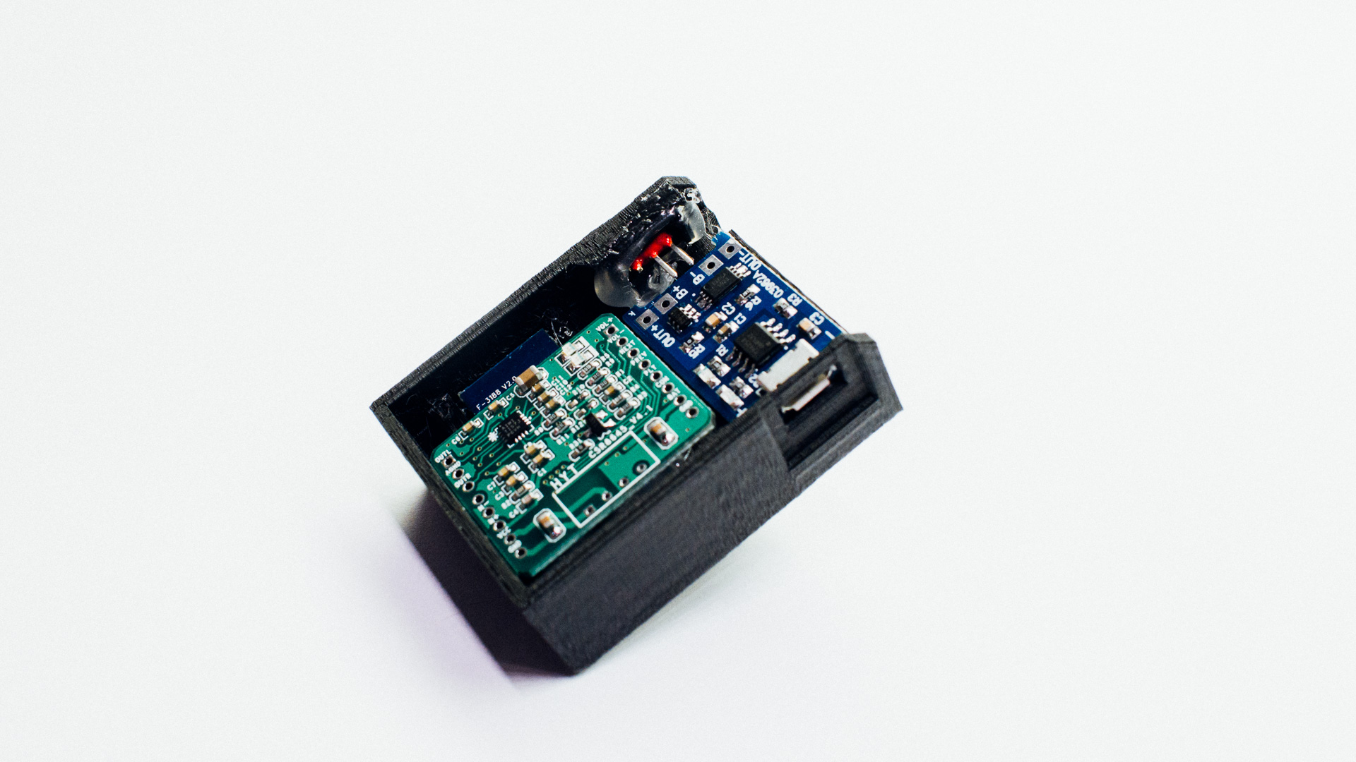
Step 10: Insert the Battery and Continue Soldering
Make sure the wires on the battery are on the correct side. Also be sure to solder the battery wires after everything else.
Step 11: Fasten the Lid
We used hot glue, but epoxy will probably work even better.
Step 12: Pair It to Your Device
Turn on the Bluetooth module and look for a Bluetooth device called CSR8645 on your computer, tablet or mobile phone. This is the one you need to connect to.
Wrapping Up
That’s it! Enjoy your new wireless Bose headset. 🙂
Feel free to comment on this post or send us a message if you have any questions about this project or if you have some pictures of your own built QC15/QC25 Bluetooth module!