In this post we will go through the inner workings of the Focus Box. What is creating the magic? You can read more about the background for this project in the blog post found here.

The Goal of the Internals
The job of “The internals” is mainly to create the sound:
- Read 4 analog channels (potentiometers) so the user can easily control Tone Frequency, Tone Volume, Noise Volume and Noise Low Pass Filter Frequency.
- Output analog sound in a headphone-compatible way.
- Have an appropriate input for neccessary power.
Enter Teensy
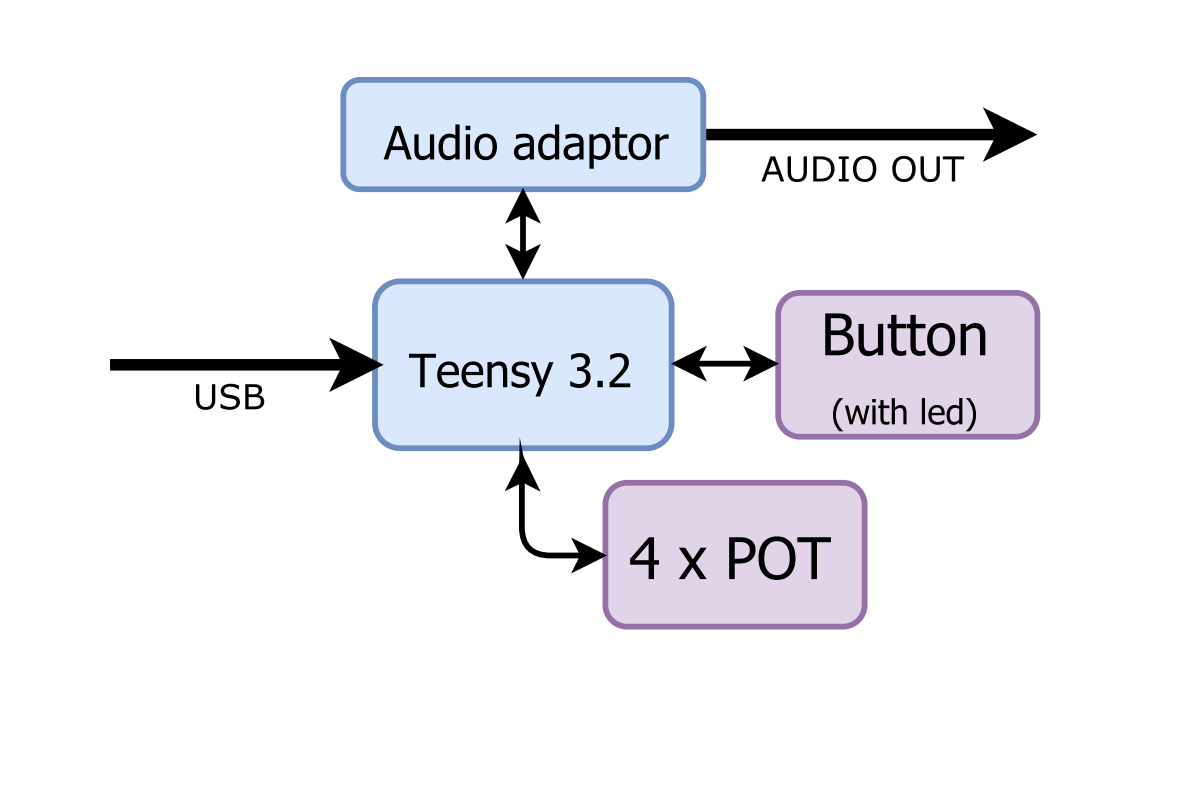
To handle this a Teensy 3.2 works great. Not just because we have them easily accessible, but also because it has a suitable audio addon for this job!
You can read more about the Teensy here, and the audio adaptor here.
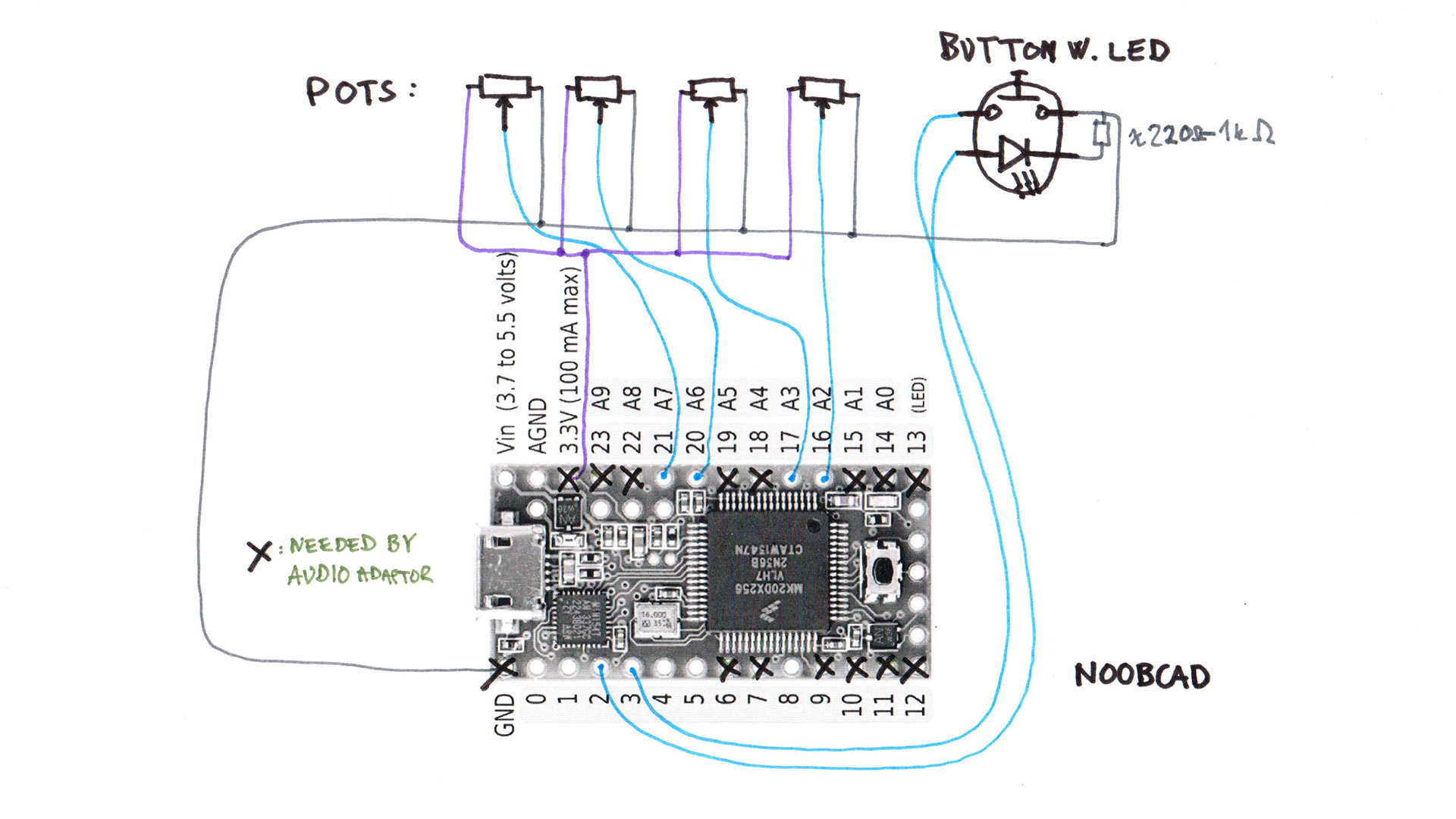
The potentiometers are just regular 10k linear and the button is a regular pushbutton with LED from here.
The linear potentiometers are going to get knobs like this.
In this “quick-and-dirty” napkin sketch you can see how the internals are wired up:
Audio generation
The total system has an internal flow like this:
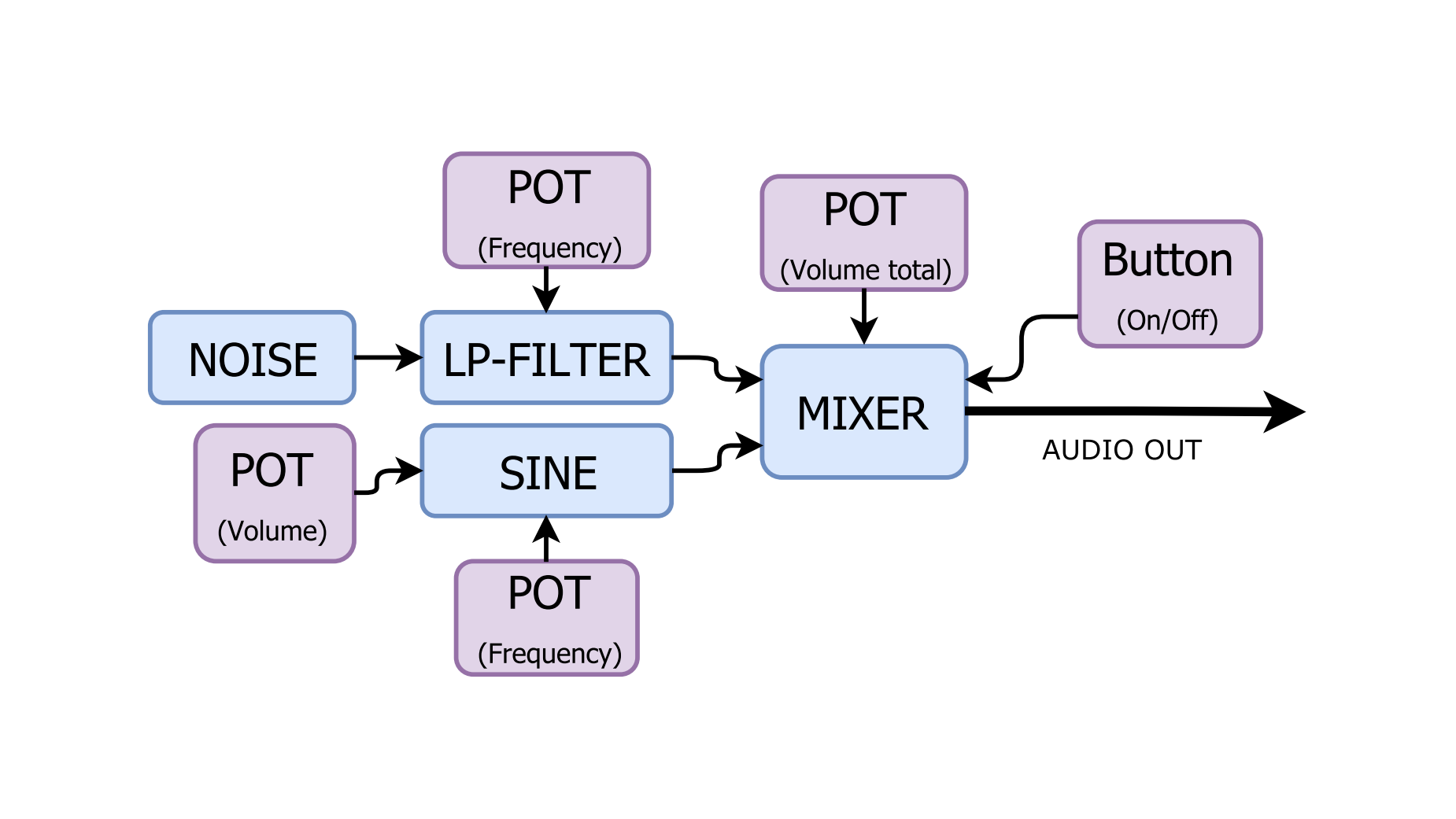
And the “sound path” is easy to implement using the teensy Audio Library:
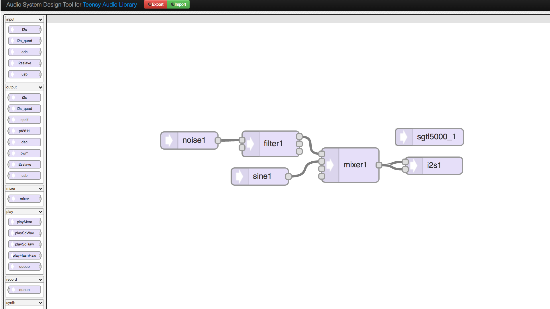
This is a screenshot from the “Audio System Design Tool For Teensy Audio Library“. It is a great tool for getting to know what possibilities you have with the library!
But remember that you have to code the user I/O and a lot of the audio module adjustments yourself!
What you get out from the graphical tool is line 10-22 in the code:
#include <TimeLib.h>
#include <Audio.h>
#include <Wire.h>
#include <SPI.h>
#include <SD.h>
#include <SerialFlash.h>
#include <Bounce2.h>
#include <EEPROM.h>

// GUItool: begin automatically generated code
AudioSynthNoiseWhite     noise1;         //xy=454,389
AudioSynthWaveformSine   sine1;          //xy=468,453
AudioFilterStateVariable filter1;        //xy=587,396
AudioMixer4              mixer1;         //xy=726,433
AudioOutputI2S           i2s1;           //xy=888,436
AudioConnection          patchCord1(noise1, 0, filter1, 0);
AudioConnection          patchCord2(sine1, 0, mixer1, 1);
AudioConnection          patchCord3(filter1, 0, mixer1, 0);
AudioConnection          patchCord4(mixer1, 0, i2s1, 0);
AudioConnection          patchCord5(mixer1, 0, i2s1, 1);
AudioControlSGTL5000     sgtl5000_1;     //xy=850,362
// GUItool: end automatically generated code

// pinout
#define PIN_POT_NOISE_FILTER_FREQ  16
#define PIN_POT_NOISE_VOL          17
#define PIN_POT_TONE_FREQ          20
#define PIN_POT_TONE_VOL           21
#define PIN_LEDBUT_SELECT           2
#define PIN_LEDBUT_LED              3

// GLOBAL variables
int NOISE_FILTER_FREQ   = 0;
int NOISE_VOL           = 0;
int TONE_FREQ           = 0;
int TONE_VOL            = 0;
int LEDBUT_SELECT       = 0;

int STATE = 0;

Bounce bouncer = Bounce();

///  HELPER FUNCTIONS ///
void led_on()
{
  digitalWrite(PIN_LEDBUT_LED, HIGH);
}

void led_off()
{
  digitalWrite(PIN_LEDBUT_LED, LOW);
}

// from http://playground.arduino.cc/Code/EEPROMReadWriteLong
// This function will write a 4 byte (32bit) long to the eeprom at
// the specified address to address + 3.
void EEPROMWritelong(int address, long value)
{
  //Decomposition from a long to 4 bytes by using bitshift.
  //One = Most significant -> Four = Least significant byte
  byte four = (value & 0xFF);
  byte three = ((value >> 8) & 0xFF);
  byte two = ((value >> 16) & 0xFF);
  byte one = ((value >> 24) & 0xFF);

  //Write the 4 bytes into the eeprom memory.
  EEPROM.write(address, four);
  EEPROM.write(address + 1, three);
  EEPROM.write(address + 2, two);
  EEPROM.write(address + 3, one);
}

// from http://playground.arduino.cc/Code/EEPROMReadWriteLong
//This function will return a 4 byte (32bit) long from the eeprom
//at the specified address to address + 3.
long EEPROMReadlong(long address)
{
  //Read the 4 bytes from the eeprom memory.
  long four = EEPROM.read(address);
  long three = EEPROM.read(address + 1);
  long two = EEPROM.read(address + 2);
  long one = EEPROM.read(address + 3);

  //Return the recomposed long by using bitshift.
  return ((four << 0) & 0xFF) + ((three << 8) & 0xFFFF) + ((two << 16) & 0xFFFFFF) + ((one << 24) & 0xFFFFFFFF);
}
/////////////////////////

void setup() {
  // button input and with arduino-bouncer
  pinMode(PIN_LEDBUT_SELECT, INPUT_PULLUP);
  bouncer.attach(PIN_LEDBUT_SELECT);
  bouncer.interval(5);

  // Led output
  pinMode(PIN_LEDBUT_LED, OUTPUT);

  Serial.begin(9600);

  // Set sine volume
  sine1.amplitude(1.0);

  // Set noise volume
  noise1.amplitude(1.0);

  AudioMemory(14);

  sgtl5000_1.enable();
  sgtl5000_1.volume(0.7);

  // Mute noise & sine volume
  mixer1.gain(0,0);
  mixer1.gain(1,0);

  //filter1 settings
  filter1.octaveControl(0);
  filter1.resonance(0.5);

  // average last 32 readings pr. reading
  analogReadAveraging(32);
}

void loop() {

  // Update the bouncer
  bouncer.update();

  // Set state
  if(bouncer.rose()){
    // turn on
    if(STATE == 0){
      STATE = 1;
      led_on();
      setTime(0); // reset timer
    }
    // turn off
    else{
      STATE = 0;
      led_off();

      // Mute noise volume
      mixer1.gain(0,0);

      // Mute sine volume
      mixer1.gain(1,0);

      EEPROMWritelong(0,EEPROMReadlong(0)+(long)now()); // store time used (now() is in [s])
      Serial.println(EEPROMReadlong(0)); // print time used [s]
    }
  }

  // If ON
  if(STATE == 1){
    // Read all POT inputs. NOT A GOOD WAY TO HANDLE USER INPUT!
    NOISE_FILTER_FREQ = analogRead(PIN_POT_NOISE_FILTER_FREQ);
    NOISE_VOL = analogRead(PIN_POT_NOISE_VOL);
    TONE_FREQ = analogRead(PIN_POT_TONE_FREQ);
    TONE_VOL = analogRead(PIN_POT_TONE_VOL);

    AudioNoInterrupts();

    // Adjust noise volume
    mixer1.gain(0,NOISE_VOL/100.0);

    // Adjust sine volume
    mixer1.gain(1,TONE_VOL/3000.0);

    // Adjust sine freq
    sine1.frequency(TONE_FREQ);

    // Adjust noise LP filter freq
    filter1.frequency(NOISE_FILTER_FREQ*1.5);

    AudioInterrupts();
  }
}
As you can see in the comments this have some “quick-and-dirty” solutions. But it works!
The most prominent one is the handling of the analog inputs. Here they are read as fast as possible and 32 readings are averaged to create a simple low pass filter. But a better solutions should be implemented!
That could be solved by a timer controlled module firing each e.g. 10 ms. In that module each of the analog inputs are read, and applied an appropriate fiter. E.G. a double EMA.
We did also implement an EEPROM storage feature: Each time the module is turned off it stores the total amount of time used (in seconds). This is also sent out over serial (the USB), making it possible for the user to see this time!
The unit you are reading about has in the moment of writing been used a total of 14433 seconds.
Next post
In the next post we will wrap up this short series with how we created the casing and the externals.