Introduction
In our office, we have a coffee maker capable of making large amounts of coffee. This is mostly a great thing, but not when the office is mostly empty due to summer vacation. Getting a cup of coffee turned into a game of chance, where you could end up with a sip of four hour old coffee. Things had to change.
We decided to augment our coffee maker with an indicator showing how old the coffee was. The machine has a LED which is turned on when new coffee is made, and off otherwise. This could be uses to detect when new coffee was brewed.
Electronics
We decided to base the system on the recently released BBC micro:bit, which is a small microcontroller board created as an educational tool in the UK. We had one laying around, and wanted to get to know it through a project. The micro:bit comes with a built-in LED display, two buttons and loads of GPIO pins. The only external components we needed was an LDR (Light dependant resistor) in addition to a normal resistor. The components were connected in a voltage divider circuit, connected to the PIN 0 on the micro:bit. As the name suggests, the circuit splits the supplied voltage between the LDR and the resistor (R1). When the LDR resistance is high, it will get a larger portion of the supply voltage. This portion is measured by using the analog input of the micro:bit.
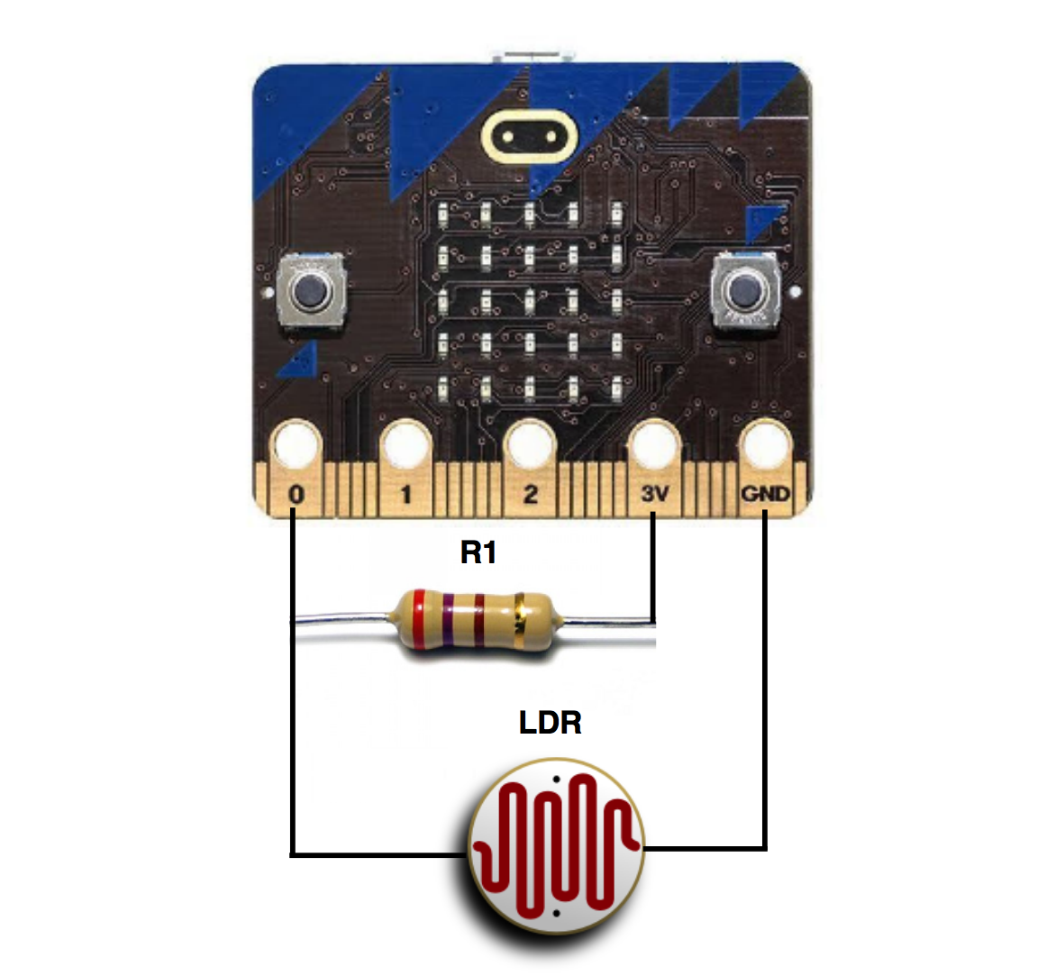
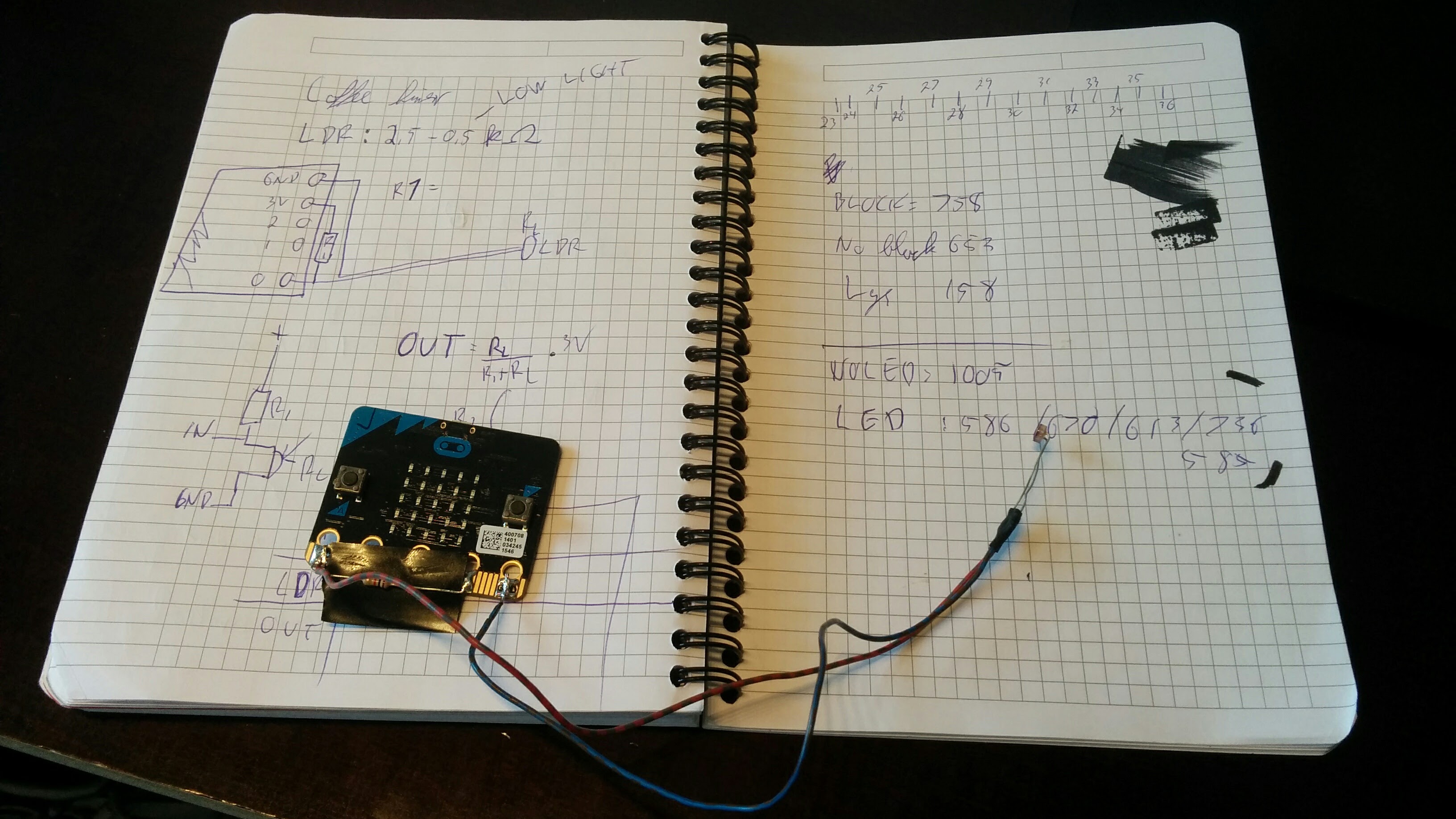
The resistance of the LDR varies between ~1 Ohm (bright light), and ~200 kOhm (no light). When testing the sensor on the coffee maker, it varied between ~2 Ohm (LED on), and ~10 Ohm (LED off). This is a small resistance difference, which forces us to use a small R1. This is because the measured voltage is based on how big resistance the LDR has compared to the total voltage divider. The equation for the measured voltage is Vin * LDR / (LDR+R1). If R1 is very large, the difference in the measured voltage will be very low. We need sufficient measuring resolution to distinguish the two states LED ON and LED OFF, with some changes in room lighting conditions. We chose an R1 of 220 Ohm. This gives us a decent voltage difference of 0.1 V on the analog input. However, having such a low R1 will cause the voltage divider circuit to draw a quite signification current of ~13 mA, which is a problem in low power systems. We will have USB power on our device, since the LED display already draws a lot of power.
Programming
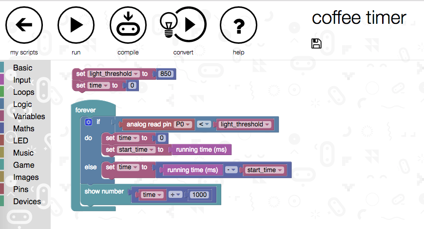
There exists a lot of ways to program the micro:bit, as presented on the board’s website. This blog on the bluetooth goes through them all, and even some additional programming options. We created the first test version of the coffee timer using the Microsoft block editor programming. The editor was surprisingly easy to use, and we quickly whipped up a very brute-force version of the functionality. When moving on, we used the ARM mBed online compiler to create our program. There we have access to the uBit C++ library provided by Lancaster University. The next level would be to scrap all the “high level” API’s, and program the on-board nRF51 Micro controller directly using the SDK provided by its manufacturer Nordic Semiconductor. We did not do this in this project, which led to some compromises being made. More on that in the next part of this series, where we discuss low power wireless using the micro:bit.
The first prototype
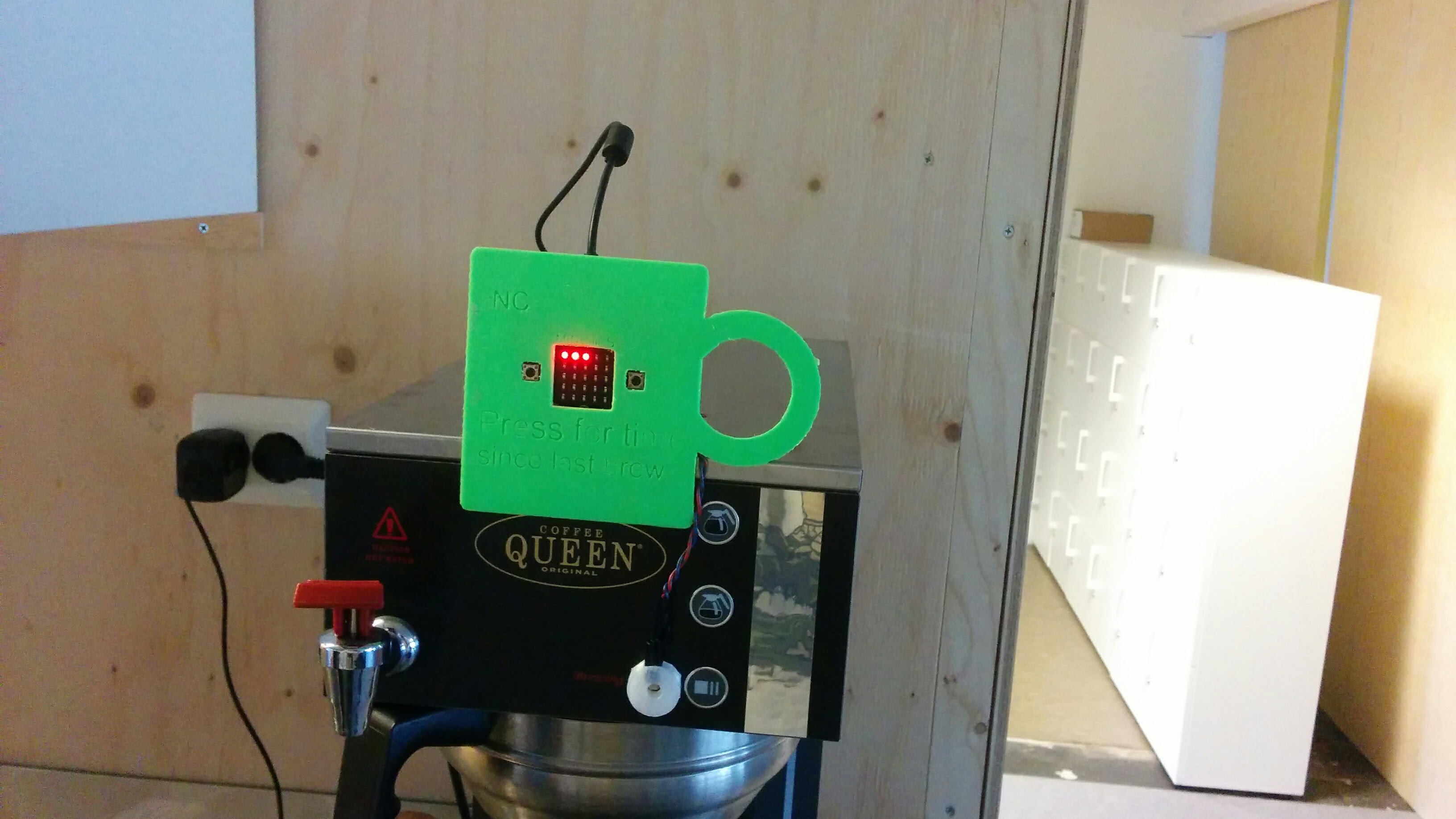
After the electronics and programming was tested and functional, we created an enclosure for the project. It was to be mounted on the coffee maker, and the sensor had to be mounted so that it could read the light of the coffee maker LED.
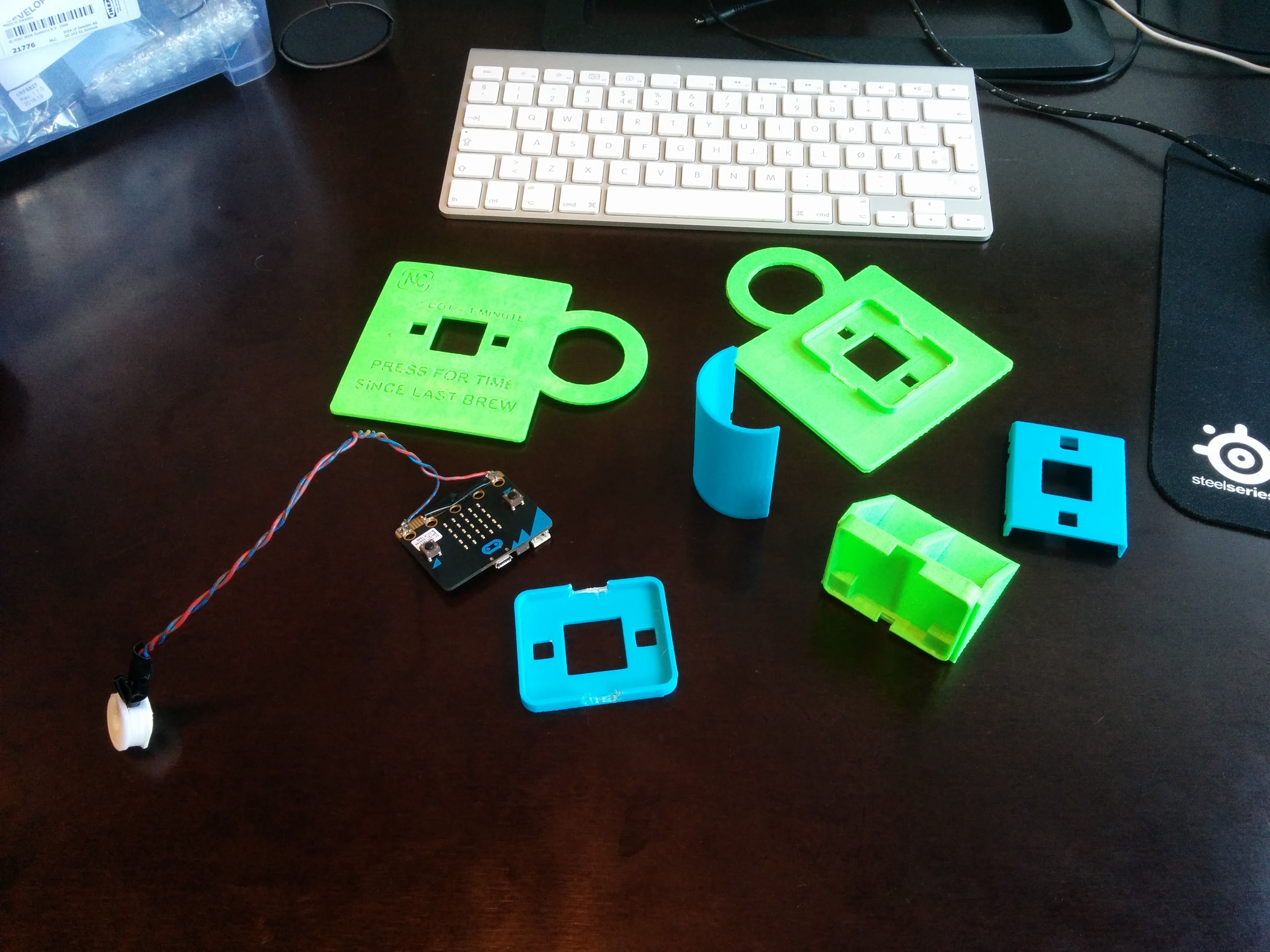
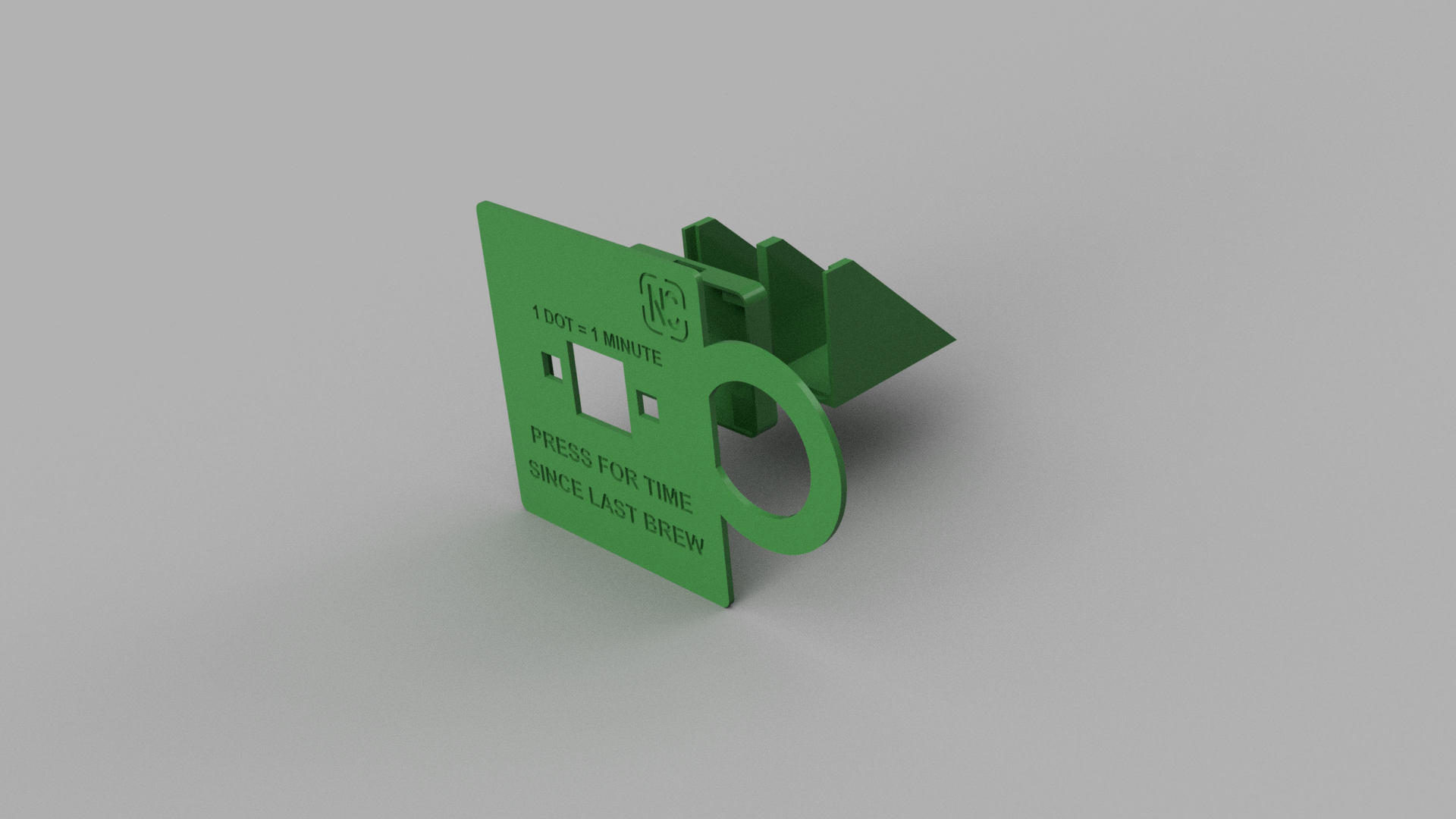
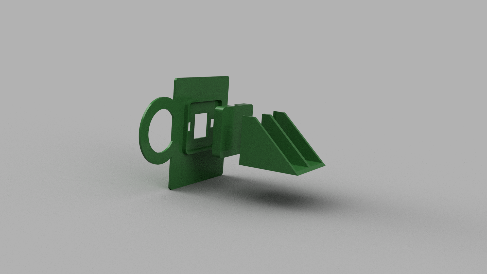
We created a bracket for the micro:bit, and then a front cover shaped as a coffee mug. In the first version, the resistor and soldering was not accounted for in the 3d-model. This made the front panel fit poorly, but it worked as a proof of concept.
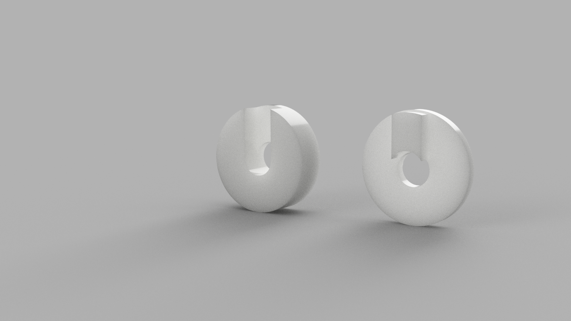
We created a small housing for the LDR. It has a hole in the middle where the LDR can sit and “view” the coffee maker LED. Is was printed in translucent PLA plastic, so that the LED light would be visible through the housing.
The designs were done in Autodesk Fusion 360, and the printing was done on a Type A 3d-printer.
The next step
This first post about the coffee timer project has shown a quick and dirty first edition. It does a good job at displaying the time, but the finish and construction is lacking. In the next posts, we will describe how we created a better version, which even includes wireless broadcasting of the coffee information.