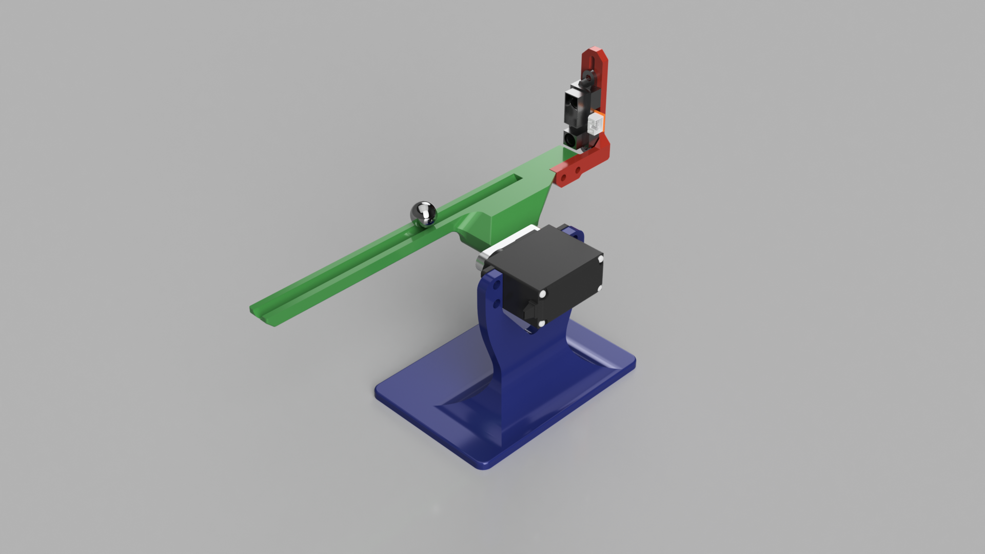
We got an idea of this small project which will be used as a platform to implement PID and other forms of motion control. Here’s an overview of how we’re envisioning the project.
UPDATE Oct. 31st 2016: we have added .stl files in the bottom of this post such that you can print this yourself!
The Plan
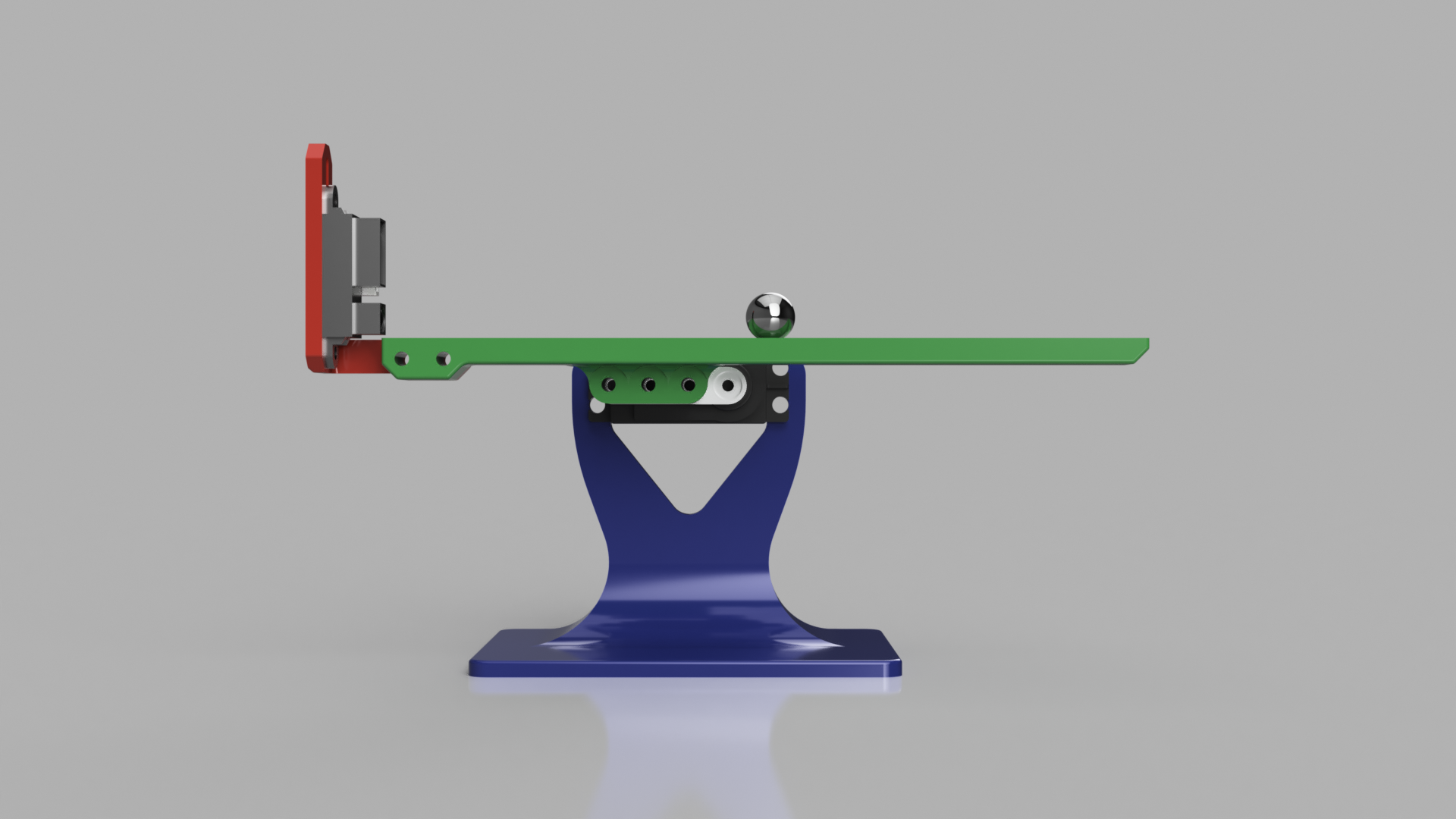
Balancing a ball on a platform like this is really cool. We wanted to do something similar, but a bit more simple. So we removed one dimension and approached it like a hanging seesaw where we’ll balance a ball in one dimension along a “gutter”.
Actuation
To actuate the seesaw we ended up using a single RC servo. We thought about using two servos with rods up to each end of the gutter, but a single servo in the center rotational axis makes things much simpler. The components carried by the servo are so light that weight won’t be an issue.
A drawback with this method is the servo resolution which might not be sufficient for properly balancing the ball, but in that case it will be interesting to see how the controller will compensate for lack of resolution. A possible upgrade can be to use a stepper motor with microstepping instead of a servo to acheive a greater resolution.
Sensor
To sense the position of the ball we chose to use a distance sensor. There are quite a few to choose from. IR-sensors have usually shorter range with a narrower field of view than ultrasonic sensors. These properties are desirable for this application, so we went infrared. If it works in practice remains to be seen.
Control
A standard Arduino will be used to control the seesaw. The Arduino will read the sensor data, run the PID-controller and control the servo. We will also use it to receive realtime reference values from a potentiometer.

Mechanical
The seesaw will have four mechanical components where three will be 3D printed: one base to attach the servo to, one aluminium servo arm, one main gutter-part and one sensor bracket which will be fastened to the gutter. We also have the ball, of course.
The Parts
Here’s an overview of all the main parts and components we plan to use in this project.
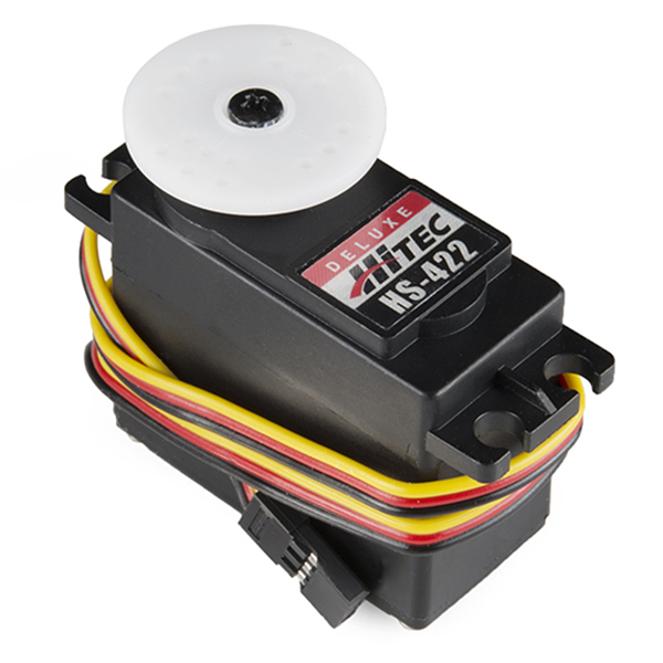
Hitec HS-422 Servo
A cheap, bog standard RC servo which fits a servo arm we want to use.
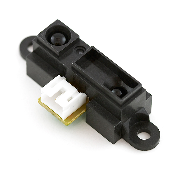
Sharp GP2Y0A41SK0F IR Distance Sensor
This particular distance sensor has a range of 4-30 cm and outputs a (non-linear) voltage based on the distance to an object in front of the emitter. A rough linearization will be done in software. One element of uncertainty is the field of view, which is not specfied in the datasheet. Hopefully it’s sufficiently narrow. One of these is neat to have as well.
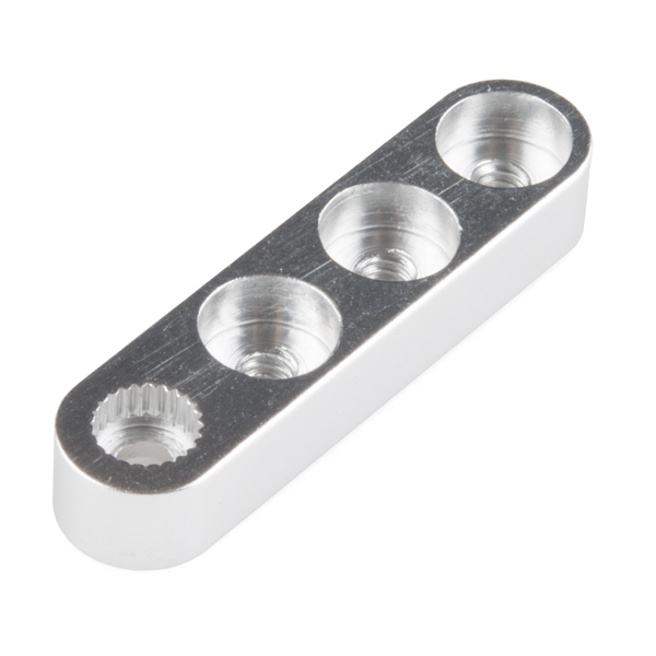
Aluminium Servo Arm
We’ll use one of these to attach the gutter to the servo. These are much more sturdy than the horns that come with the RC servos and they also have three threaded M3 holes for easier mounting.
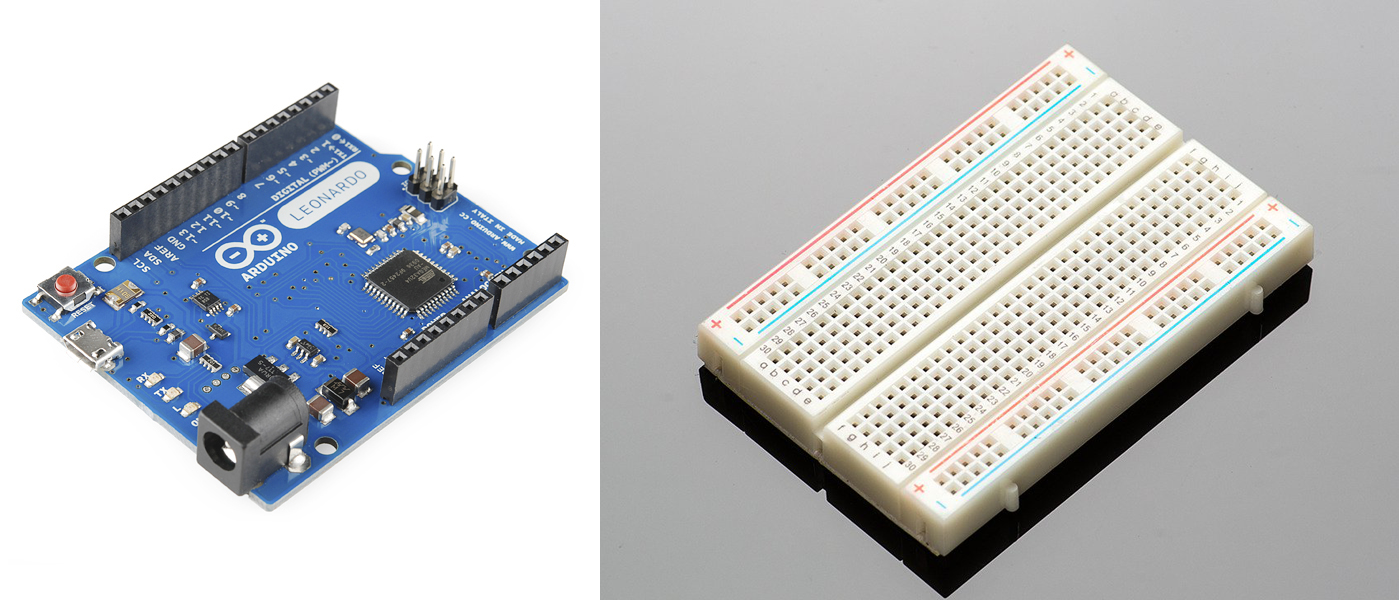
Arduino Leonardo with a Breadboard
Any Arduino or other small computer would’ve done the job. A potentiometer will be used to set either position or speed of the ball. The 10-bit ADC will ensure a sensor resolution of around 0.2 mm if the analog voltage from the sensor is completely continous and linear (which isn’t the case).
Steel Ball
The ball we’re going to use is a 12 mm steel ball used in these omni-directional wheels. Again, just something we have lying around.
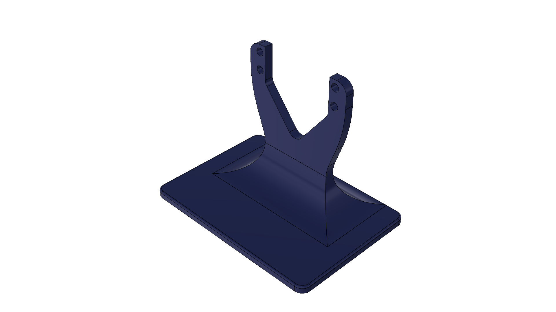
Base
The base is a simple platform to keep everything steady on the table as well as serve as a servo bracket.
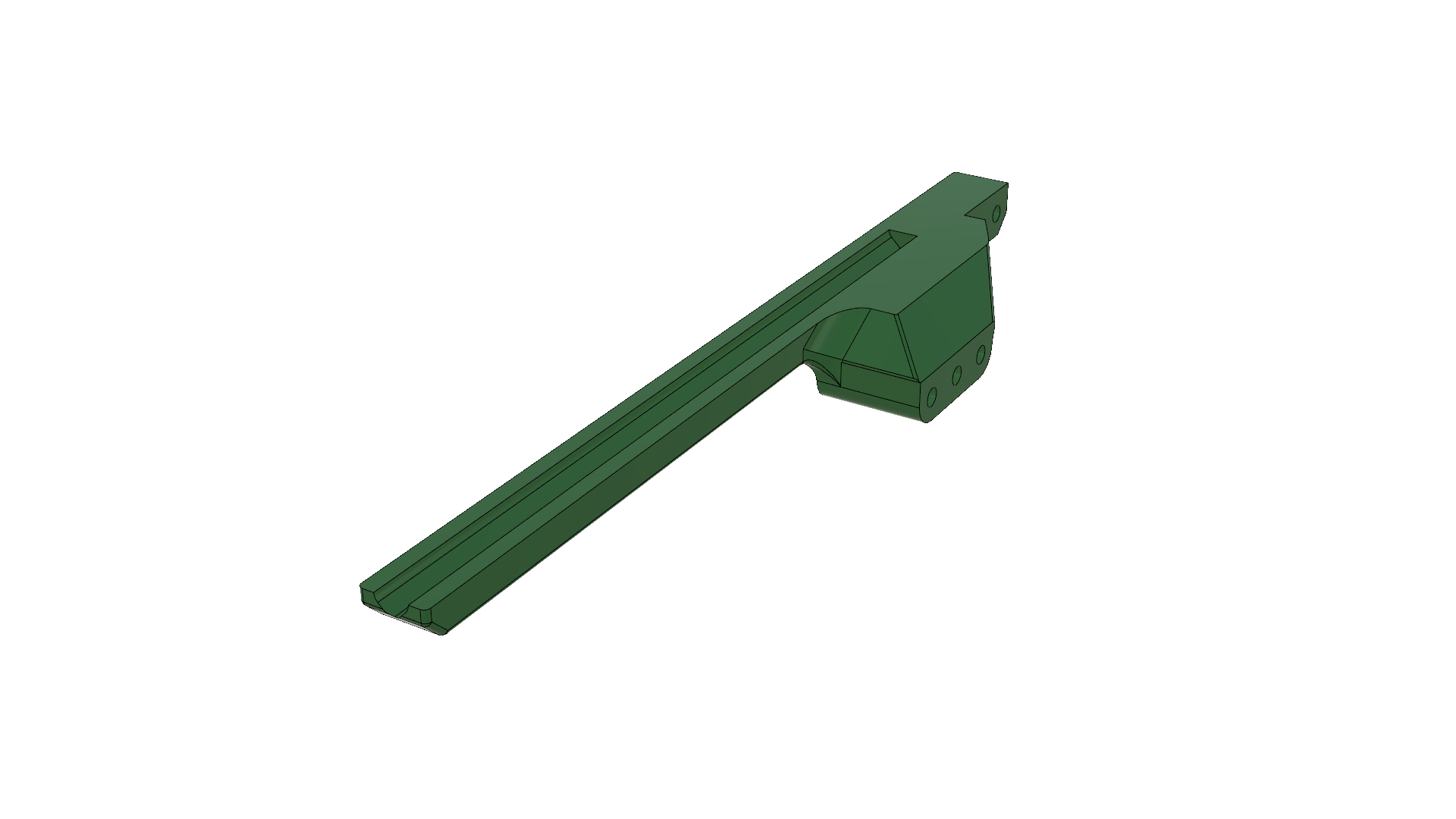
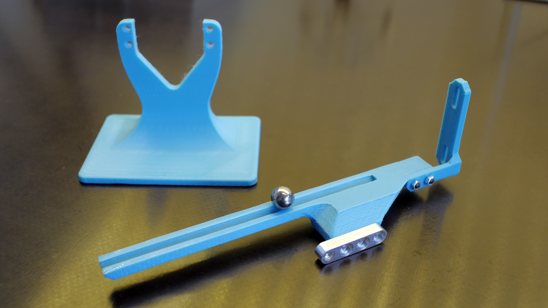
Gutter
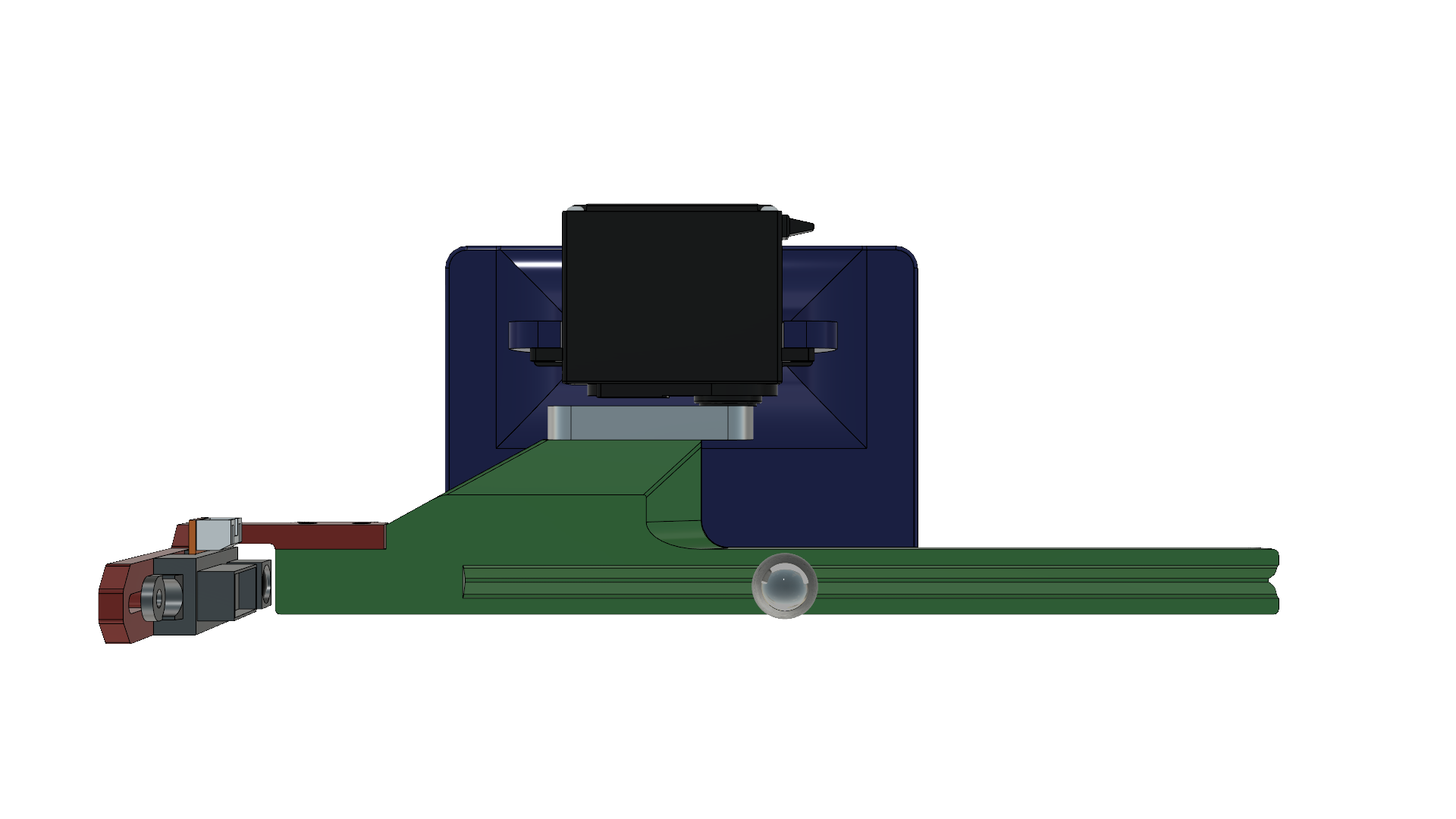
This is the main part of the structure which the ball will be placed on. The ball will only touch the gutter in two places, i.e. the gutter is not formed after the ball. The part is flat on top and everything is moved away from the servo to avoid unwanted readings from the IR sensor. The axis of rotation is in the center of the sum of the length of both the gutter and the sensor bracket. The servo can safely rotate 45 degrees to each side.
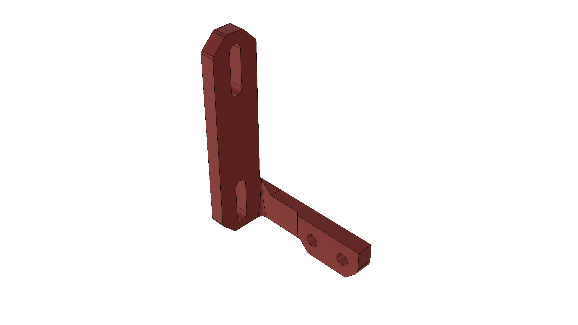
Sensor Bracket
A simple bracket to mount the sensor to. The mounting holes are slots so that we easily can change the height of the servo. The sensor will be mounted far enough away from the gutter such that the ball won’t enter the sub-minimum range of the servo.
Upwards and Onwards
At the time of writing this post we are still waiting for the servo and the sensor. We have however printed the structural parts and used a few M3 bolts to mount some of them together.
Continue reading part 2, where we mount everything together and implement a PID controller on an Arduino.