This project is really something else.
Technoport 2015 hosted a Live Crowdfunding event in Storsalen in Studentersamfundet, Trondheim March 18th 2015. For this event we were tasked to create a pysical installation which would be set up on the stage to visualize in real-time how much funds each contesting team (i.e. company, four of them in total) had raised such that the audience could more easily monitor how each team was doing.
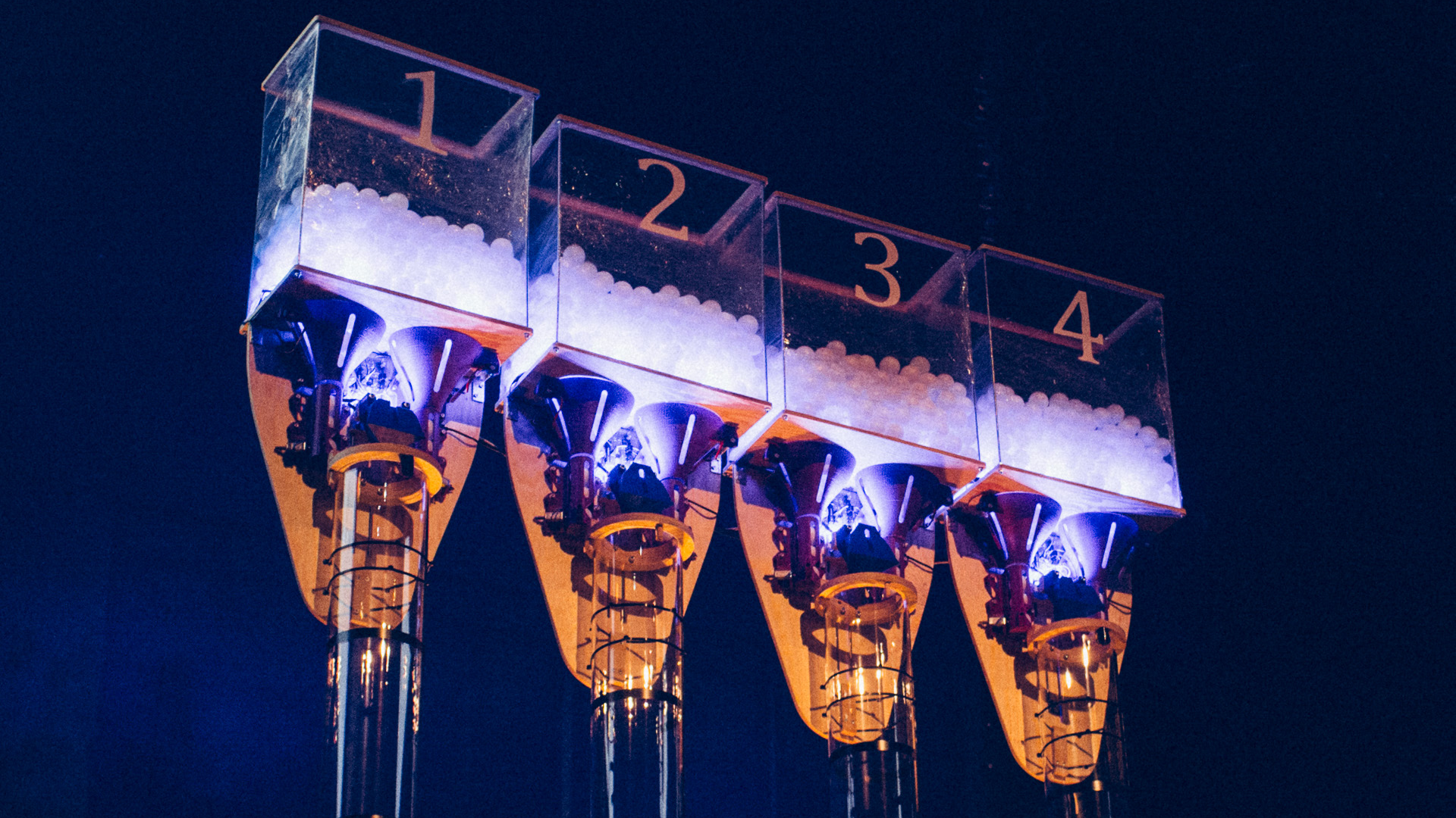
How we wanted to solve this challenge was up to us. We ended up with a scheme where every team has its own 2 m high (15 cm Ø) transparrent plastic pipe, and everytime a team receives funds, ping-ball balls will be shot/dispensed out into that team’s pipe. The more balls in the pipe, the more funds raised.
The Mechanical and Physical Design
This installation ended up being quite complex to design, thus many hours were used within the CAD software. The plan was to have a tank on the very top, one for each team, containing a bunch of ping-pong balls. Underneath those, we would have three sets of 3D-printed funnels to singulate the balls. The three funnels would be arranged in a way such that from above, the funnels would form the corners in an imaginative equilateral triangle, with one in the center in front and one on each side further back.
Under the three funnels we would have the dispensers themselves, also 3D-printed, which would queue up balls to be shot out by a solenoid. The balls would deflect off a prism in the center just above the pipe before falling gracefully down in the pipes. Everything above the pipe would be mounted on a plywood plate which would work as the main structure as well as the structural link between the pipe and the tank.
We ended up scrapping the funnel/dispenser in front and kept only the two further back on each side. This reduced the already demanding 3D-printing task, as well as gave the audience a line of sight into what was really going on above the pipe. On top of that, we maintained a sufficient amount of redundancy for the system.
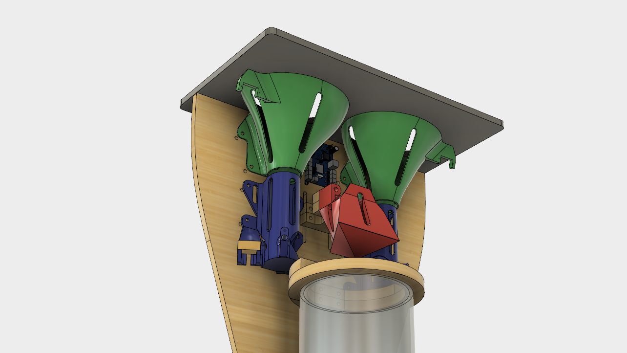
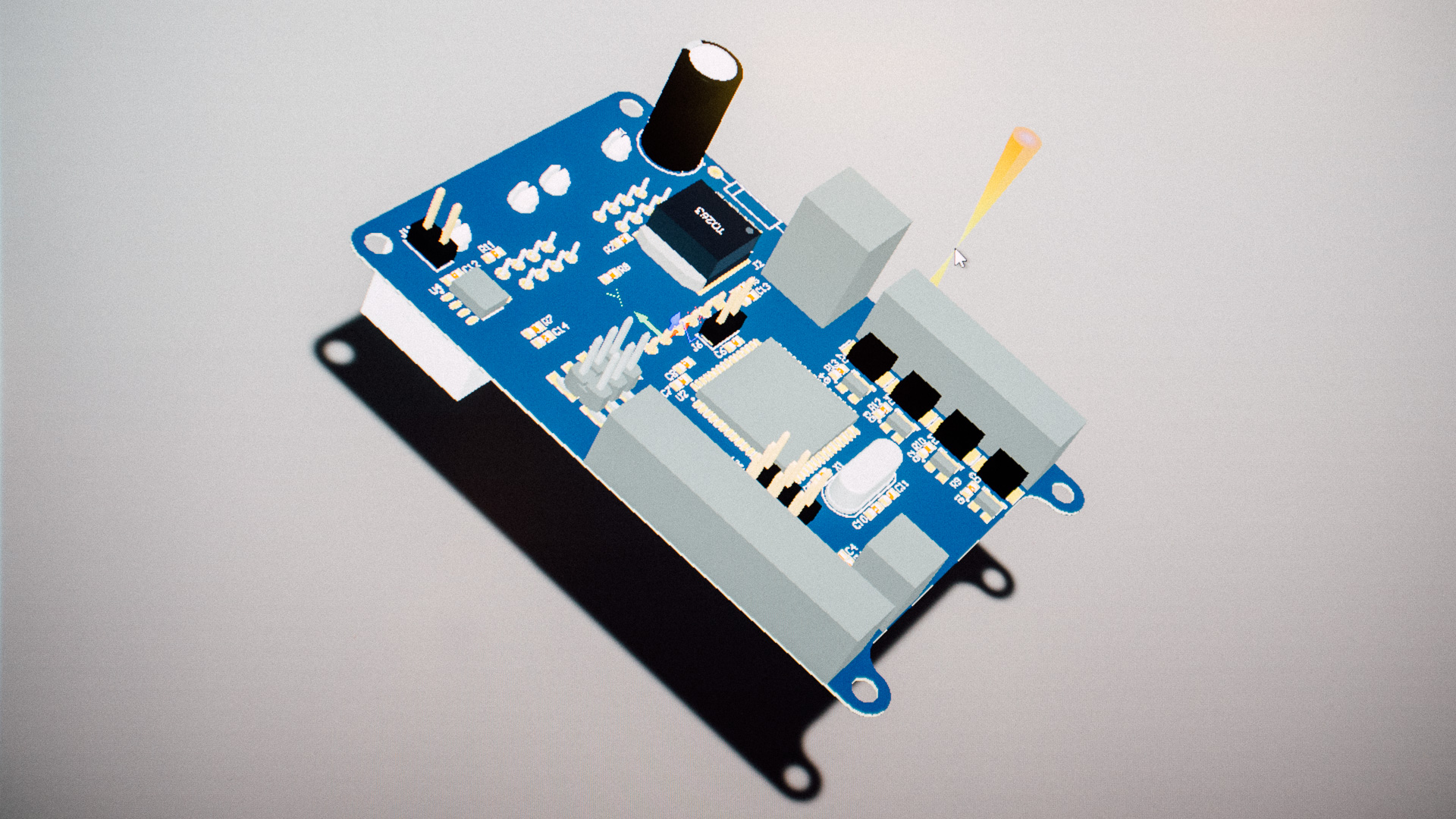
In the image above you can see the final design. The blue, red and green parts were all 3D-printed. The parts with the wooden texture, as well as the grey part (which is the bottom of the tank), were milled out of plywood.
The Dispensers
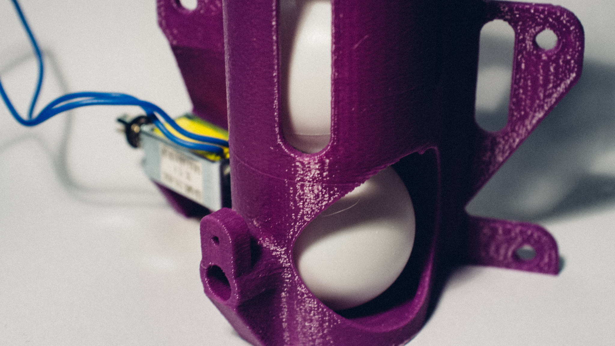
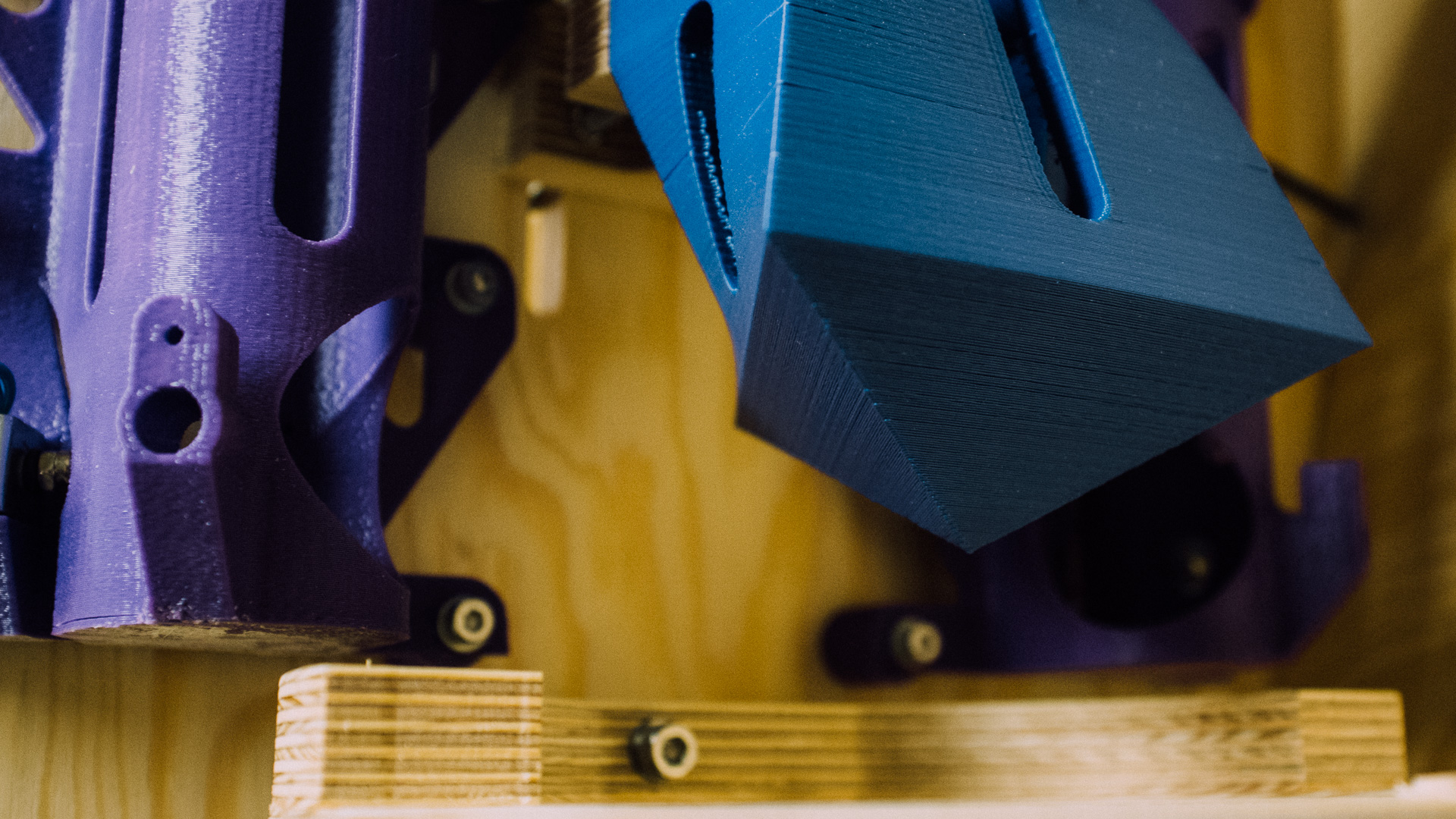
The blue parts are the dispensers with the solenoid attached to them.These were modified several times since the balls had to go smoothly in and out of them (giggity), as well as not fall out when they’re not supposed to. Another challenge we faced was to have a sensor solution where we wanted to sense if a ball was ready to be shot out. We will discuss this later in this post.
The Prism
The red part in the CAD is an overly complex-looking part for its use: it’s only there to deflect the balls coming from the dispensers into the pipe. As you can see, we kept the three-way design on this particular piece. It is only the very bottom part (the upside-down prism) which is used for the deflection. The rest is just there for printing and mounting purposes.
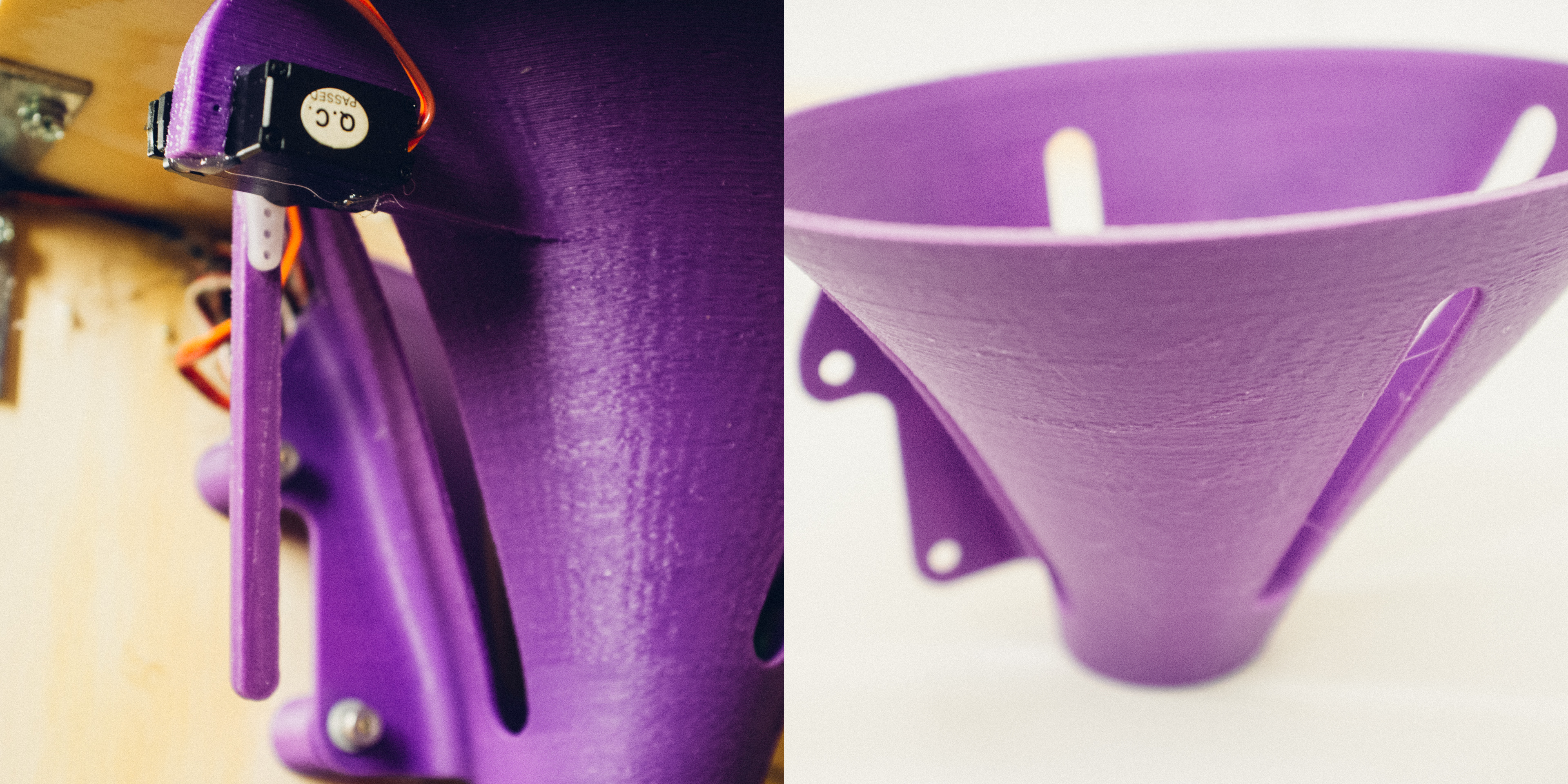
The Funnels
The green parts in the CAD are the funnels leading the balls into the dispenser. The brackets on the outer sides are actually servo mounts. We discovered early that ball jams in the funnels were a regularly occuring problem, so we needed something to unjam everything to keep the flow going. The way we solved this was to have these servos, with an 8 cm long arm attached to each of them, mounted on each funnel. Every time a jam would occur, the servo arm would poke inside the funnel and more often than not unjam it. It’s not the perfect solution, but it worked quite well.
The Tank
The tank on top was the last part we designed. We ended up having a bottom in plywood like the grey part in the CAD picture. In each corner we would fasten the end of a 50 cm long threaded rod. On the top of the rods we would mount a plywood frame and around the rods we wrapped plastic wrap. This may sound a bit shoddy, but it ended up being structurally rigid and not too bad to look at either!
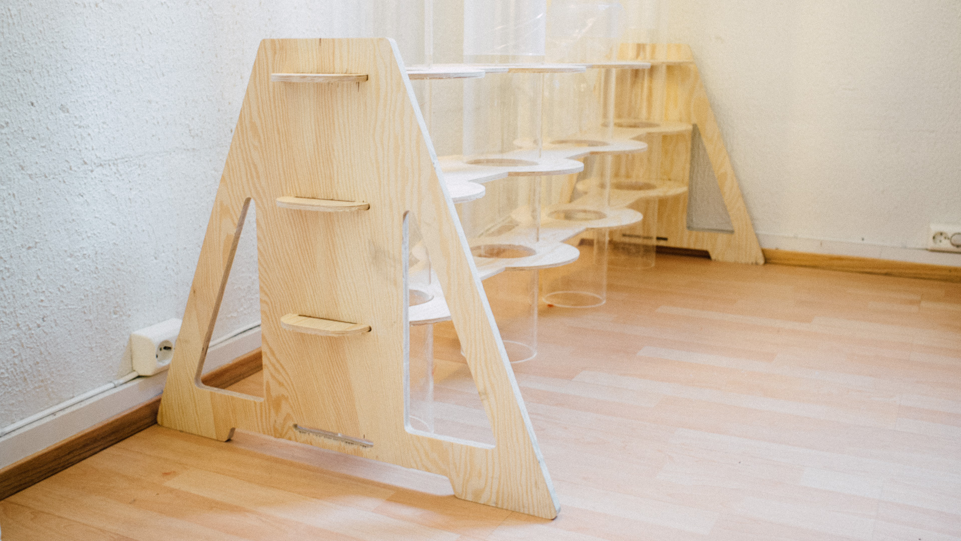
The Rack
Of course we needed something to keep the pipes standing in an orderly fashion. We designed this simple rack which consisted of a set of CNC milled plywood pieces that worked really well.
The Electronics and Software
At first we looked into connecting us to the API of the crowd funding service for a fully automatic system, but with a fully automatic system, the complexity would skyrocket. So we figured out we wanted to keep things simple and fully manual instead since our testing schedule was pretty tight.
PCBs
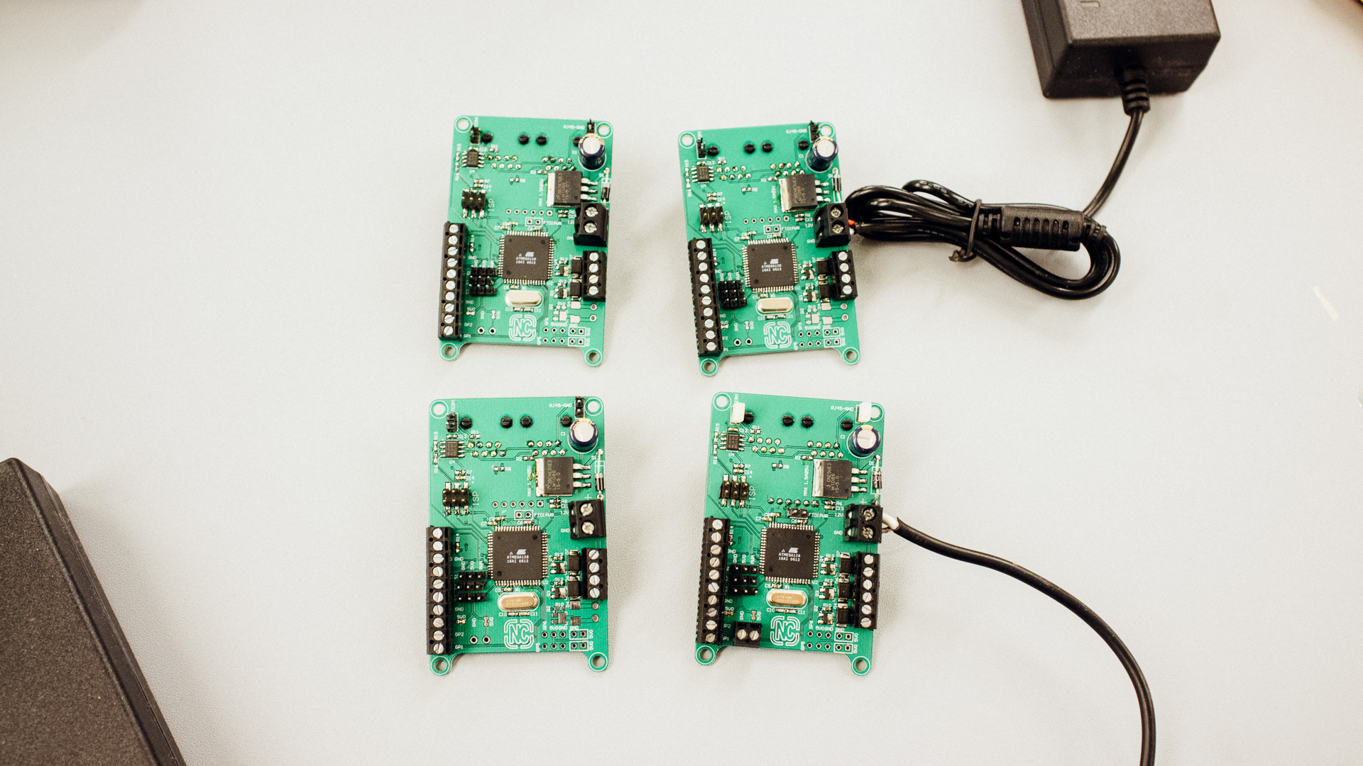
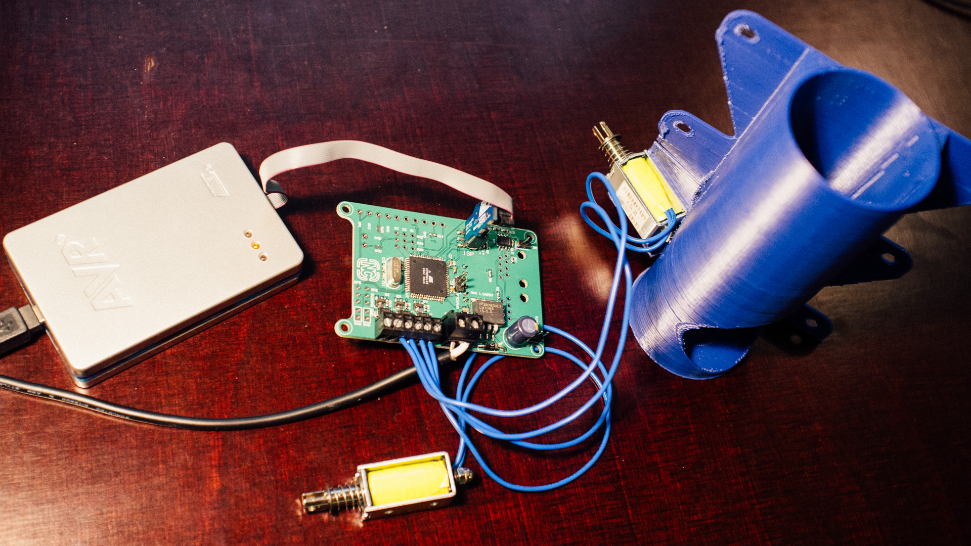
To control the installation we chose a master-slaves architecture, where we have one master-PCB connected to a computer via USB and one slave-PCB for each team. The master talks with the slaves via the sturdy RS-485 definition over a TP cable. That way we should be quite sure all the packages safely arrive at their destination. The master sends commands to the slaves (e.g. fire solenoid 3A or move servo 2B) and the slaves sends status updates back to the master. We designed both PCBs ourselves and sent the designs off to China for manufacturing.
For the logic, we utilized the AVR ATmega128 microcontroller. It’s not necessarily the optimal controller to use for this application, but we had a bunch of them lying around, and they run on 5 V, which matches the servos well. An LM1085 LDO regulator took the voltage down from 12 V to 5 V for the logic and the servos.
Actuation – Solenoids and Servos
We acquired some quite inexpensive solenoids of this type. Since the ping-pong balls are pretty light, they didn’t need to be too powerful, but it was important that the stroke was sufficiently long (around 10 mm) and that it was running at 12 V.
For the servos, we chose to use a few of these miniservos. They did the job and didn’t break down, but they could advantageously have been a bit stronger.
Sensors
As we barely mentioned earlier, we initially wanted to sense when a ball was ready to be dispensed. We ran tests using IR diodes and sensors, and in an ideal world this would’ve worked, but the sensor turned out to be way too susceptible to IR noise to be set up on a stage, even if the collector was quite shielded inside the dispenser. We also tried using laser, but the distance between the emitter and the collector was too short for it to work properly. In the end it didn’t end up being an issue at all since we did things manually from the Control Panel anyway with a clear line of sight into the installation when controlling it.
LEDs
We thought it would be cool with some LEDs lighting up the installation. In the bottom of tank, as well as just on top of the deflection prism we mounted a few individually controllable RGB LEDs (the same type we used in this project). The single LED in front was on all the time, while the ones in the bottom of the tank worked as an alarm to get the audience’s attention. Before we started shooting out balls, we turned on the LEDs in the tank which would run this “inverted sawtooth wave” program for the short duration of that particular ball-dispensing session.
Control Panel
We made a control panel in Python using TkInter from where we could control each and every solenoid and servo from as well as the LEDs in each tank.
Continue reading about the building phase in part 2!