ROBOT BUILDING
Tuesday, June 9, 2015


This machine is based on the open source PlotClock by joo over at Thingiverse. Original content available here: http://www.thingiverse.com/thing:248009/
You can find firmware and .STL-files for 3D-printing here: https://github.com/NorwegianCreations/embedded.TRD
Workshop tasks:
- Install and test the Blend Micro (Arduino): Scroll down for instructions. You can test with the “Blink” under “File->Examples->01.Basics->Blink”. Remember to select the correct board under Tools (Blend Micro 3.3V/8MHz)
- Build the mechanical part of the robot. Assembly Instructions #1-9
- Wire the cables. Assembly Instructions #10
- Load the firmware. Assembly Instructions #11
- Calibrate the Robot (in firmware). Assembly Instructions #11
- Make it draw a custom symbol. Assembly Instructions #12-13
The Original Design
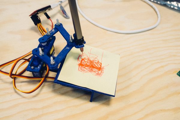
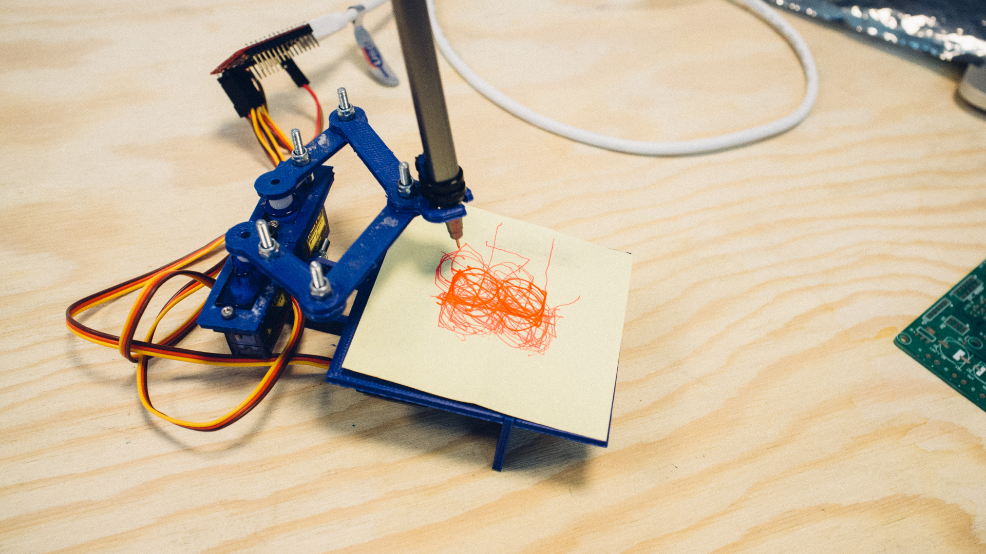
The PlotClock is a servo actuated drawing machine designed to draw the time each minute. It uses a non-permanent marker on an acrylic surface. Right before it draws, it uses a sweeper to wipe away what’s written there from before.
Our Modified Design for Embedded.trd
Instead of writing the time, we have made a simple modification to the code where you send a single digit (0 to 9) over serial to the Arduino which the machine then draws on a post-it note. We have changed the size of the drawing plate and customized the pen holder to fit the markers we’ll be using. We have also 3D-printed the parts instead of laser-cutted them out from acrylic sheets.
We encourage you to experiment with the code and make some really cool stuff yourselves. The framework from the original code is still there for you to use.
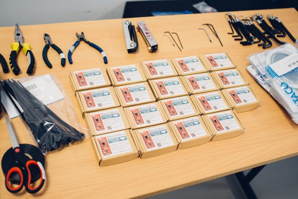
Assembly Instructions
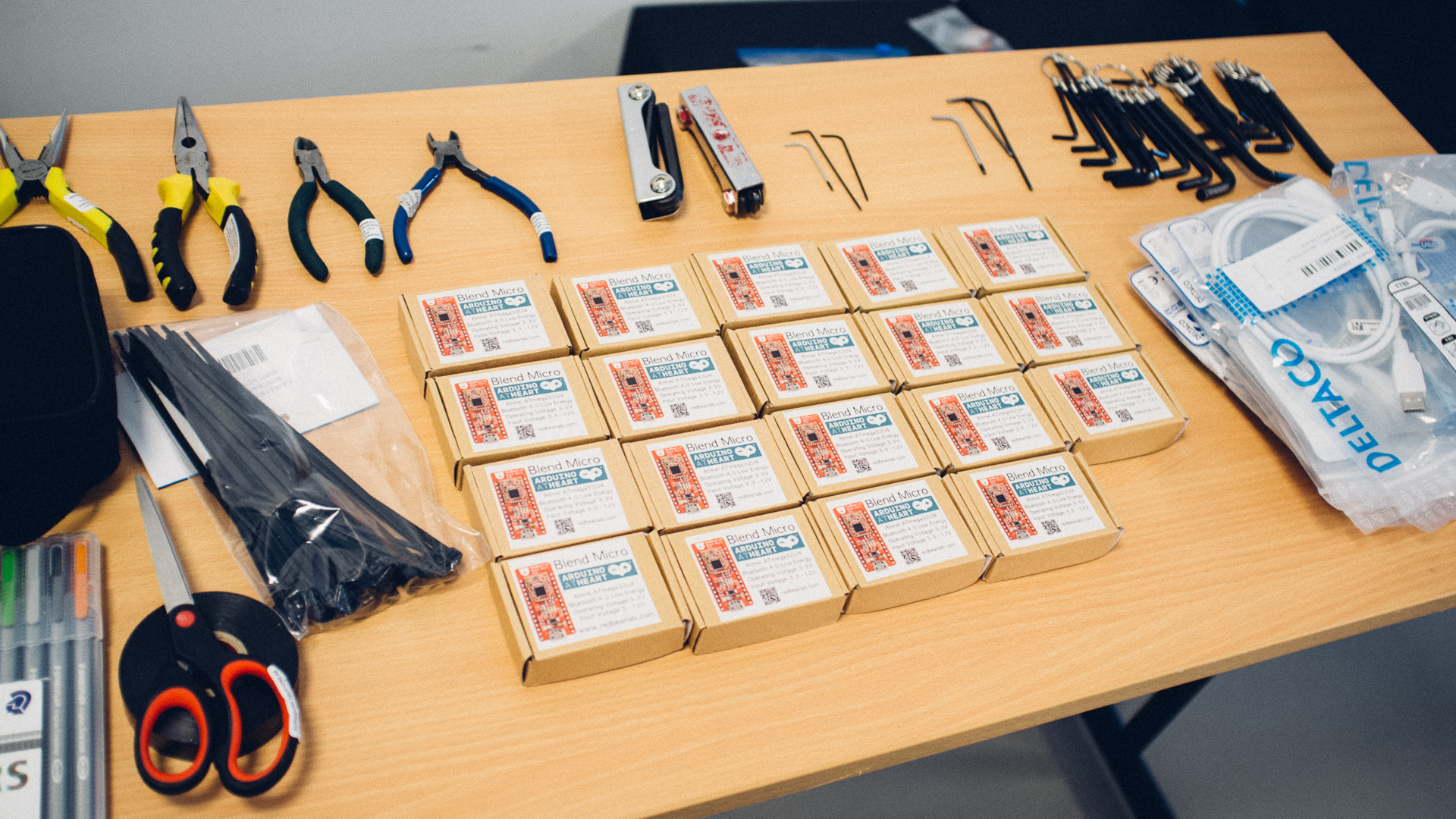
Kit Contents
- 1 Wire connector (splitter)
- 3 servo sets
- 1 set of 3D printed pieces
- 10 M3 bolts (at least two black 12mm bolts)
- 6 M2 bolts
- 8 M3 locknuts
- 2 M3 nuts
- 2 zip ties
- 1 Utility knife
- 1 3D printed M3 wrench (if too small, mod it with your knife)
- 1 Pen (randomly colored, feel free to swap with the guy next to you, or ask us for a different color)
- Post-its
Tools and Items Needed
Those not included in the kit are available from a shared tool pool and should be returned after the workshop is over.
- Blend Micro board (Arduino)
- Utility knife (included)
- 2.5 mm hex key for the M3 bolts
- 1.5 mm hex key for the M2 bolts
- 3D printed wrench (included) for the M3 locknuts
- Wire cutter for the zip ties
Other Tools and Items Available
- Electrical tape
- Scissors
- Needle-nose pliers
- M2 nuts
- Glue gun
Step-by-step
Click on the images for larger versions.
1. Prepare the 3D printed pieces
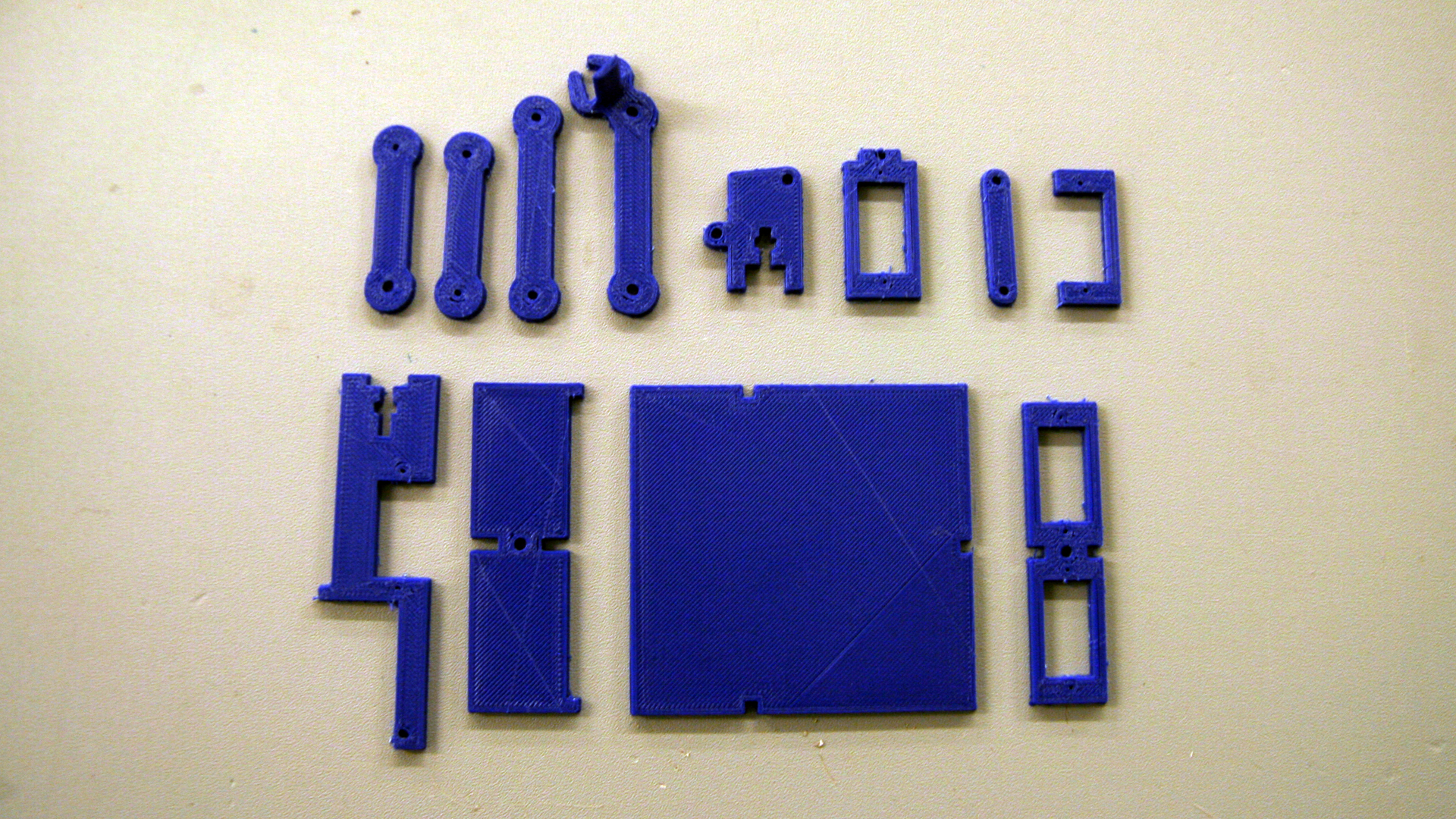
In step 2, 4 and 9 you will find that the gaps in the 3D-printed pieces are too small. Therefore, you will need to use the utility knife to cut away some of the material in order to make everything fit nice and tight. Be careful not to cut away too much.
The servo slots should be kept as they are, though. They should fit quite well.
Do this step as you go through the rest so that you know what piece goes where.
2. Fasten the vertical pieces together
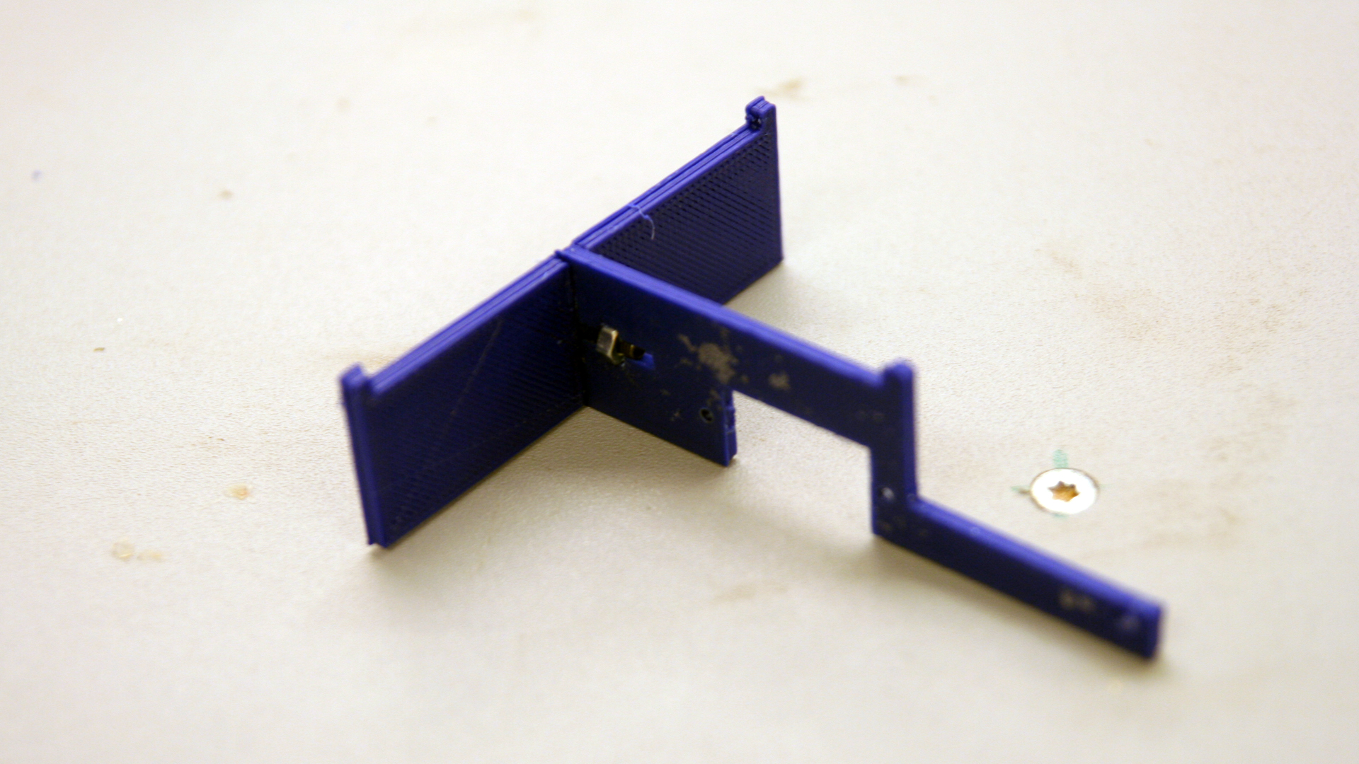
Use one black 12mm M3 bolt and one of the regular, non-locking nuts to fasten these to pieces together. The other bolts are too long. The nut goes into the appropriate slot (as shown in the image above).
3. Fasten the “tilt piece”
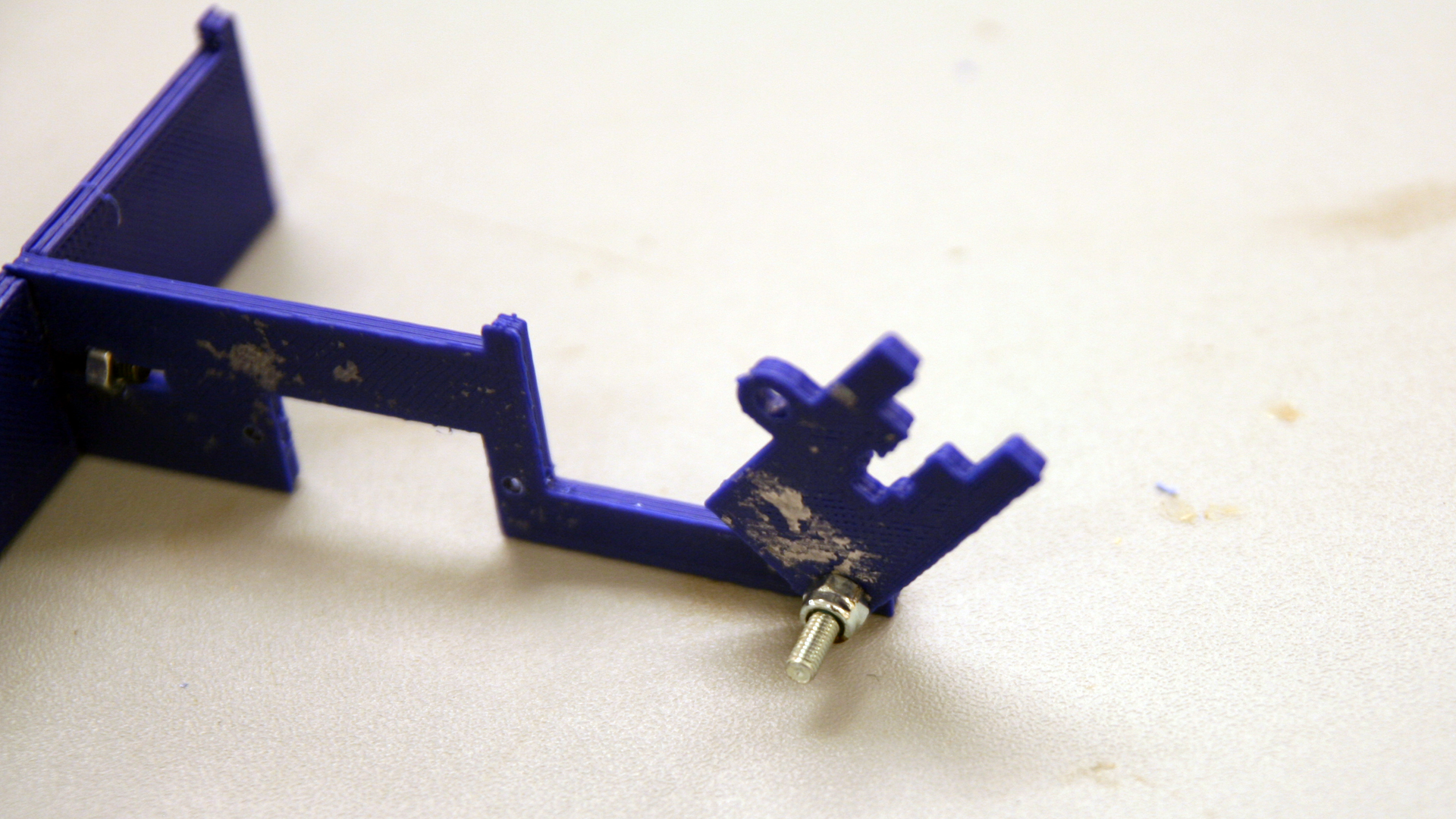
If you only have two black 12mm M3 bolts, save the last one for step 4 and use one of the longer ones instead. Fasten the piece as shown in the image above and use a locknut to tighten it “just about right”. It should be firmly tightened, but still able to rotate without much resistance.
4. Fasten the single (closed) servo bracket and double servo bracket to the tilt piece
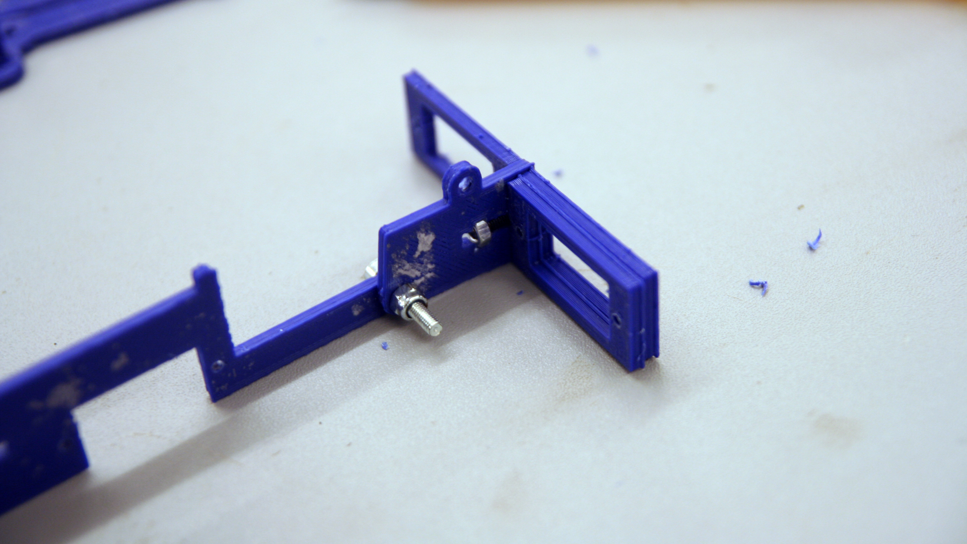
Use a black 12mm M3 bolt and the remaining regular, non-locking nut to fasten the brackets as shown in the image above.
5. Fasten the single (open) servo bracket and one of the servos to the “spine”
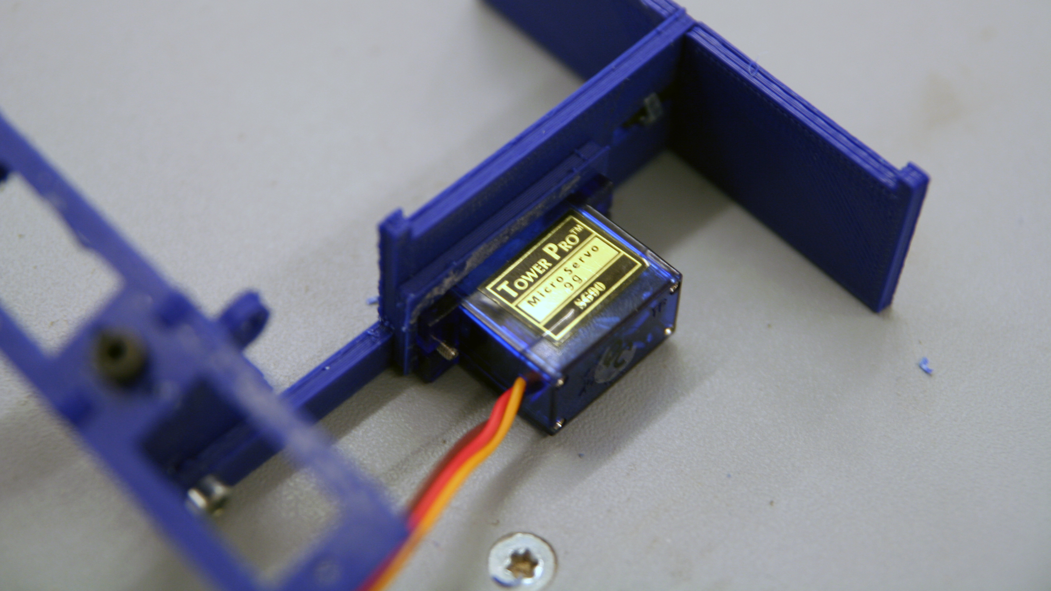
With two M2 bolts, fasten the bracket and the servo as shown in the image above. You don’t necessarily need nuts to fasten the servos since the bolts will thread themselves sufficiently into the servo holes. If you need M2 nuts, ask us and you shall receive.
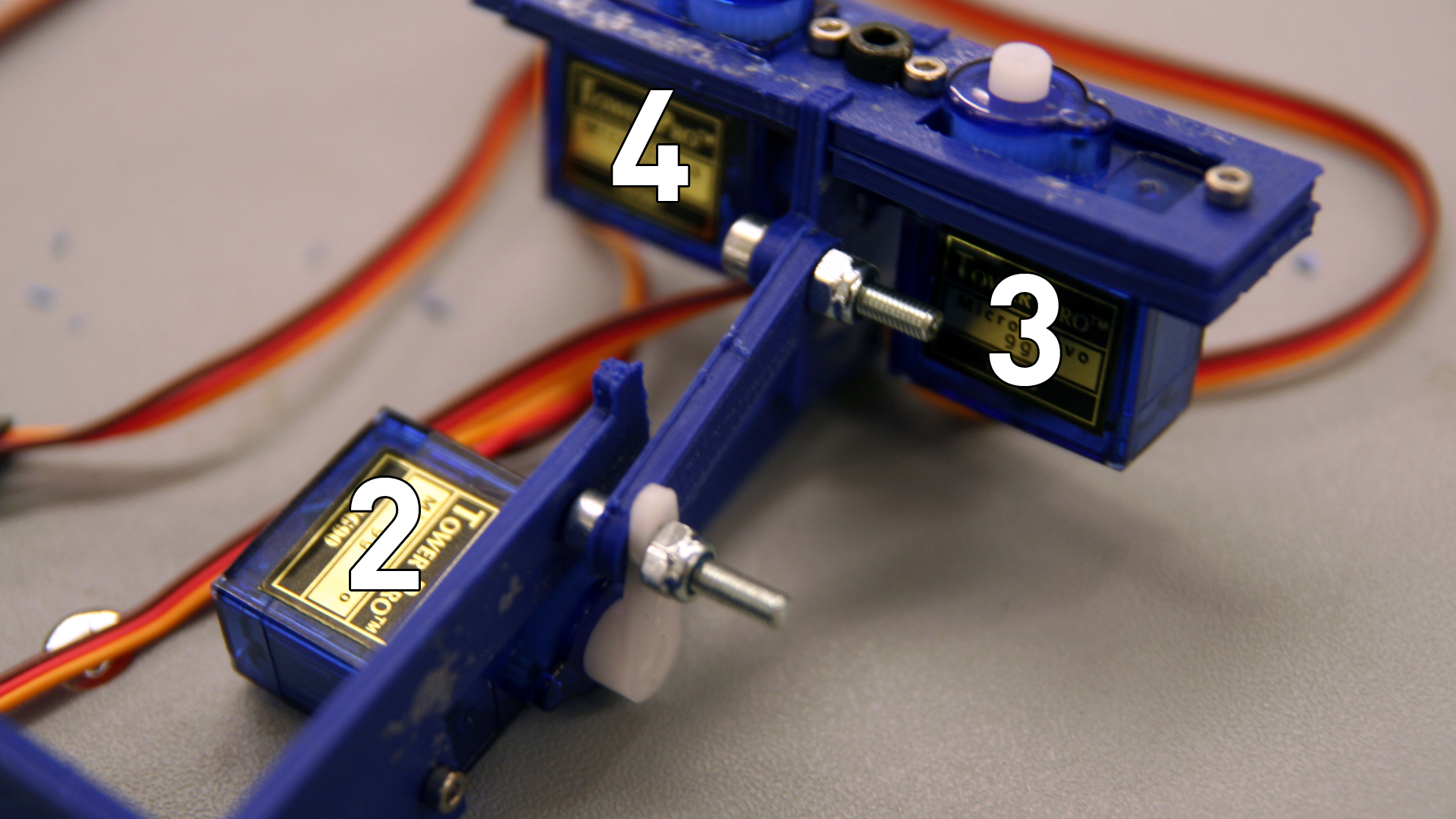
6. Fasten the remaining servos
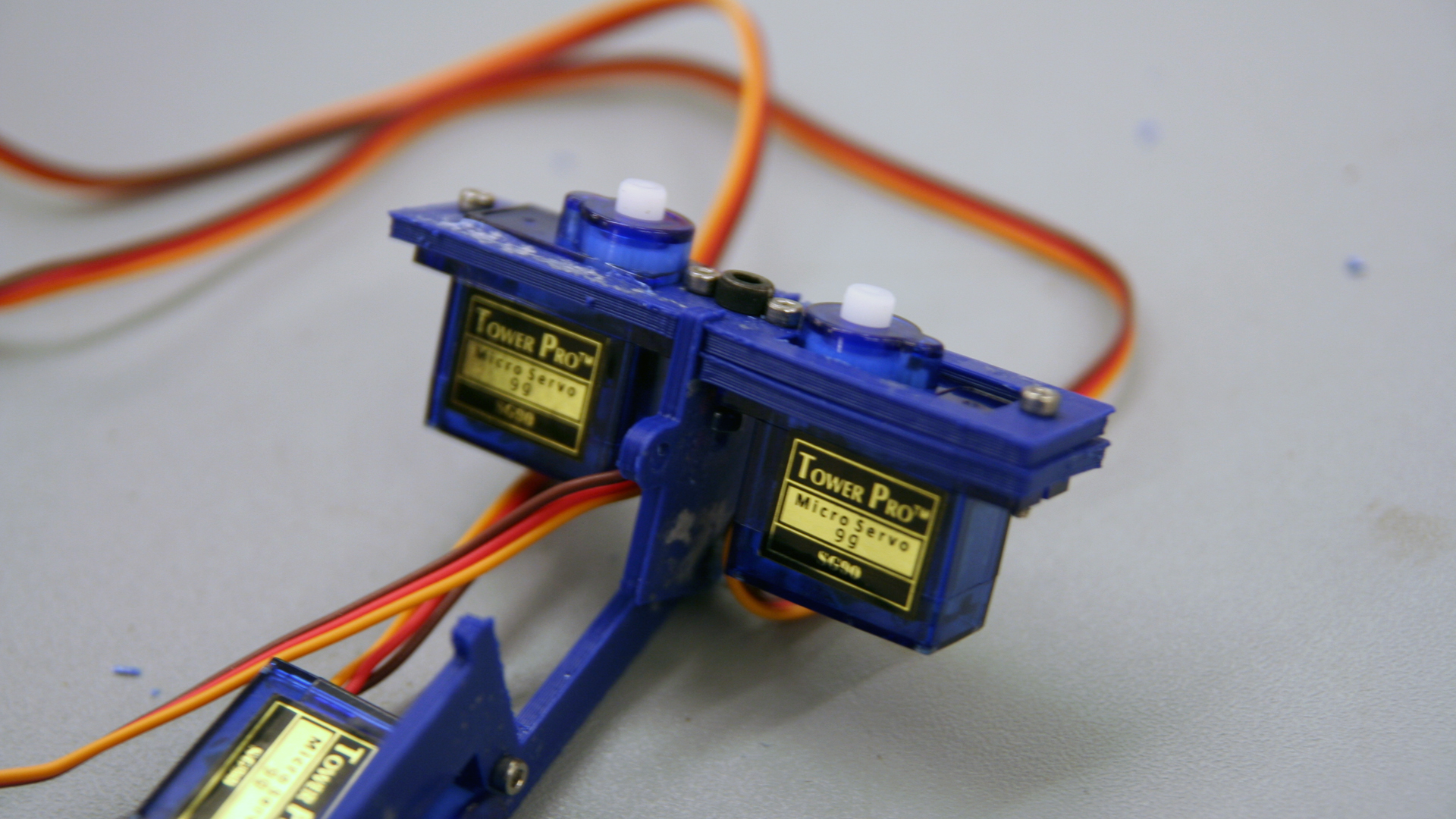
Attach the remaining two servos to the double servo bracket as shown using the remaining M2 bolts. You might need to apply some force to get the servos in place.
7. Attach the lift-arm
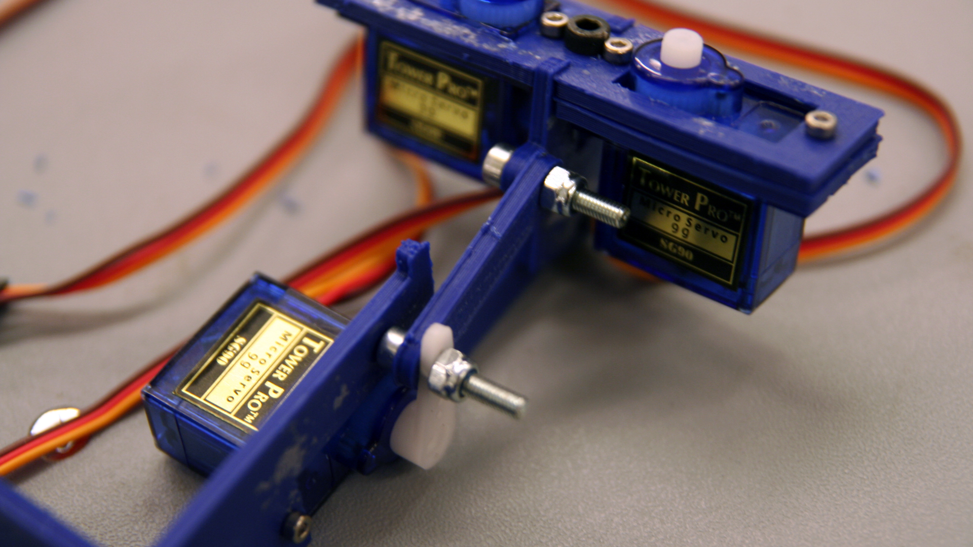
Be sure that the lift-servo shaft is in an approximate center position. Fasten everything (including the white servo arm) properly with two M3 bolts and two locknuts such that everything rotates smoothly before fastening everything to the servo spline itself. That way it’s easy to feel that the nuts are tightened just right. Doublecheck that the movement within the servo range is sensible. If not, reattach the servo arm in a different angle on the servo spline. You don’t need to fasten the servo arm to servo with a bolt.
8. Create the XY-arm
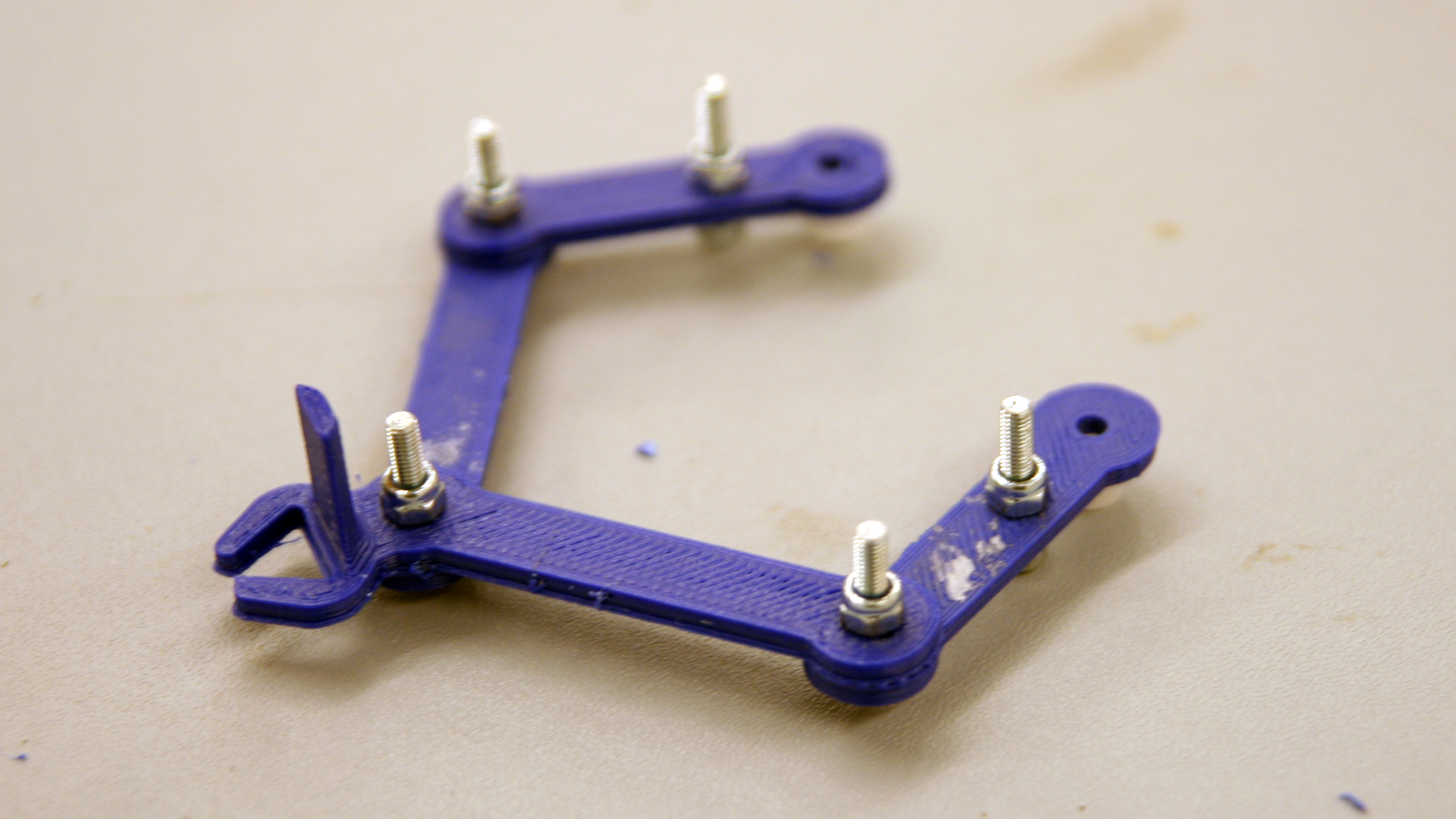
Use the remaining five M3 bolts and locknuts to create what you see in the image above. The joints should be tight while at the same time rotate without much resistance. The white servo-arms should be fastened much tighter such that the don’t rotate out of place (not so tight that you start bending the servo arm).
9. Fasten the XY-arm to the servos and the drawing plate to the vertical pieces
Maker sure the XY-servos are in a center position when mounting the XY-arm in a sensible position. If the drawing plate is too loose, add some tape or glue. As with the lift-arm, you don’t need bolts to attach the servo arms to the servos.
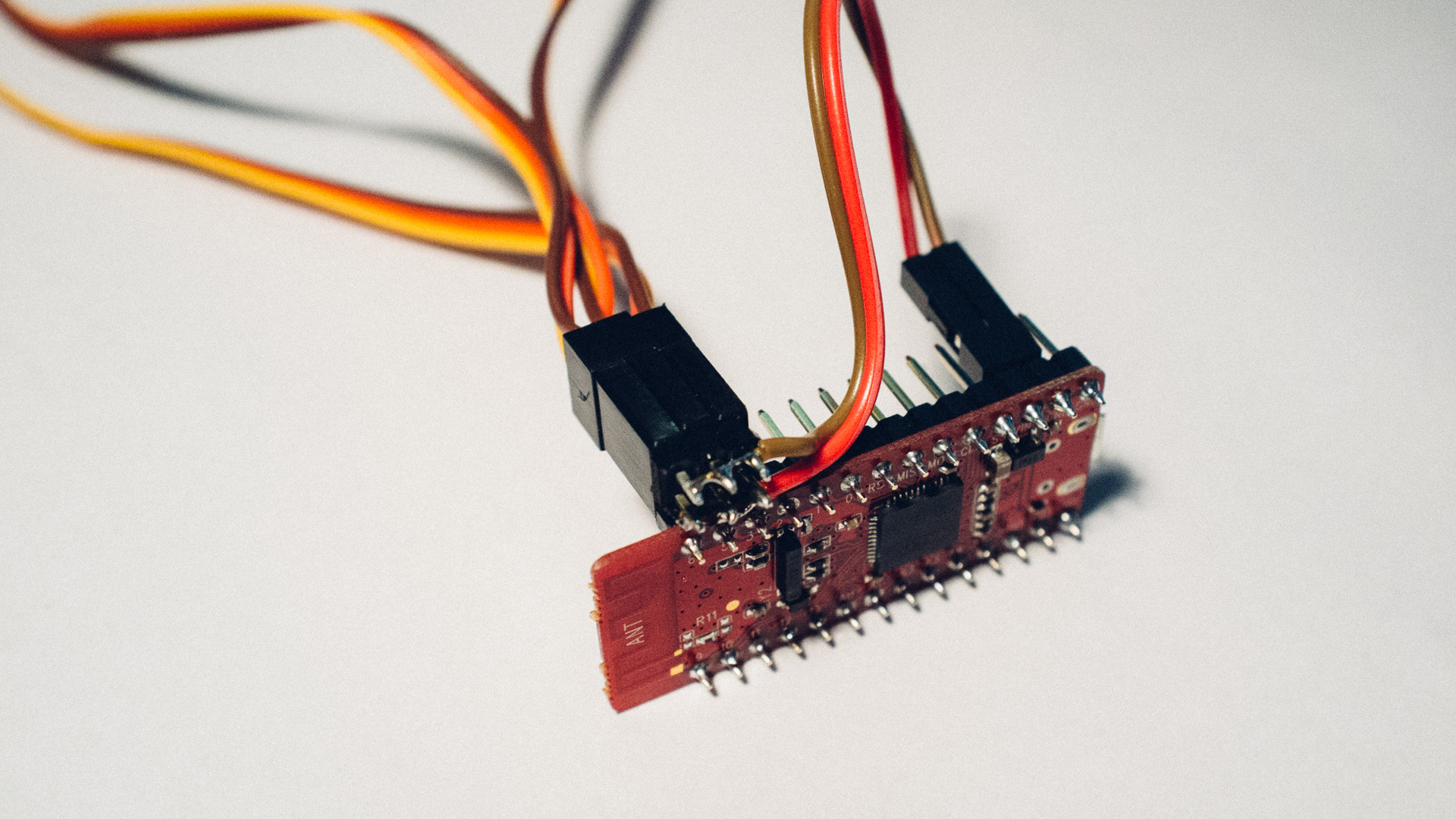
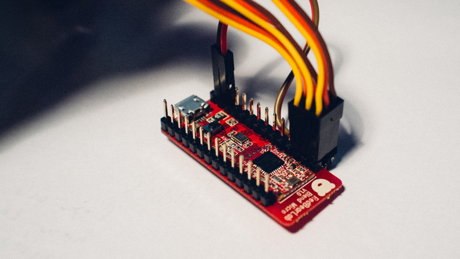
10. Hook up the Arduino compatible Blend Micro
You have one wire connector (splitter) that looks like this:
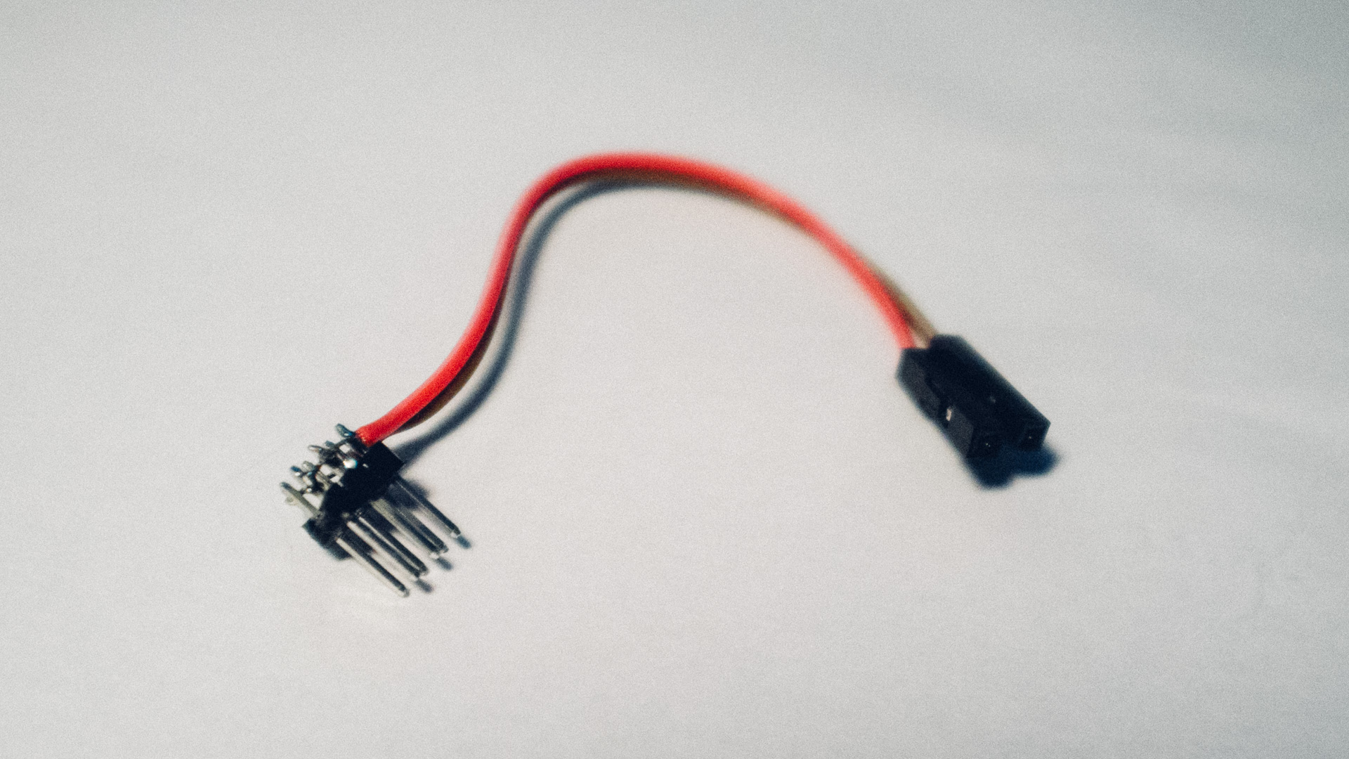
That piece is going to give the 3 servo motors power and ground.
The board is 3.3 V, and the servo motors are 5 V. They can understand a 3.3 V PWM control signal, but need 5 V supply. To give them this we need to use the VIN pin on the Blend Micro. This is directly connected to the USB voltage which is 5 V. Note that the board does not contain any protection, making it easily possible to draw too much current from your computer’s USB port, and activating the current protection there.
Connect the splitter to all the servo cables like this:
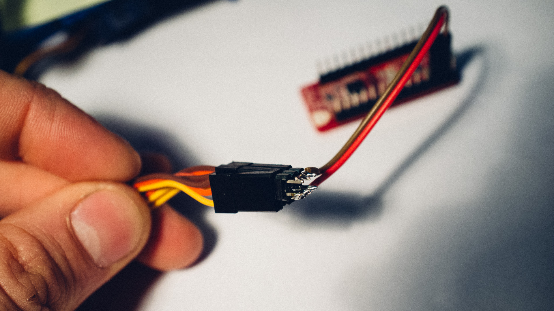
The orange pin is the signal. They need to be connected to the Blend Micro board on pin 3, 5 and 8 (on the end of one of the sides). Connect the right servo (looking from behind) to number 8, the left to number 5, and the lifting servo to number 3. (You can change pinout in the firmware).
11. Program the Arduino and calibrate the servos
Program the Arduino with the “plotclock_nc.ino” code availiable in the Firmware folder in this repository: https://github.com/NorwegianCreations/embedded.TRD.
Make sure that you haven’t attached the pen yet.
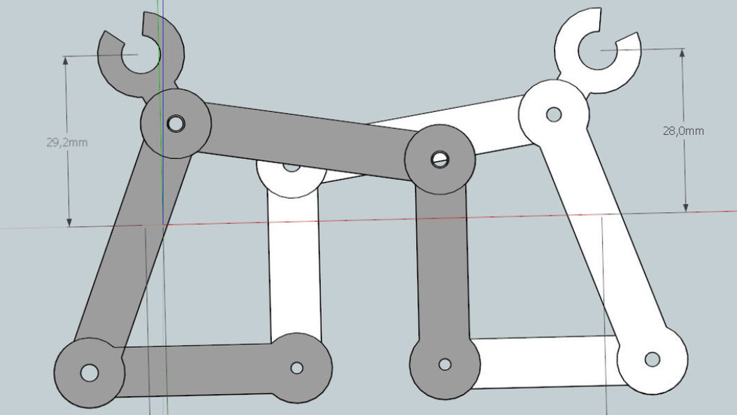
By default, the code is in calibration mode. This means that it loops a pattern which is used to eyeball that the XY servos are calibrated correctly. The two end-positions in the calibration cycle should optimally look like the image above (notice the 90 degree range).
To adjust the XY-calibration, change the values of the SERVOLEFTNULL, SERVORIGHTNULL and SERVOFAKTOR values. The …NULL values defines the angle offset while the SERVOFAKTOR value defines the range.
You can also adjust the LIFT0 and LIFT1 values to calibrate the lift.
To exit the calibration mode, comment out the #define CALIBRATION line.
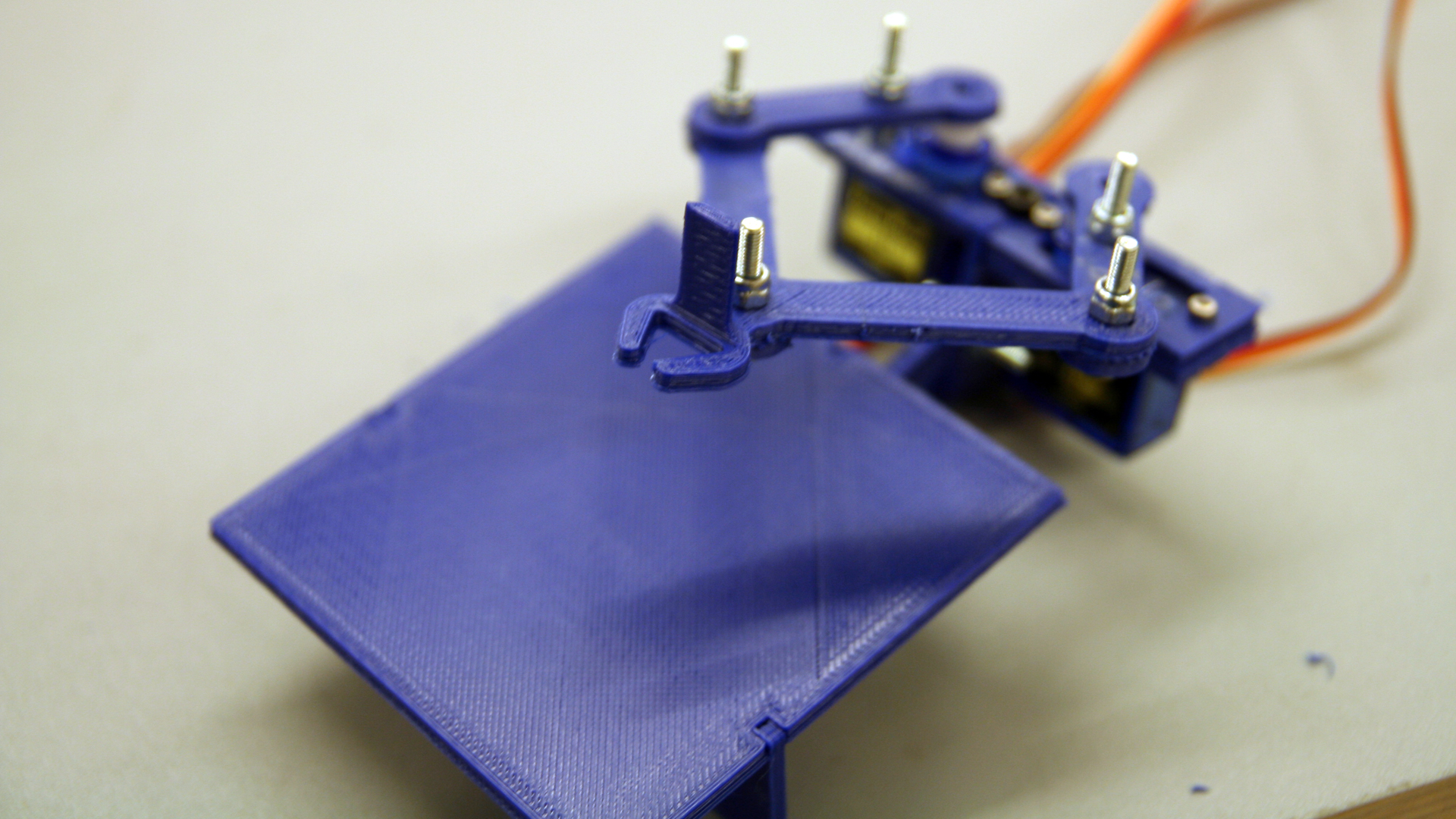
12. Attach the pen to the XY-arm
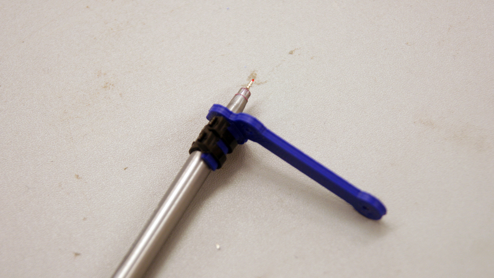
Push the pen firmly down into the slot and fasten it properly with zip ties as shown in the image above. (Don’t be alarmed by the severed arm in the image. Yours will hopefully still be well attached to the rest of the machine at this point.)
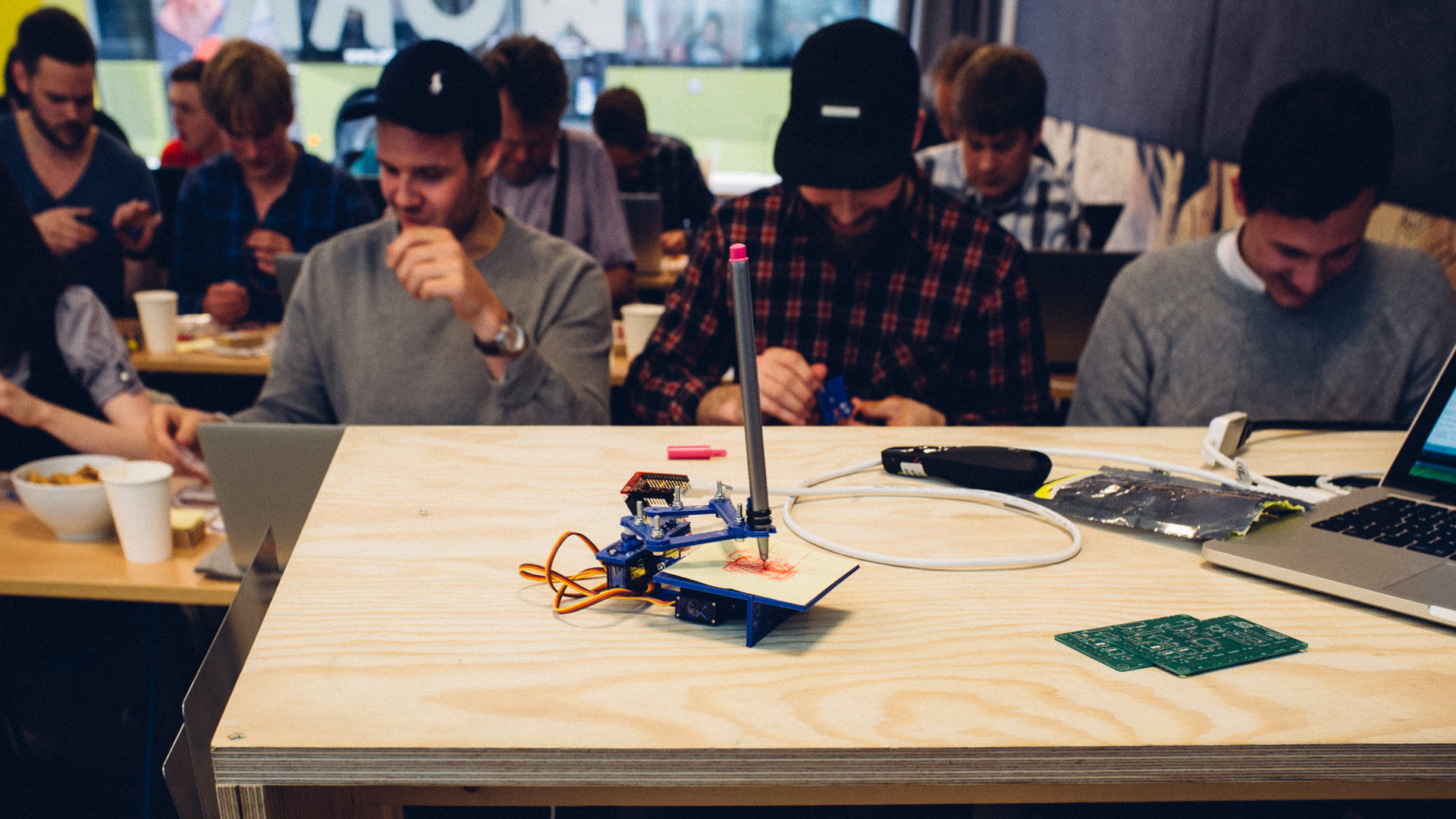
13. Test and experiment!
Try sending single digits over serial (default baudrate: 115200) and see if the machine works.
Experiment with the code make some cool stuff on your own!
Tips for further experimentation:
- Make it possible to send and draw letters in addition to digits
- Make it possible to draw more than one digit/letter at a time
- Draw other patterns (logos, smileys etc…).
Blend Micro
Embedded.TRD use among other things Blend Micro.
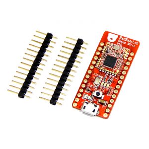
This board requires some set up to make it Arduino compatible.
You can follow the instructions HERE, to install it in the newest Arduino IDE.
(The board link: https://redbearlab.github.io/arduino/package_redbearlab_index.json)
OR
Follow the getting-started-instructions HERE, and make sure you download Arduino IDE 1.0.5, from the previous releases HERE.
More information about this board is available here.
Drivers
No need to do this if you are using POSIX systems like Linux or Mac OSX, but Windows drivers can be found HERE.