Last year we made a Christmas card heavily influenced by our fields of expertise and what we deliver.
This year was no exception!

What’s new this year, among other things, is the different design, and that there exists several variants of the cards.
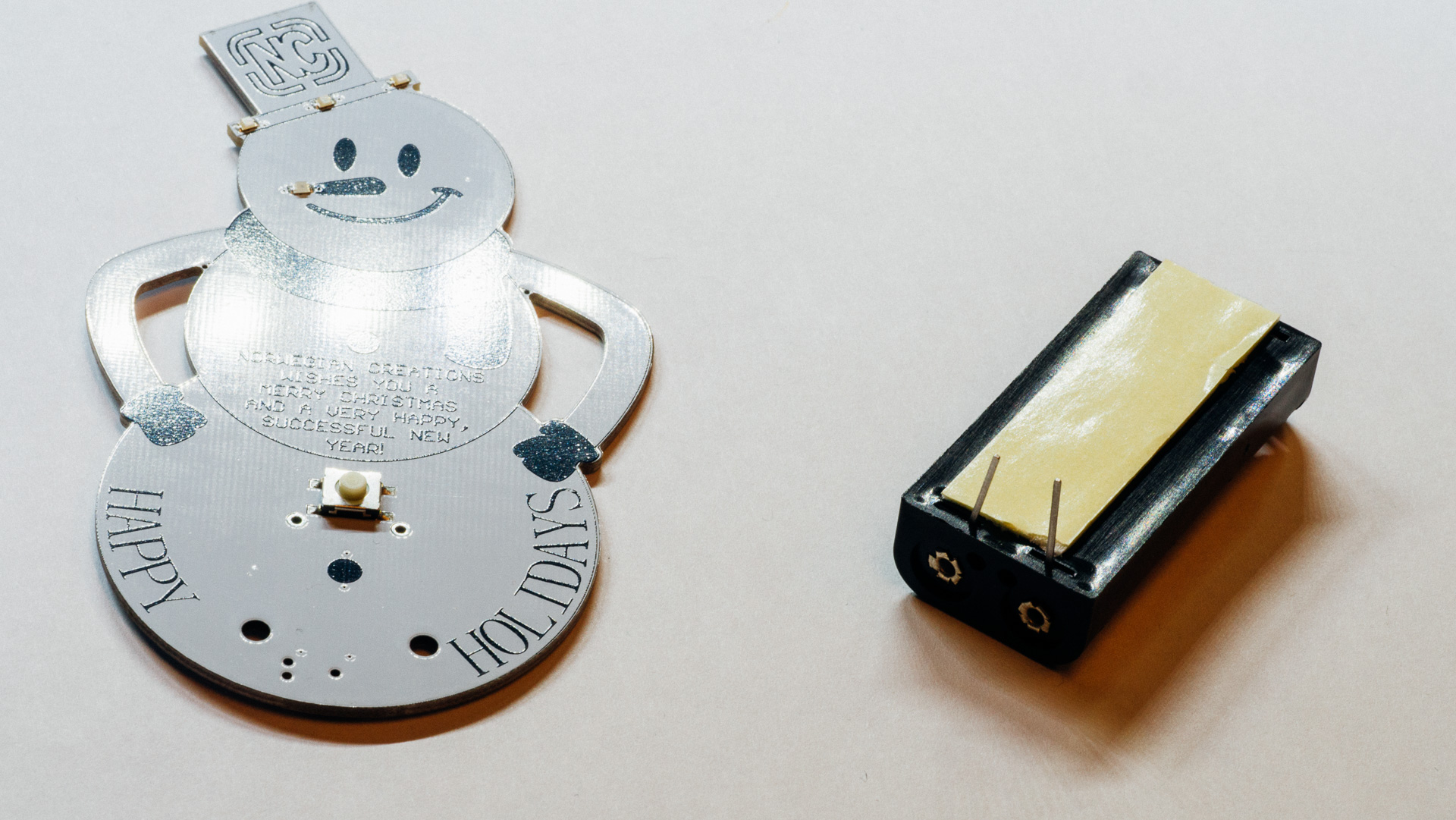
It’s still a rather simple system with just a couple of LEDs, an ATiny10 microcontroller, a battery holder and the necessary “support”.
The Original variant: This is the Variant we are distributing ourselves. It’s completely assembled, programmed and tested in-house before delivery. We also includes “stands” and batteries.
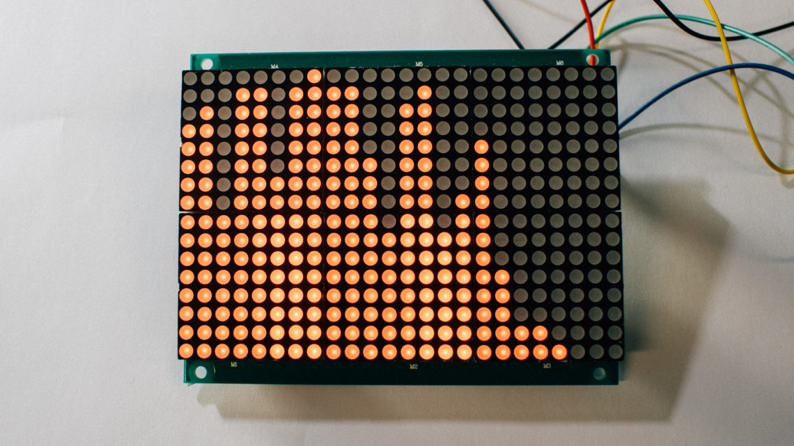
This variant is the one in all the pictures in this post.
The PCBWay variant: ~10 k units was produced without our logo and have been delivered to customers of PCBWay.
This post will serve as an “AS-IS” instruction for those that want to make their “PCBWay variant” operational.
If you received this variant, feel free to mention it in the comments!
Electronics
Schematic
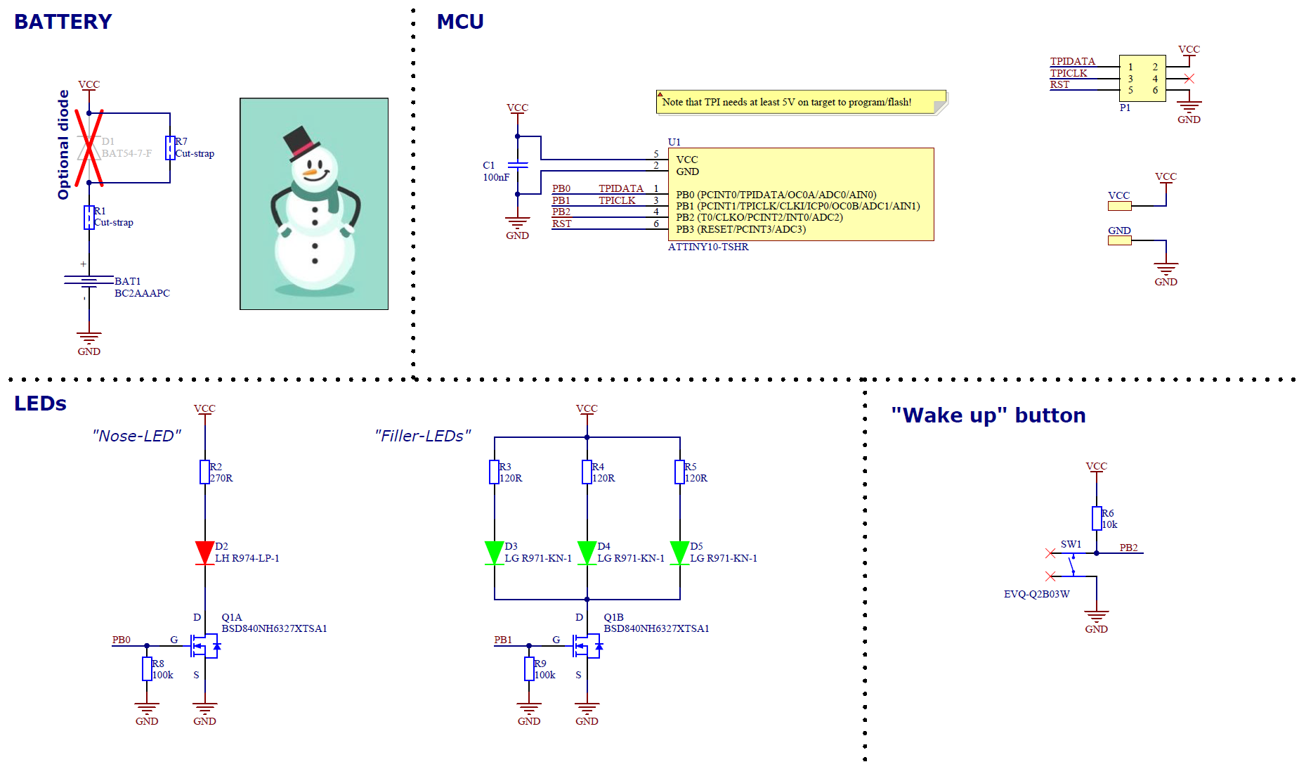
The diode D1 (with a cross over) can protect the system from wrongly inserted batteries.
Here it’s bypassed through R7, but it’s possible to cut R7 and mount the diode.
All the cards we distributed already have the batteries correctly inserted, so no need to worry about releasing the Magic smoke there:)
The system should be able to withstand wrongly mounted batteries without D1 present.
Components
On the front side of the card we have removed things like designators and direction markings to make the cosmetics all right.
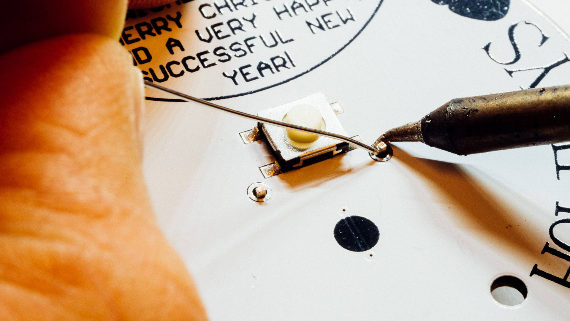
The designators and directions for the LEDs are shown in the image below and the only other part on the front side is the button that has the designator SW1.

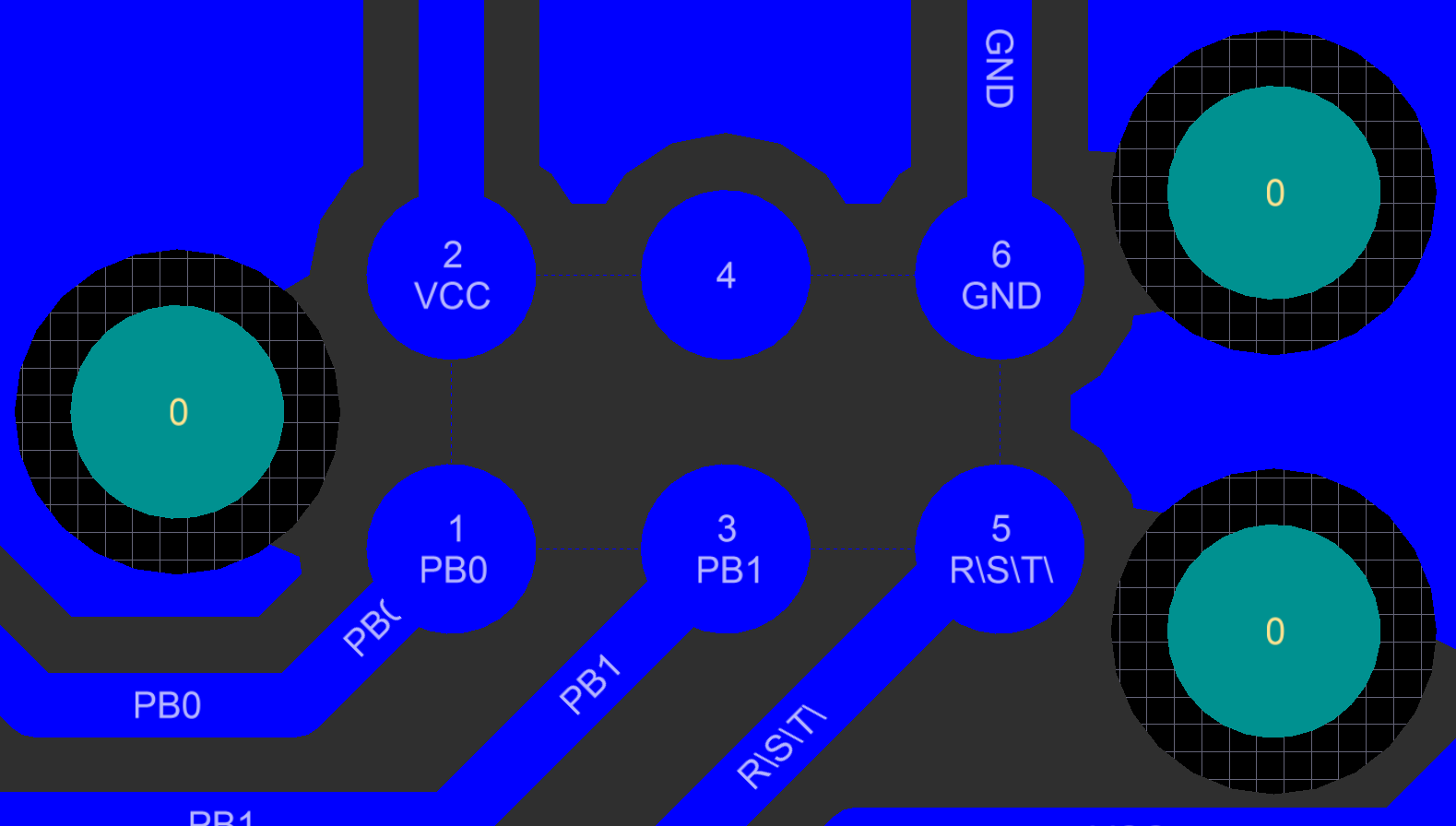
The programming header is compatible with a 6 pin TC2030-CTX-NL tag connect and the pinout on the PCB is the same as in the schematic. But anyways, this is from the backside on the PCB:
A simple BOM for the components on this card:
Designator, Description, Manufacturer, Manufacturer Part Number, Quantity, Value, Comment
U1, IC MCU 8BIT 1KB FLASH SOT23 ATTINY10-TSHR,Microchip Technology, ATTINY10-TSHR, 1, ,
BAT1, HOLDER 2 AAA CELL W/PC PINS, MPD, BC2AAAPC, 1, , This must be mounted to the PCB with double sided tape or something like that
Q1, MOSFET 2N-CH 20V 0.88A SOT363, Infineon Technologies, BSD840NH6327XTSA1, 1, , BSD840NH6327XTSA1
C1, CAP, , ,1, 100nF, 0603 CAP min. 5V
SW1, SWITCH TACTILE SPST-NO 0.02A 15V, Panasonic Electronic Components, EVQ-Q2B03W, 1, ,
D3 D4 D5, LED GREEN DIFFUSED 0805 SMD, OSRAM Opto Semiconductors Inc., LG R971-KN-1, 3, , Direction crucial. See picture
D2, LED RED DIFFUSED 0805 SMD, OSRAM Opto Semiconductors Inc., LH R974-LP-1, 1, , Direction crucial. See picture
R2, RES, , ,1, 270R, RES 0603
R3 R4 R5, RES, , , 3, 120R, RES 0603
R6, RES, , , 1, 10k, RES 0603
R8 R9, RES, , , 2, 100k,RES 0603
You should be able to source all the necessary components from known suppliers such as Digi-Key or Mouser.
Mounting the battery holder
The battery holder (BAT1) has to be attached both electronically AND mechanically.
This year we used double sided tape, but last year we used hot glue to attach the holder to the card.

Firmware
You can download a compiled and compressed binary here.

This work is licensed under a Creative Commons Attribution-NonCommercial-ShareAlike 4.0 International License.
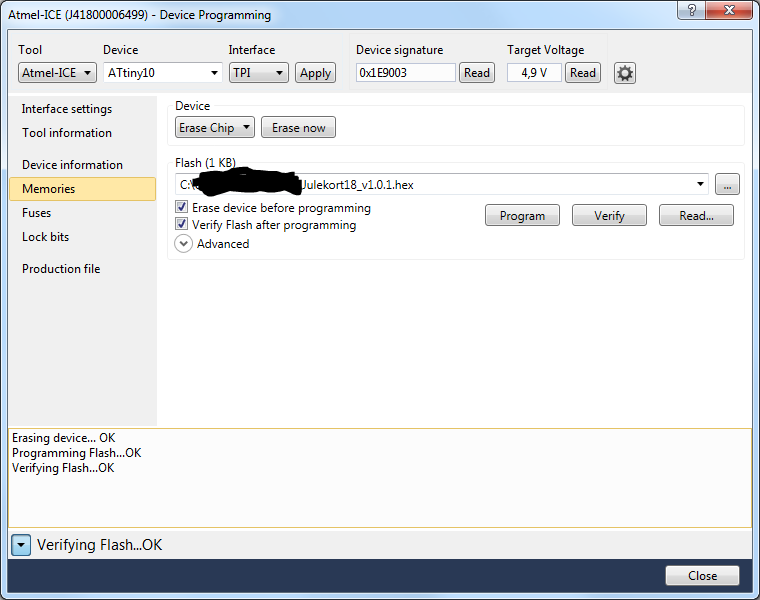
How to program it?
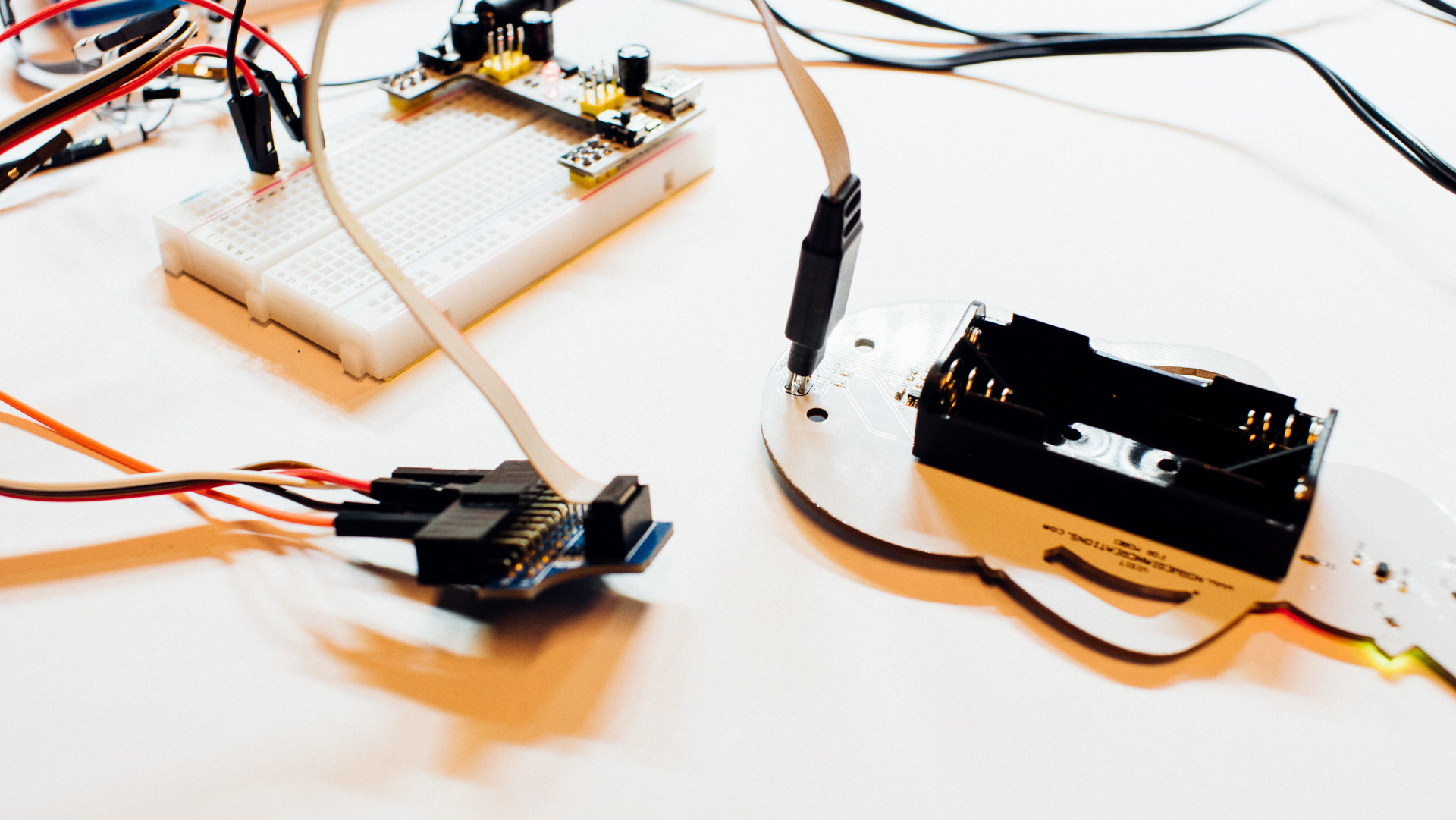
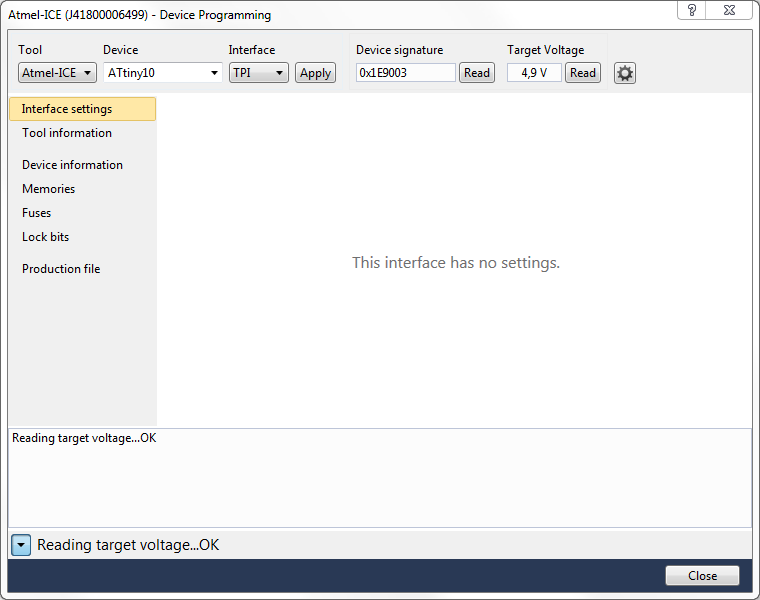
We programmed the ATtiny10 using TPI. Note that the programming voltage has to be around 5 volts. The circuit can handle it, but the batteries does not supply that, so an external power sourcing solution has to be implemented.
Do that without batteries beeing inserted.
We used the P1 header, a TC2030-CTX-NL tag connect cable, an adapter for just making it easier to connect into the 50 mil header on the cable, an ATMEL ICE, and a “breadboard PSU” we had lying around.
We tied things together with a small breadboard.
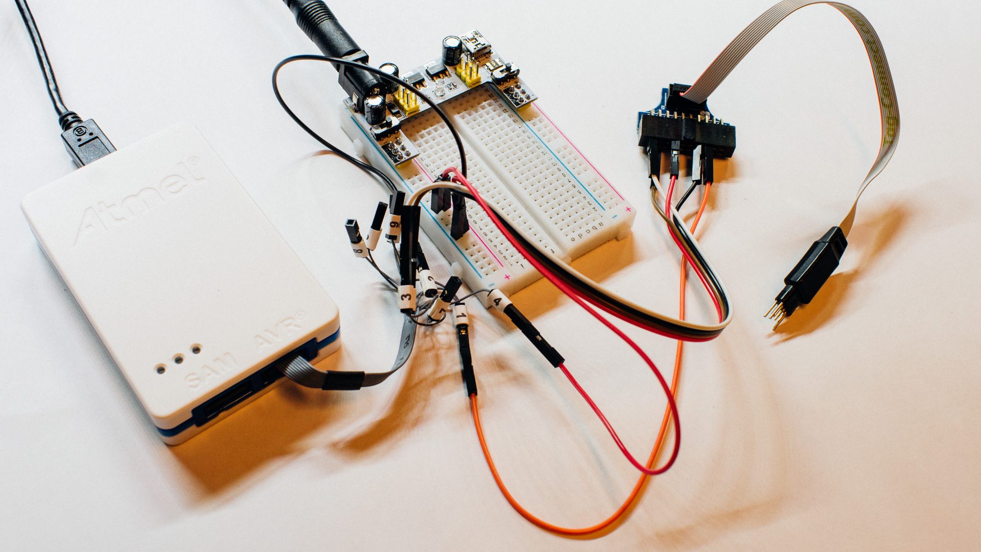
On this breadboard we pulled out the 5 signals of interest from the tag connect and connected them to the programming tool. We placed the small power supply on the breadboard to make it easy to supply 5 volt to this programming system.
The “mini squid” cable from the ATMEL ICE was used to connected the different signals according to the pinout given here.
Signal – Mini-squid pin
TPICLK – 1
GND – 2
TPIDATA – 3
VCC – 4 // Note that this does not supply the card!
!RST – 6
We did the programming through Atmel Studio.
But what does the firmware do?
- It holds the unit in deep sleep until the button is pressed.
- After it’s pressed, it blinks the LEDs and holds them on for approximately 12-14 hours. Then it turns them off and goes back to sleep. Thereafter, it goes back to the start…
It’s possible to shut it down by pressing the button when it is in this ON-state.
All “timing” is done using the watchdog timer.
Most of the energy should be used to drive the LEDs!
The Stand
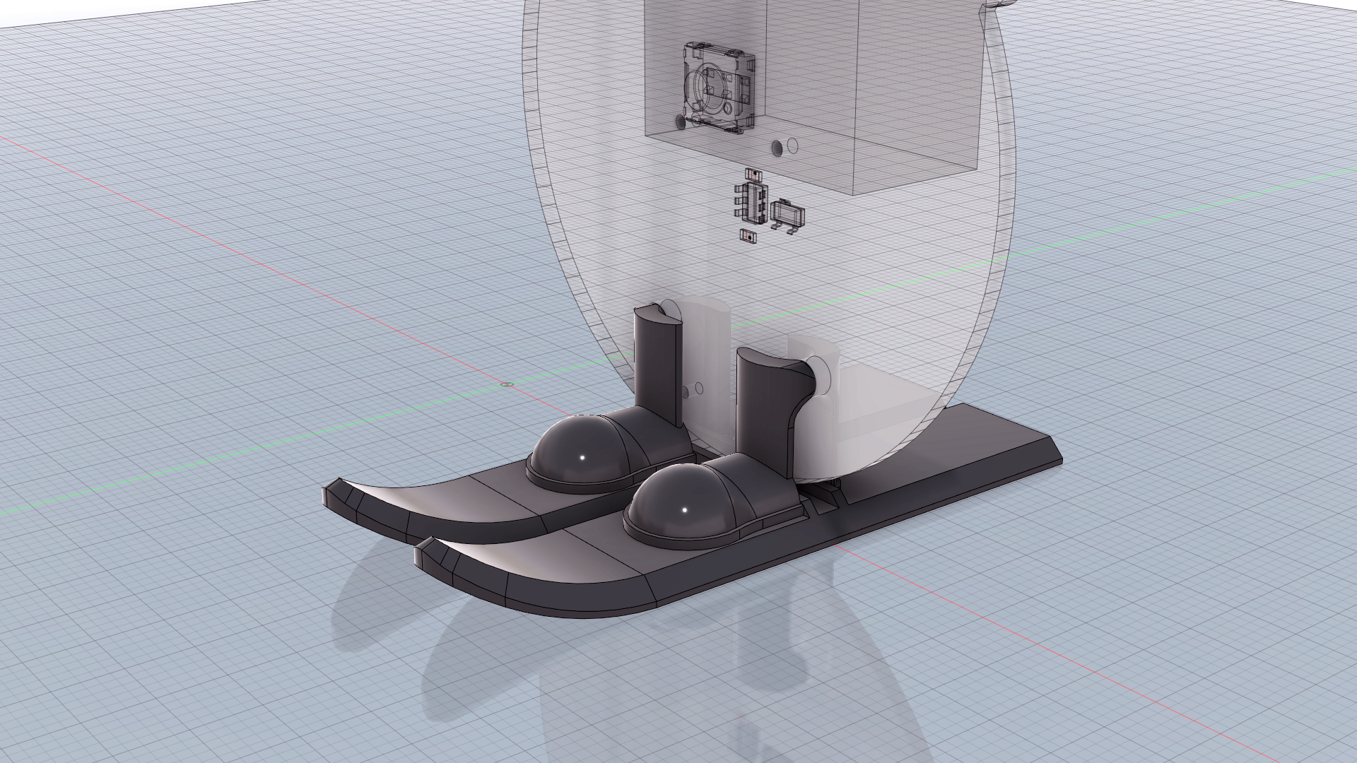

We modelled the stand as skis and 3D printed them in house.
You can print one yourself with this STL file.
The Result
An early “Merry Christmas and a happy new year to all our blog readers”!