A few months ago we wrote a blog post about a course in embedded systems for beginners where the goal was to make Space Invaders on an embedded system. We thought it would be fun to create a casing for this such that it could become hand-held, almost like a Game Boy.
Casing Design
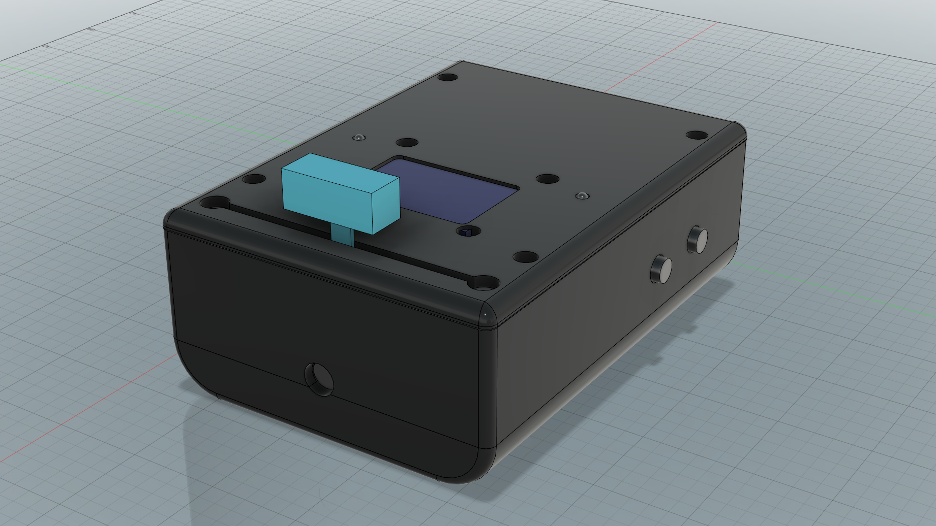
At first glance (and probably a few successive ones as well) this design is straight up comical. But there are reasons for it.
Ergonomics
The potentiometer slider requires some force to be moved and therefore it is not sufficient to place the device on the table and rely on its weight to keep in place. The player will need to use the other hand as a counter-force when moving the slider. So we thought of a way to play where one hand is holding the device and the other hand is moving the slider. The hand holding the device then needs to operate the two buttons.
Ergonomics-wise, the end-results is pretty good. The device feels good in the hand and it’s easy to manipulate all the control inputs.
The Thickness
The first thing that slaps you in the face with this design is the silly thickness of the whole thing.
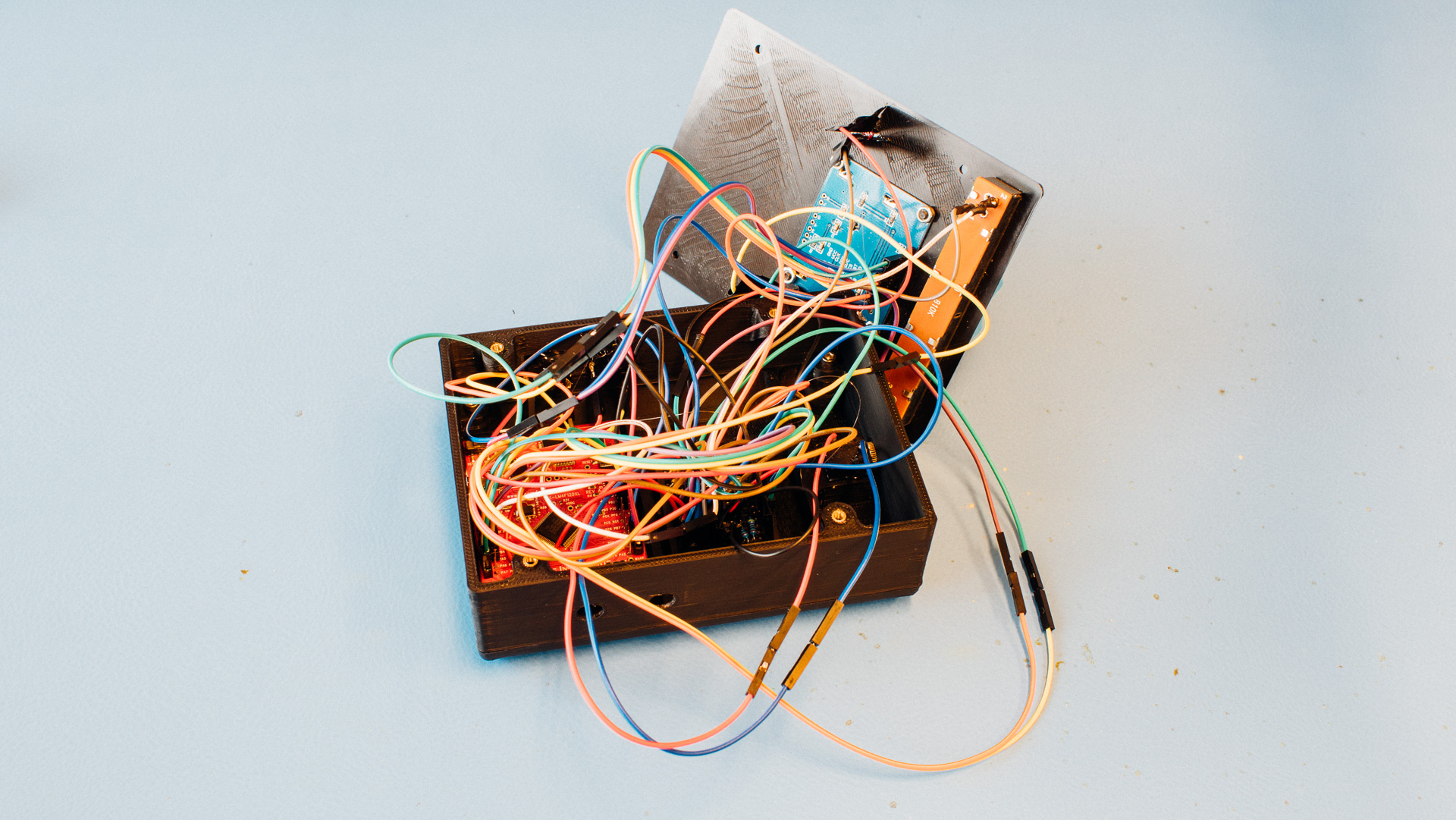
We wanted to continue using the wiring method as seen the previous blog post. This means lots of jumper wires, a breadboard and not much soldering. This requires a lot of space in the height axis. If we would’ve soldered wires directly onto PCBs and not used a breadboard we would’ve saved a lot of space.
Length and Width
The width is limited by the length of the slider used, and preferably it would’ve been a bit narrower. The length is not that critical. We’ve tried to make as short as possible without complicating things too much.
General Casing Stuff
Due to the usual gravity-related FDM printer challenges, and our desire to avoid too much support, we’ve split the casing into three parts: top, side and bottom.
We use M3 brass inserts to achieve nice threads for the screws connecting the 3D printed parts together.
The bottom has a few “beams” across the body. This is to limit the support area during printing since this can lead to unwanted results and/or failed prints.
Components and Mounting
First, the larger breadboard from the initial project was swapped out with a much smaller one (around 46×35 mm or 17x(4+4)) pins. These breadboards have a double sided tape underneath, making them easy to mount to a flat surface. The PCB was also fastened to the casing with double sided tape.
The buttons are regular push-buttons (12×12 mm) which were hot glued to the casing. The audio jack port was also hot glued to the casing as well as the LEDs.
The LCD display and the slider (~88 mm long) was mounted with M3 screws to the casing lid since these already had mounting holes.
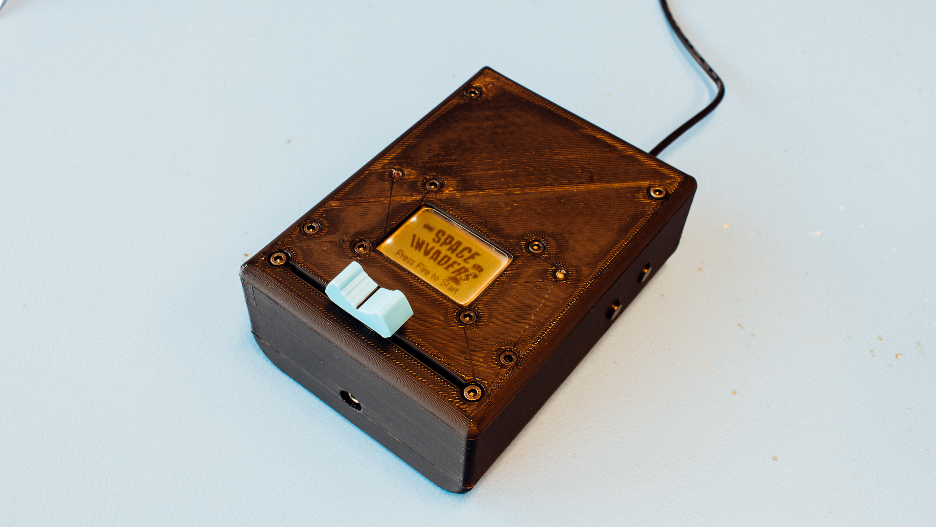
User Interface
Closest to the user we’ll have the slider. Just above it, in the same plane, we have the LCD display. This could’ve been placed further up the front face for a more traditional hand-held gaming device look, but due to cable management considerations this was placed close to the slider instead.
The side part will have two sets of button slots such that the user can choose whether to hold the device with the left or right hand. On the front side of the device we’ll have the audio mini-jack port and on the back side the USB power will be connected.
Files and Summary
If you have completed the same embedded systems course and want to make your Space Invaders game hand-held, you can find STL files for the project here.

This work is licensed under a Creative Commons Attribution-NonCommercial-ShareAlike 4.0 International License.
Just beware of the high spaghetti factor when transitioning from the initial breadboard project. It might be a good idea to look at alternative solutions such as soldering directly on the PCBs.