About a year ago we bought a Prusa i3 printer from Geeetech. At the time, it was probably the cheapest printer on the DIY market at 249$. As expected, the printer had several areas which needed improvement. In this blog series, we will go through how we improved the printer in several ways until it could print acceptable parts.
In this first post we will look at part cooling, which is very critical when printing PLA and some other materials. Our printer did not have any form of part cooling when we got it, so we had to create our own solution.
Existing Solutions
Our first thought was of course to hit up Thingiverse and similar sites to look for some pre existing solutions. We quickly found some simple fan mounts made by JimmyShawsTidbits.
This cooling solution was way better than nothing, but it only cooled one side of the prints. When printing a 3D Benchy boat, we saw that one side had perfect overhangs, while the other side was messy.
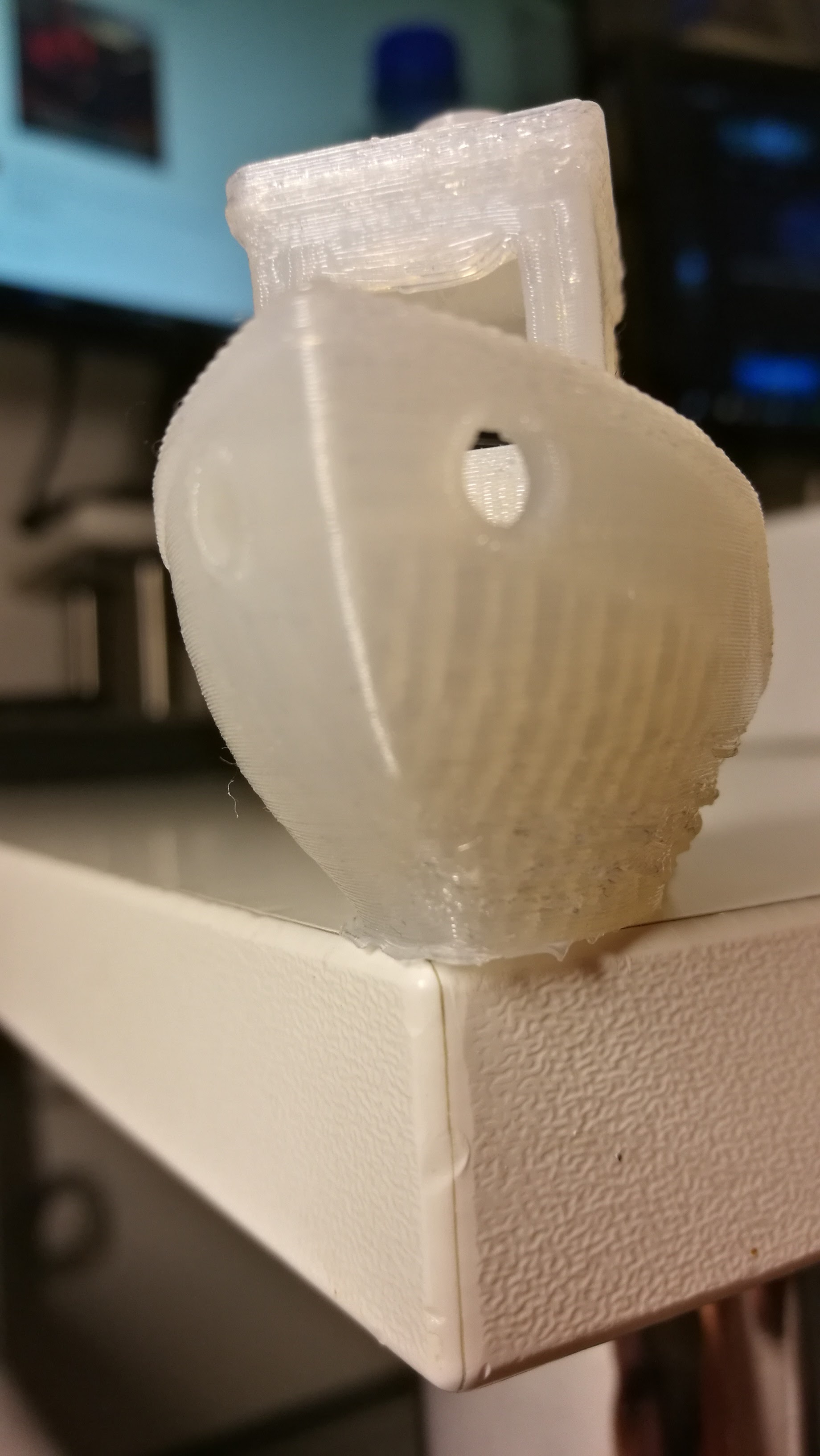
We found a hinged mount which we used to mount another fan behind the X axis carriage. This gave us cooling on both sides! The fan behind the carriage was not optimal on the other hand. Firstly, it was pretty far away from the hot end. Secondly, it was crashing with both the printer frame and cable management in the back of the printer.
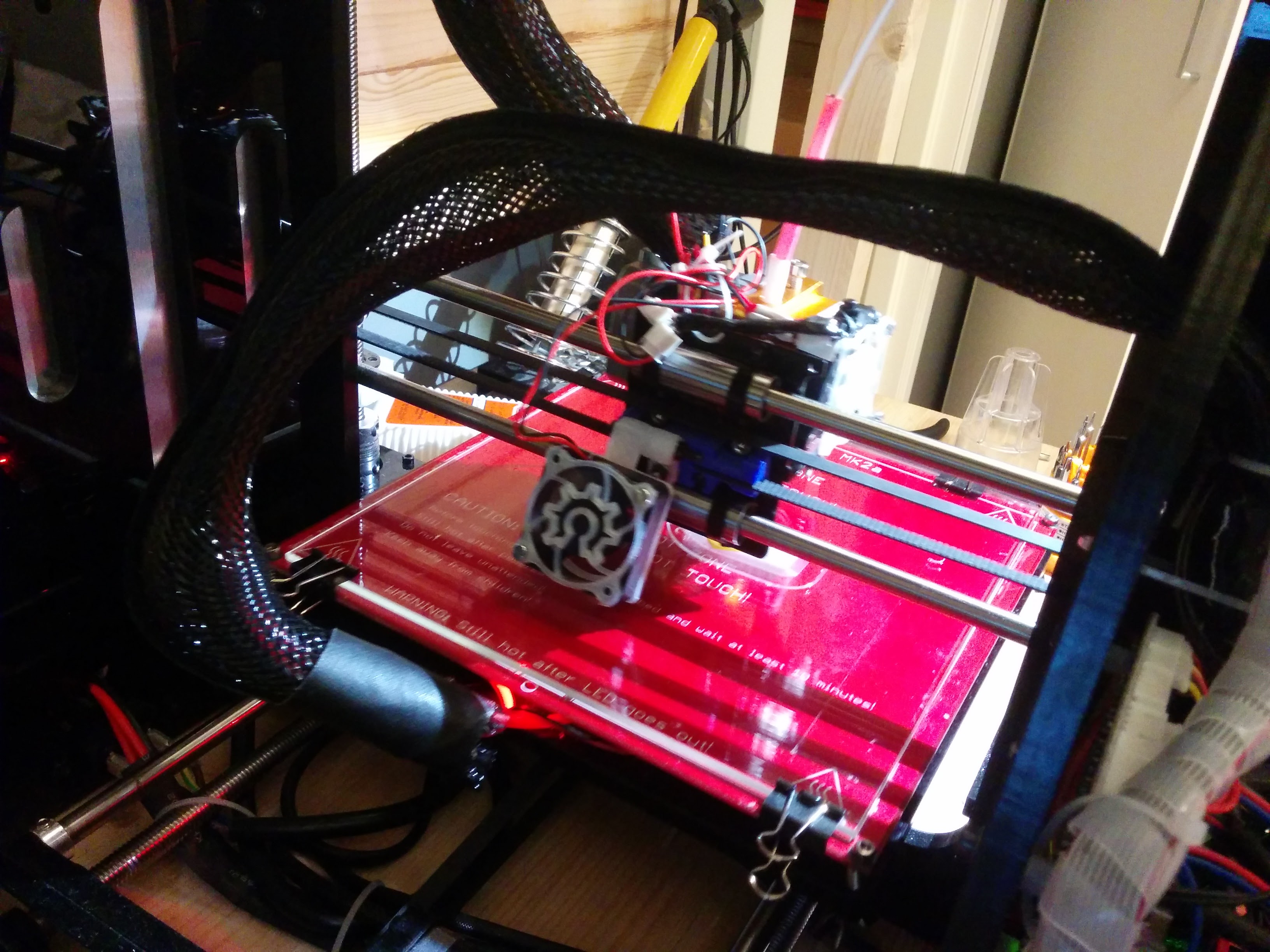
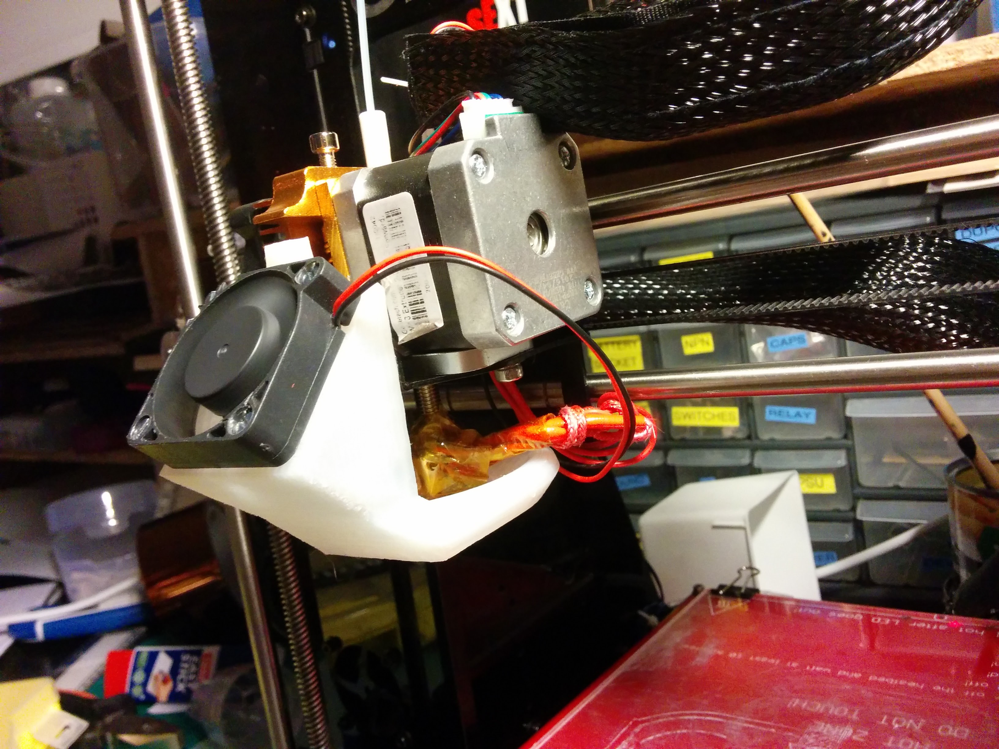
We then found some resources online suggesting that a circular cooler was the best. This type of fan shroud cools the extruded plastic from all sides right after it is extruded. We found a design on thingiverse for our printer. The first challenge was to fit the ring around our hotend, which we had to turn 180 degrees to fit. Our next challenge was that the airflow through the fan shroud was extremely low. This can partly be explained by the weak 40mm fan we used at the time. The shroud has very narrow insides that the air has to flow through, and we recommend using a fan with more “pushing power” than what we used (like the ones used further down this post). The challenge that made us walk away from this type of shroud, was that the hot end was virtually inaccessible for cleaning and adjustment when the shroud was on. Since our printer is VERY sensitive on Z axis adjustment, it is important that we quickly and easily can level the bed.
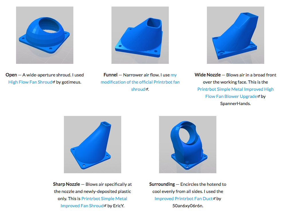
We then discovered this great writeup on fan shroud types over at desiquintans.com. The conclusions there were that cooling focused narrowly where the plastic was extruded gave the best results. Everyone thinking about improving cooling for PLA should read that article before doing anything.
Custom solutions
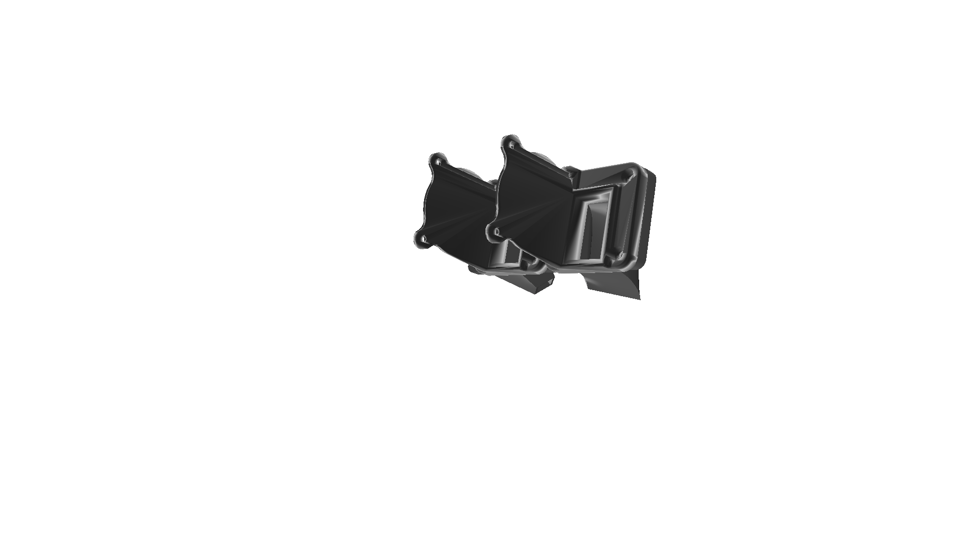
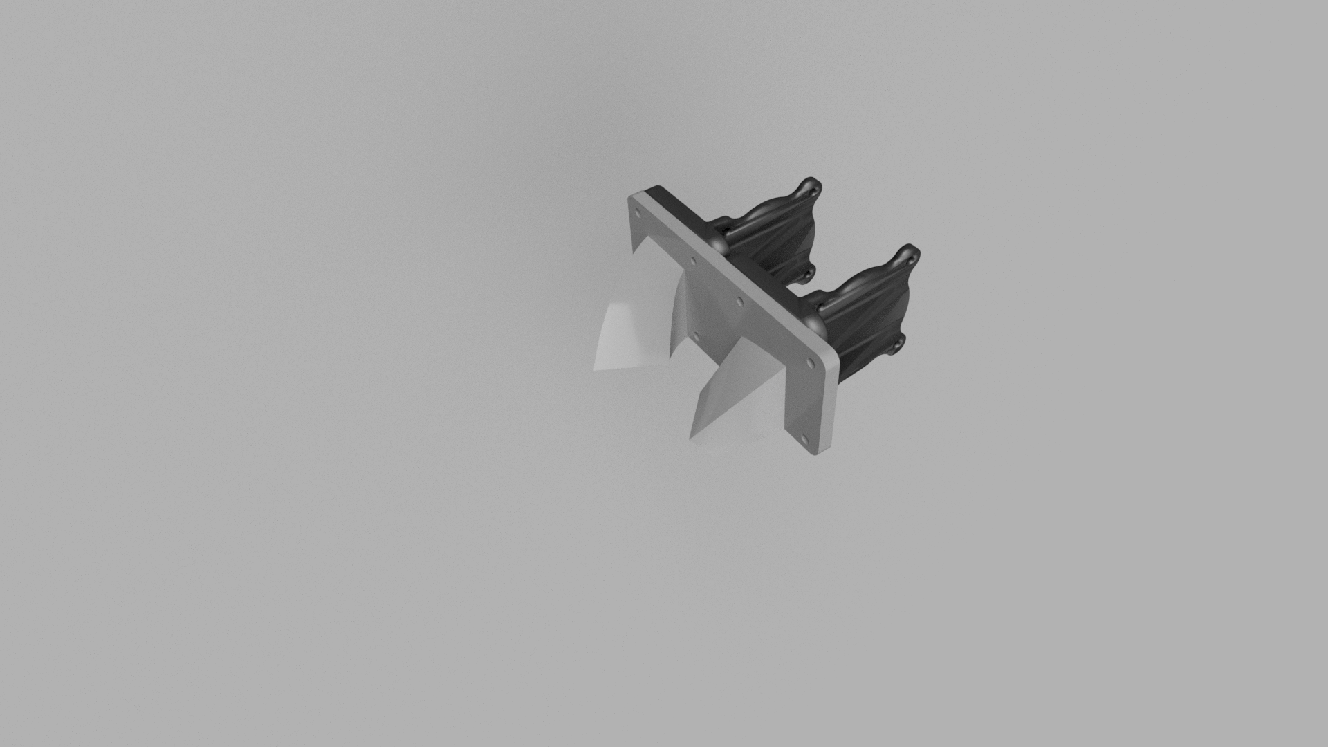
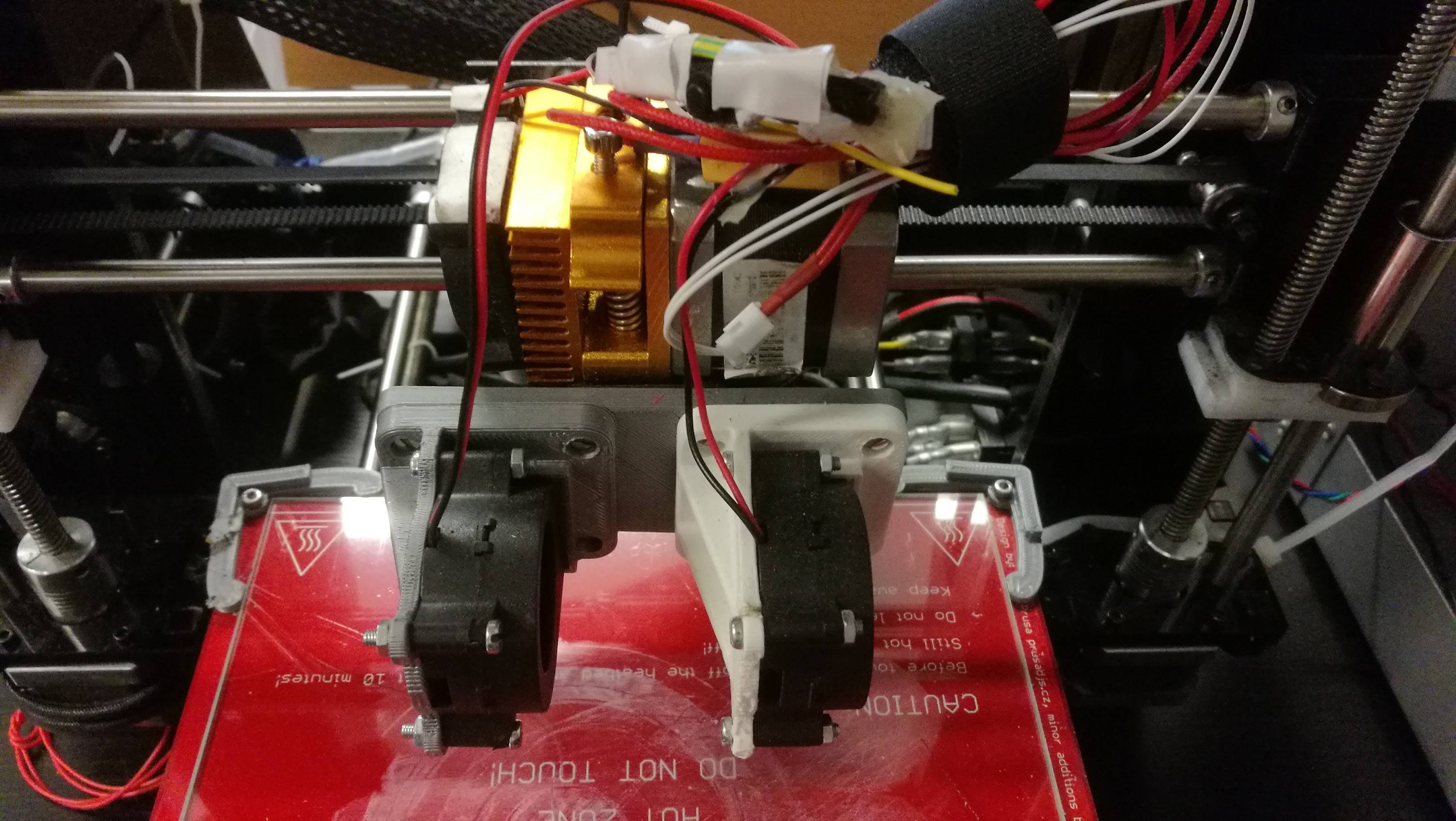
The article also concludes that one narrow fan shroud works great together with one fan which blows a wider airflow through the print. We opened up our go-to CAD program Fusion 360, and got to work on designing a fan mount and shrouds. We came up with this bracket solution which allows fine tuning of fan shroud height and angle. It also allows fan shrouds to be easily replaced by other designs.
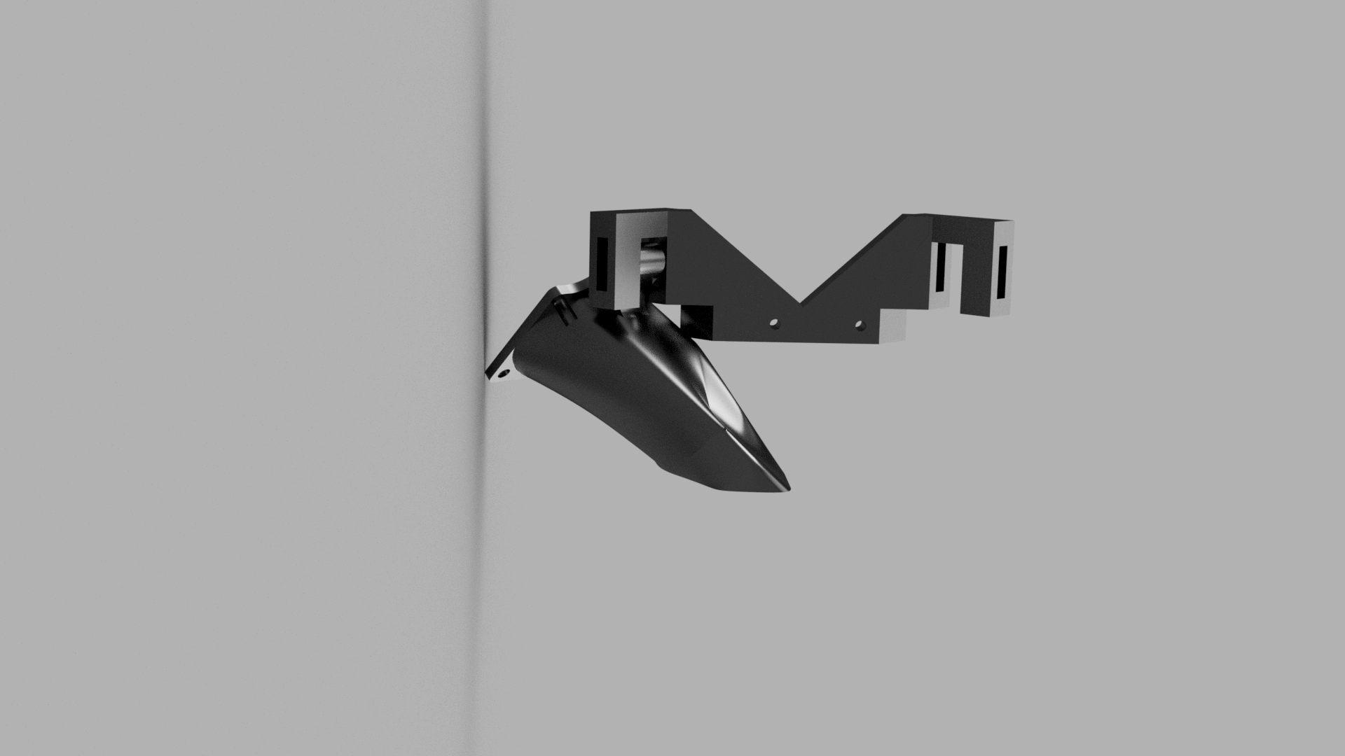
One downside of this design was that is was all mounted in the center. Since it became very wide, it contributed a significant amount of inertia to the extruder block. The entire construction became very shaky and vibrations became very apparent. The other downside of this design was the same as with the circular shroud. The hot end is harder to access for cleaning and adjustment.
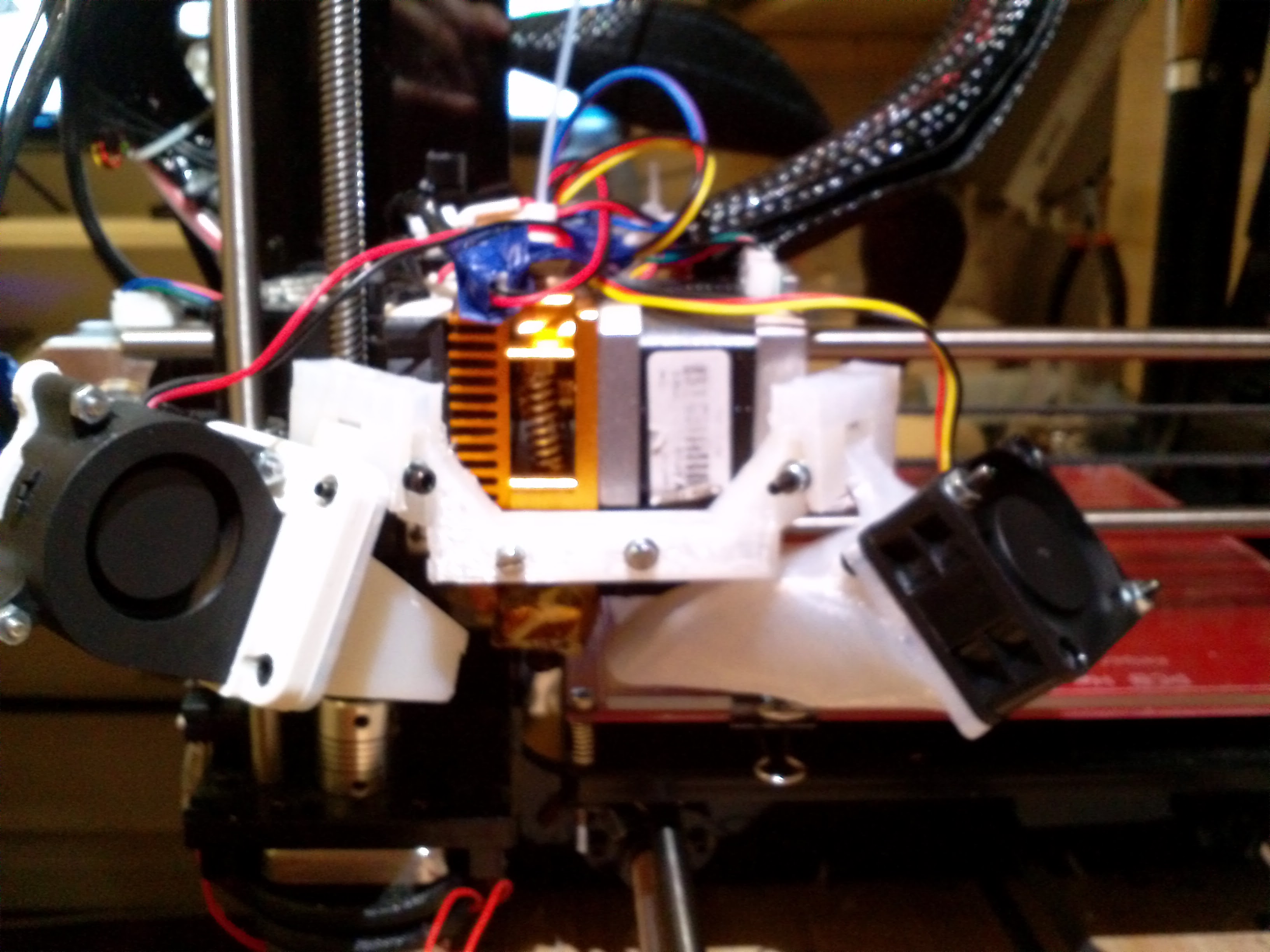
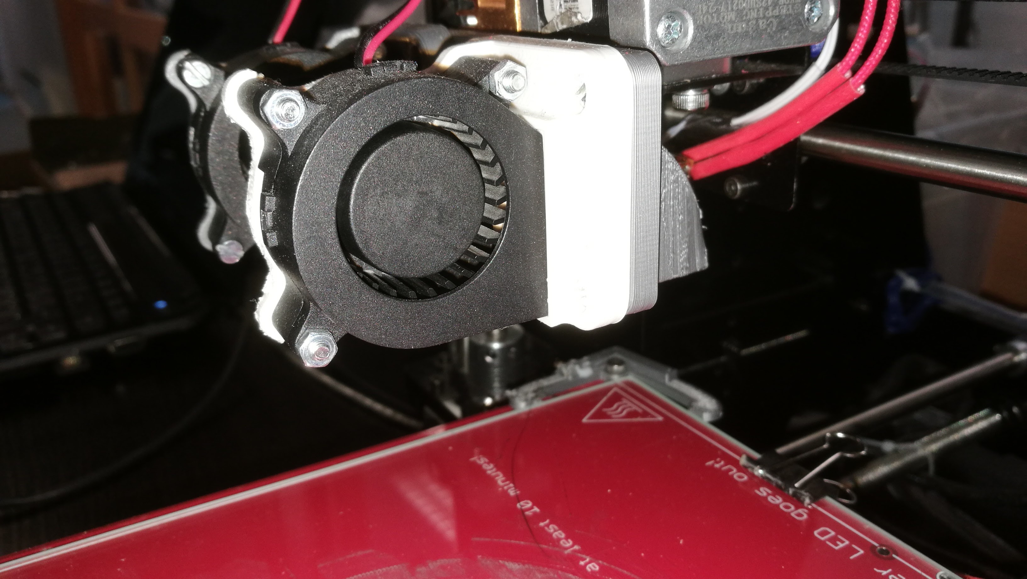
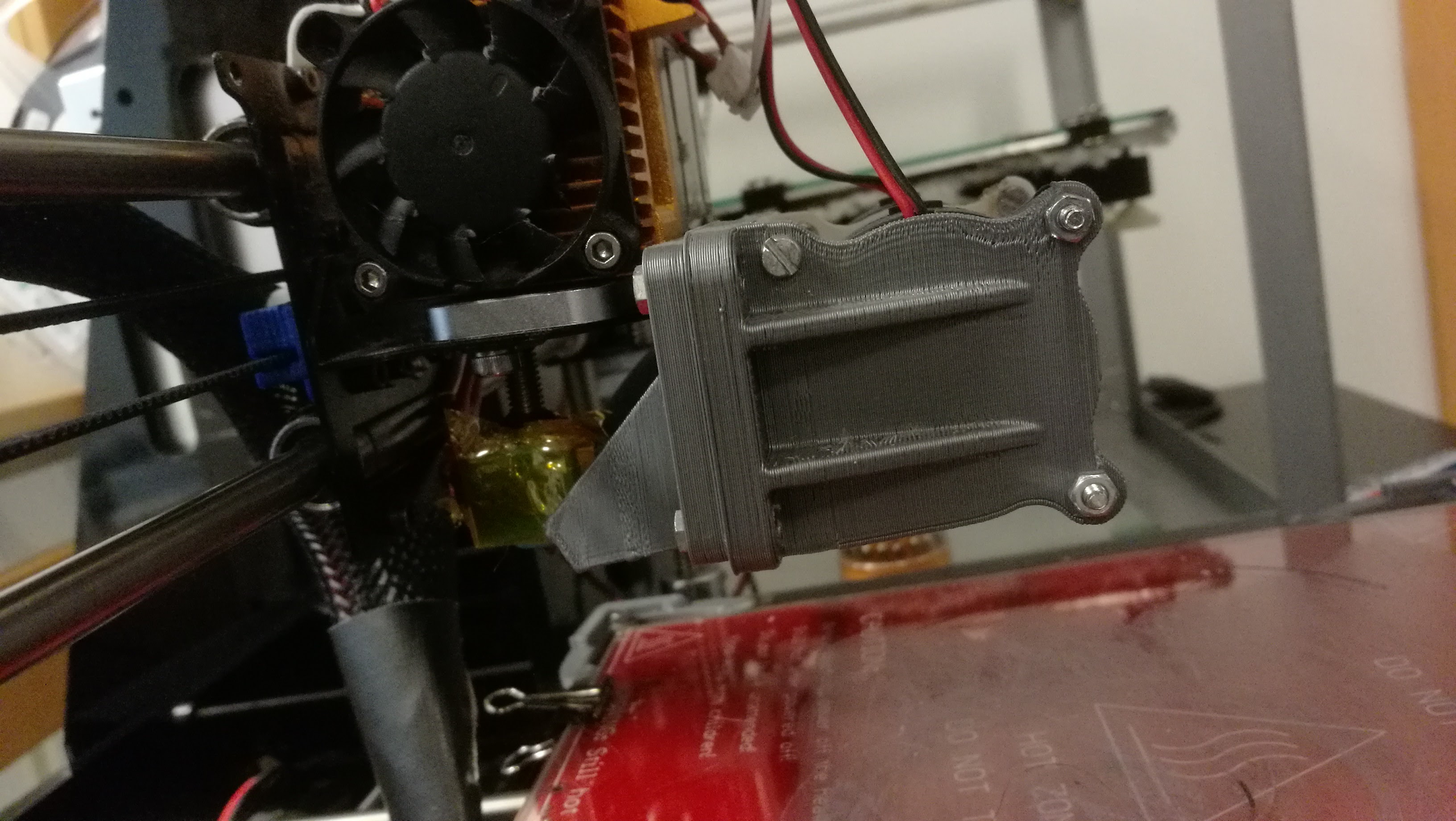
Our last fan shroud revision is an improvement on the previous one. It has a more compact design, and is easily mounted and dismounted from the X carriage. It is designed for 40mm radial blower fans, a fan type which excels at “pushing” air through pipes and shrouds. The fan shroud is one part, which attaches to the X carriage. We are using a 40mm Axial Fan to 40mm Centrifugal Fan Adapter found on Thingiverse to attach our radial fans to the standard 40mm fan mounting holes.
Testing
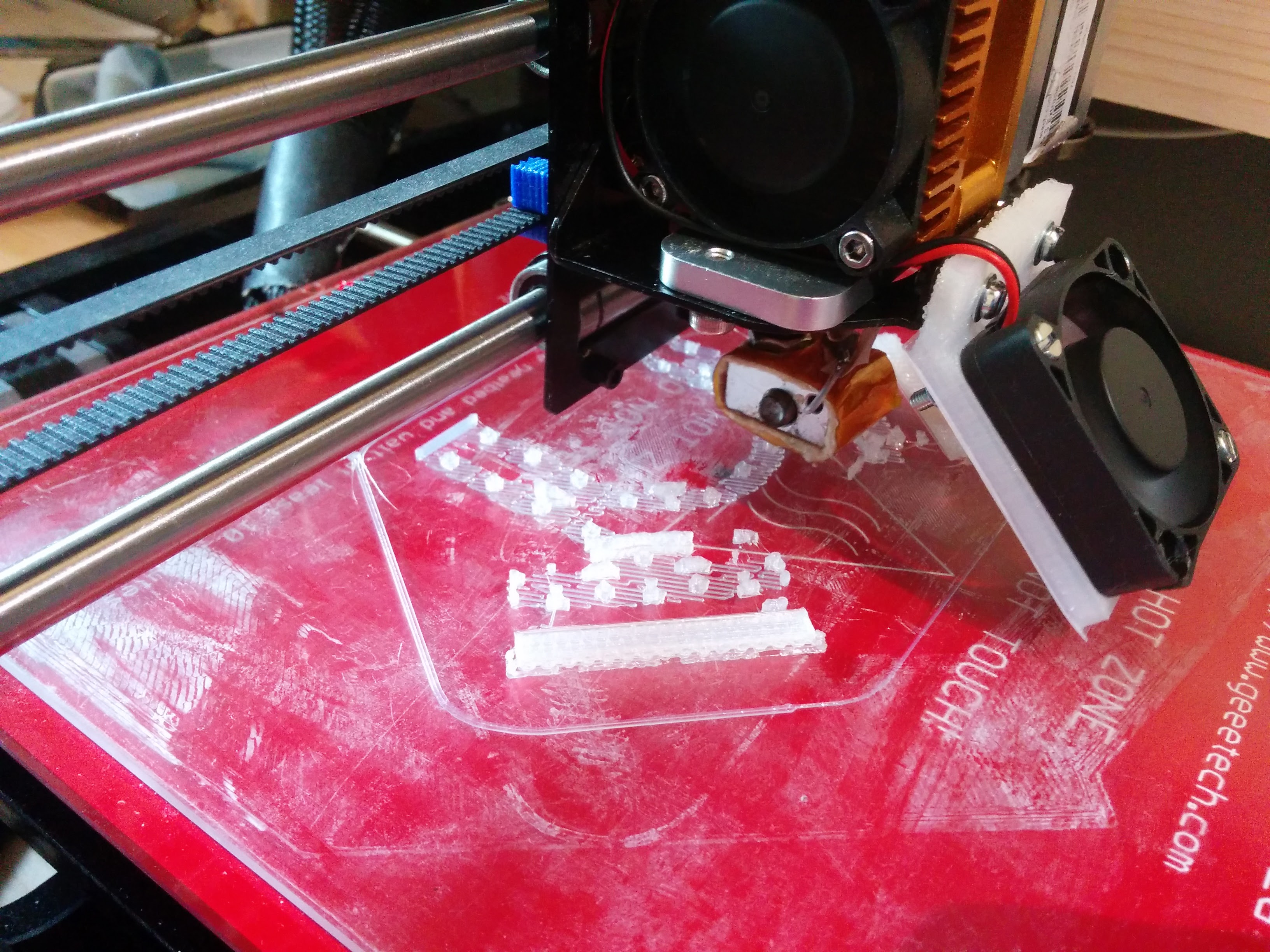
After mounting the newest fan shroud, we did some test printing with the cooling both on and off. The first test we did was a 5mm diameter tower, which ends in a sharp point at the top. This is a good test for cooling, since it is critical that the previous layer has cooling before applying the next one. Some slicers has a setting for a “minimal layer time”, which would make it pause between each layer in this print. We did not use such a setting when doing these prints, in order to see the difference better.
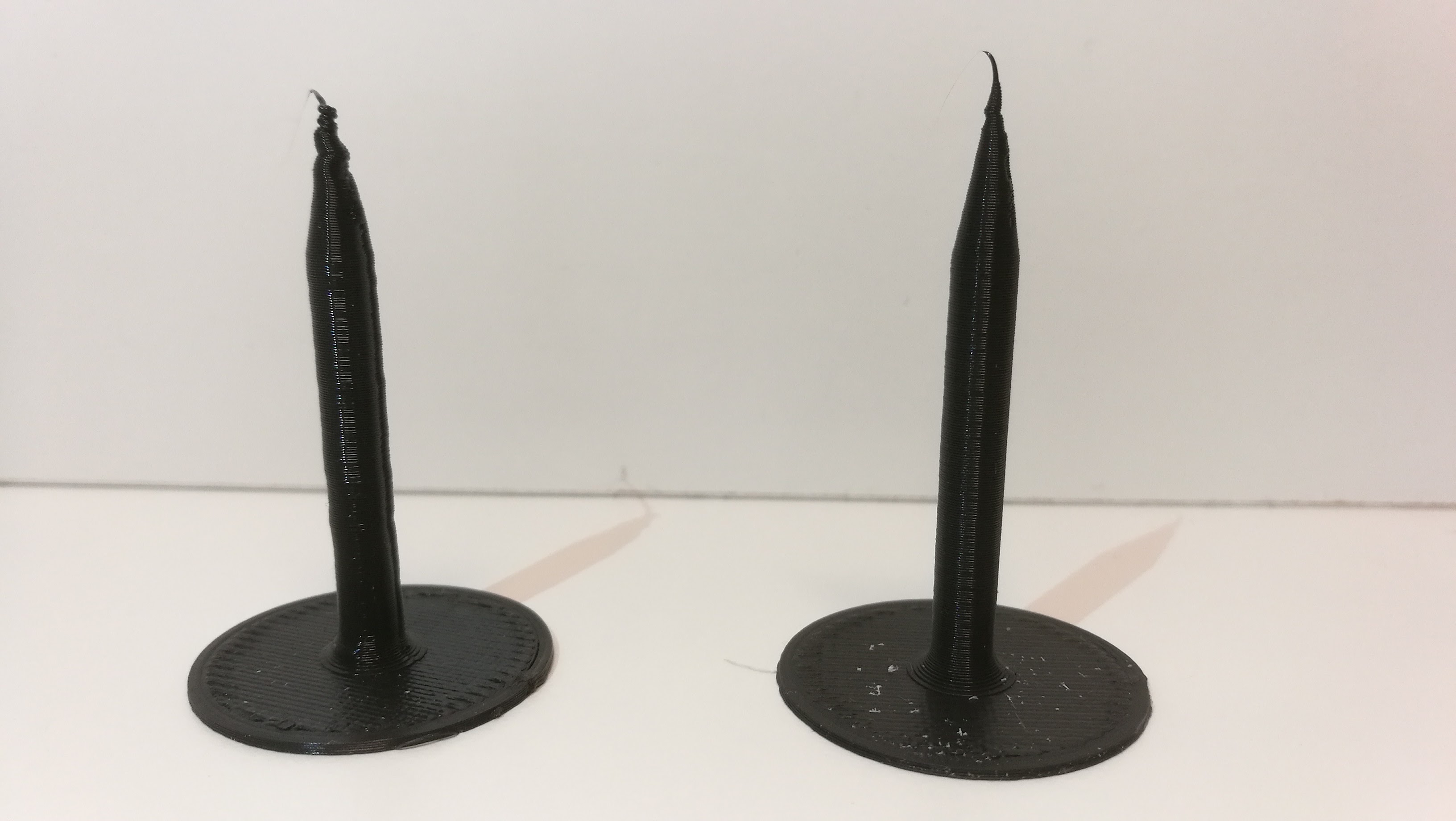
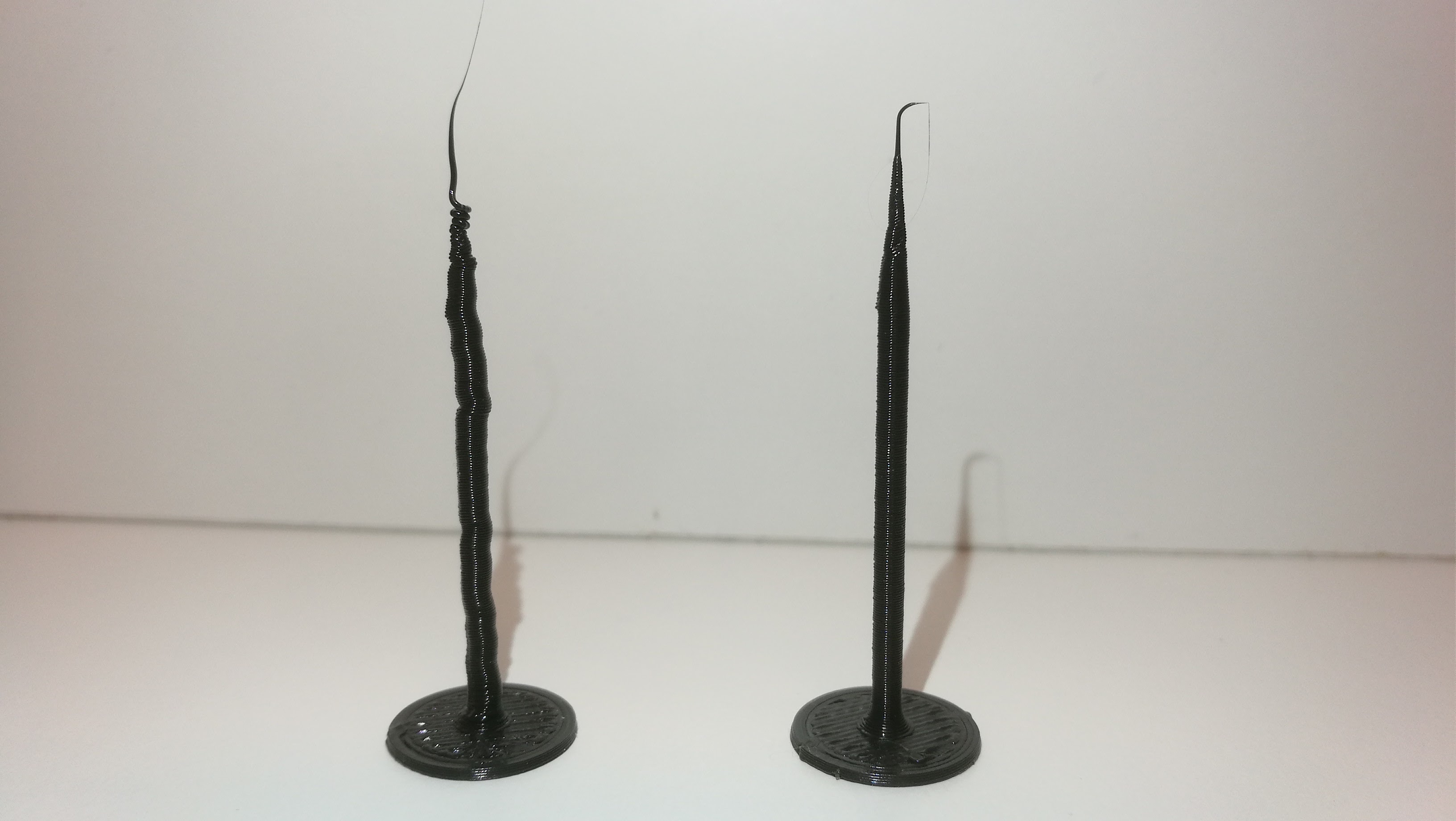
We did not see the extreme difference we were looking for, so we scaled the model down to hald thickness to make it a bigger challenge for the printer without cooling.
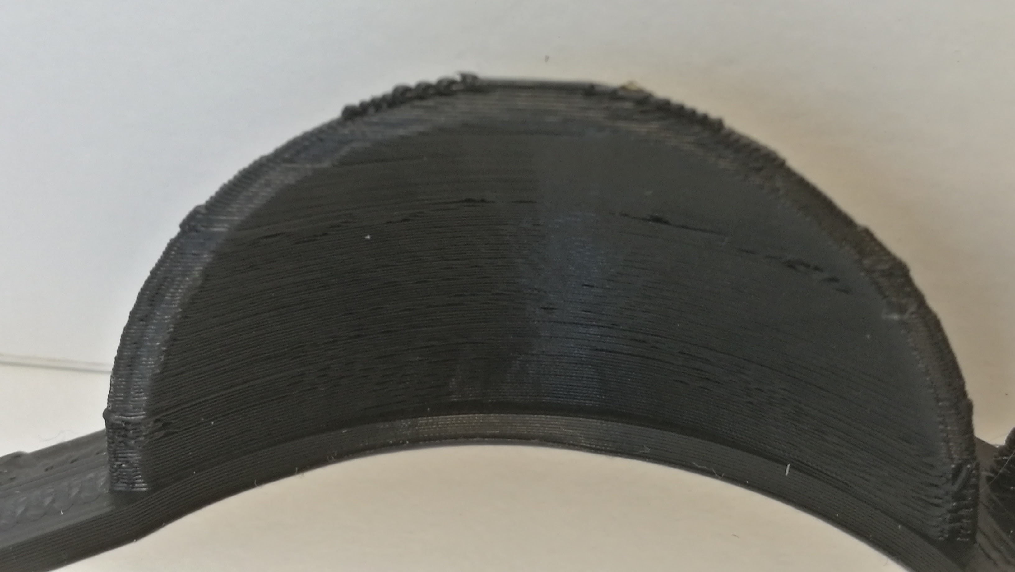
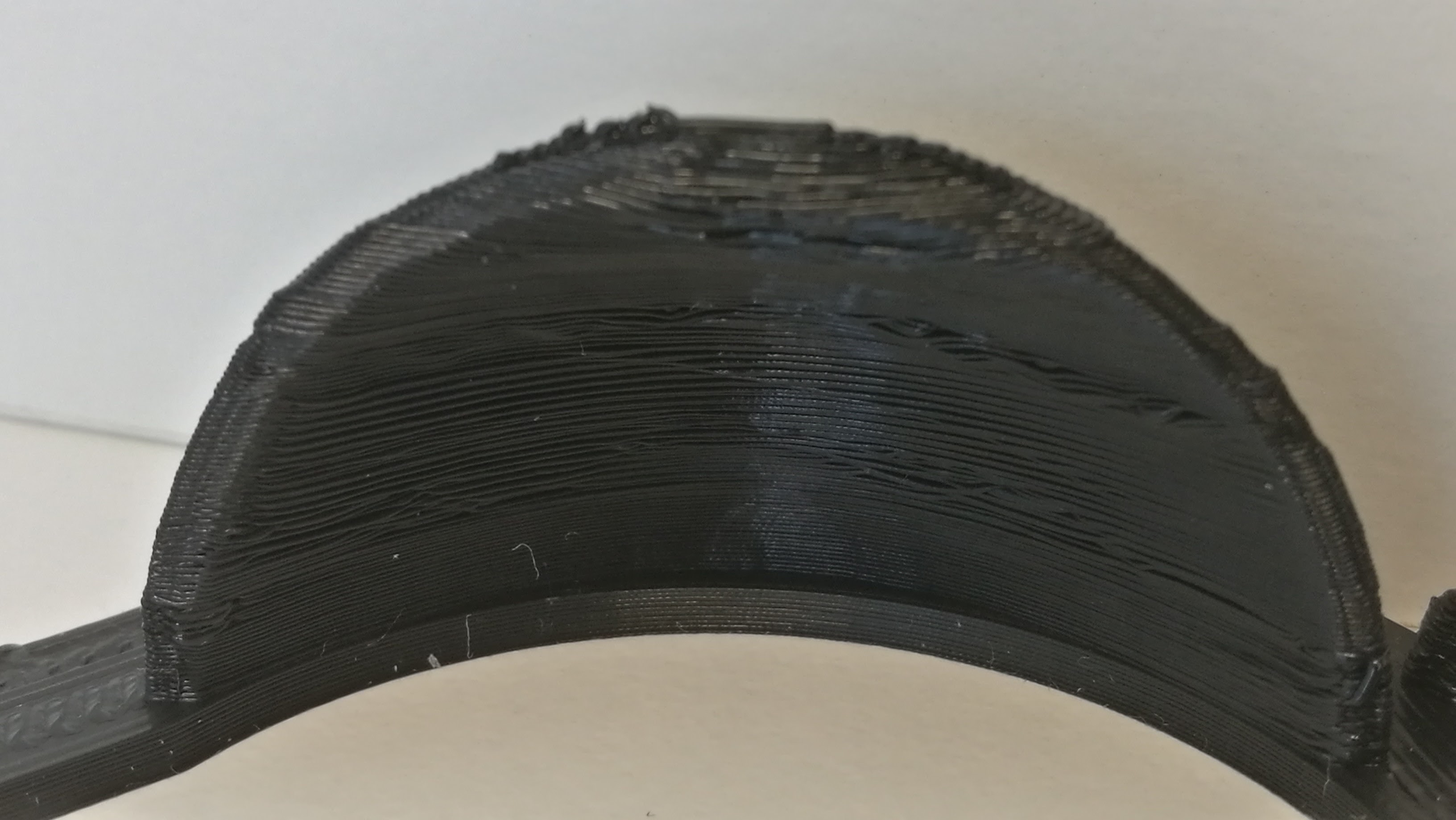
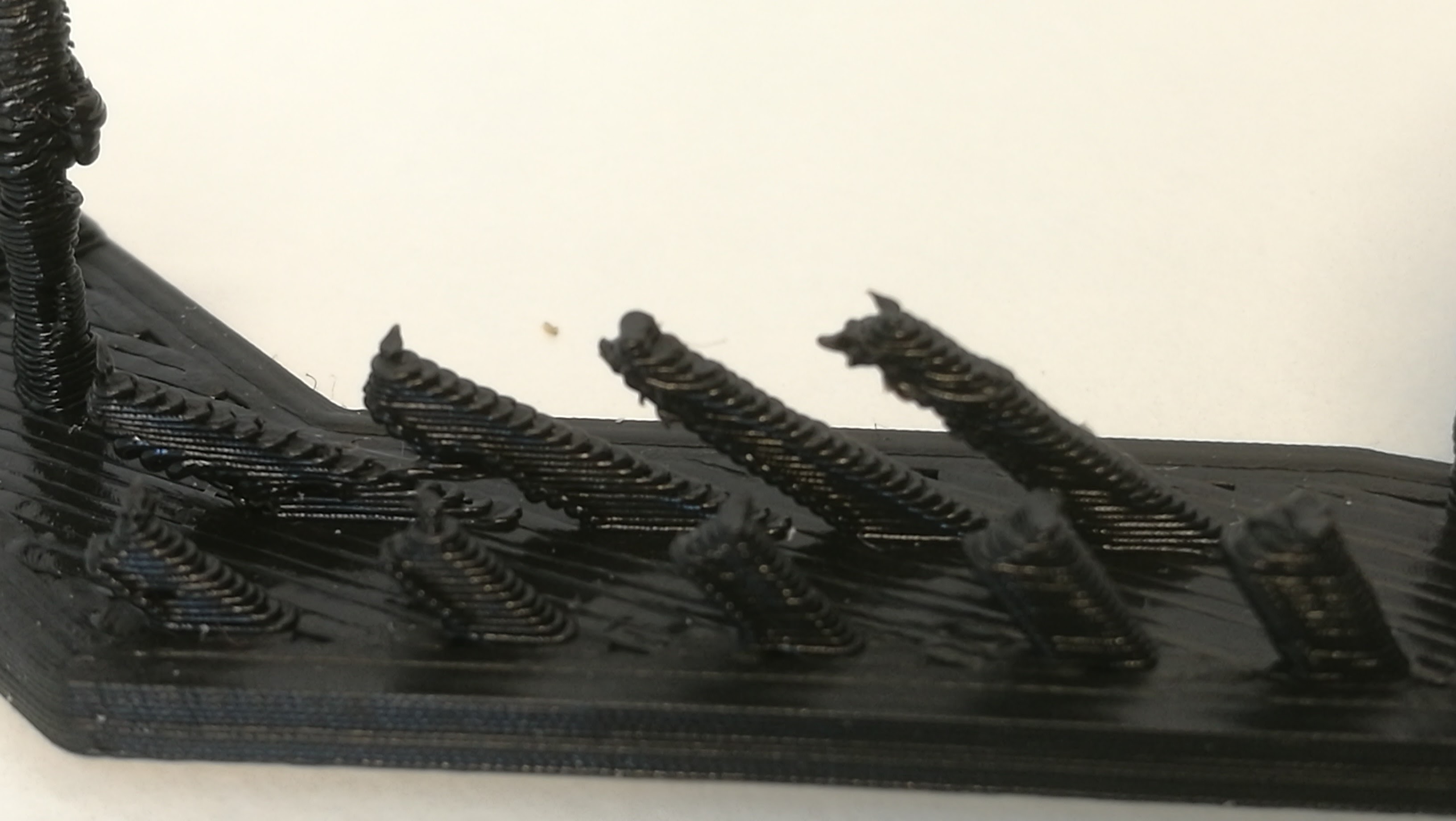
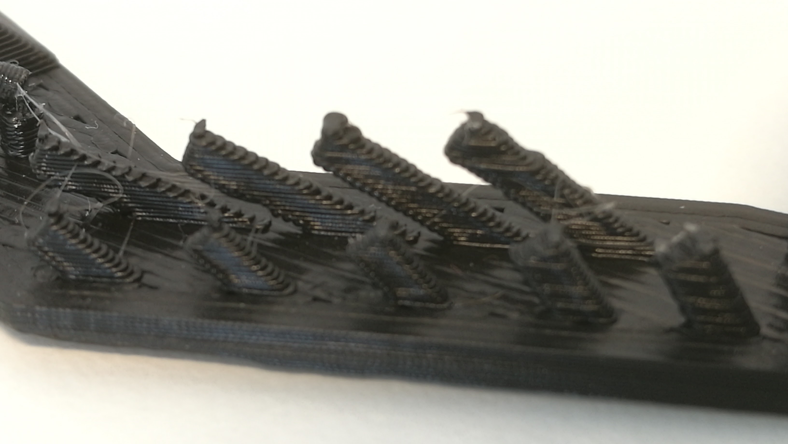
We also printed the ctrlV v3 printer calibration print with and without the cooling on. The difference is most clear in the parts containing overhangs. The half dome and overhang “spikes” came out much cleaner with the cooling on. Surprisingly, the tower came out much worse when the cooling was on. We have no explanation for why this happens, as it is quite counter intuitive. The bridge part was straighter and had less “blobs” on the cooled version. The largest hole was measured to 4,4mm diameter on the cooled version, and 4,2 mm on the non-cooled one. This shows how a the non-cooled plastic will “bloat” out a bit before becoming stiff. This is the same effect that makes corners less sharp without cooling.
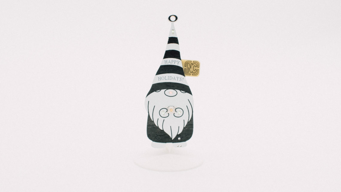
In this post we have looked at some cooling solutions for the cheap Prusa i3 printer. The latest custom fan shroud we have created can be found here.
In the next couple of posts we will tackle issues like Z axis wobble, inconsequent bed leveling, and problems with cheap extruders.