Last year we made a small laser engraver, aimed toward creating small engravings on wood. It worked, kind of.
With kind of, I mean some features could have been better:
- Size: The last one had only a 2.5cm x 2.5cm work area. Way to small.
- Usability: We had created a quick and dirty script for converting images into engraver commands. This script only partially supported vector graphics, which is a must for laser engravers.
- Safety: with a 2W laser diode, serious damage can happen! Our safety routine consisted of a timed delay, and a walk of of the room. Yeah. Not good enough.
Therefore; the new machine will be:
- More user friendly: It will support the standard CNC machining language: G-CODE.
- Bigger: It will have a working area of at least 40cm x 40cm.
- Safer: It will be totally boxed in, with a safety approved laser glass window.
And it will be a nice way to learn how to create parts using our Solidoodle 3D printer.
Jump straight to the next part showing the finished laser engraver in action here!
The first mechanical design attempt
In the CAD everything looked great. Nice rendering and beautiful colors. Every not-grey-part was going to be 3D-printed.
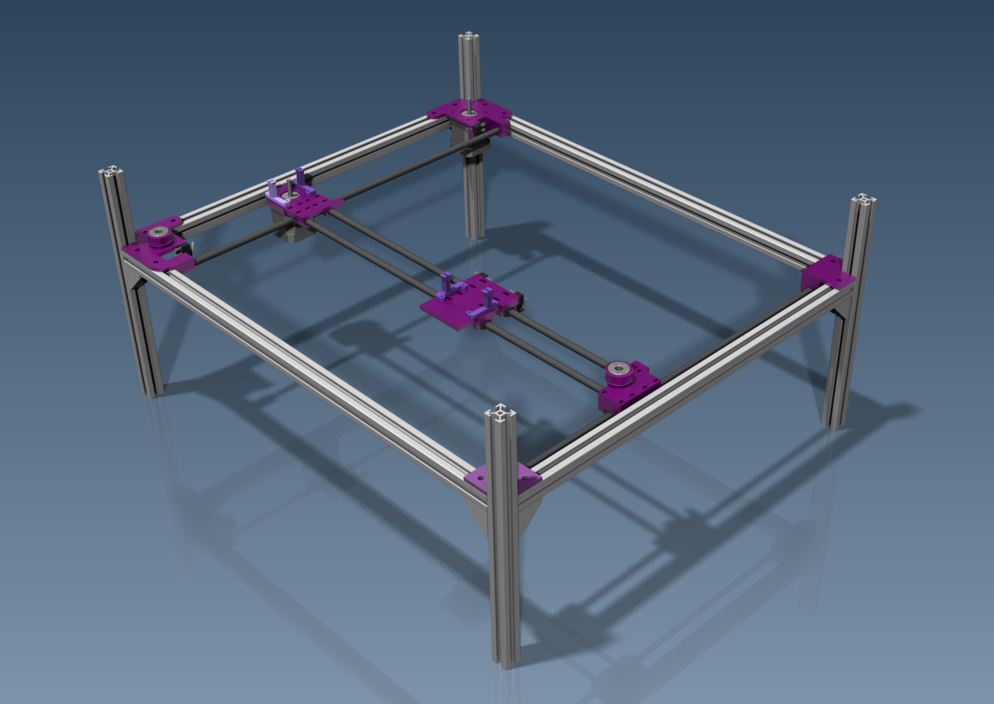
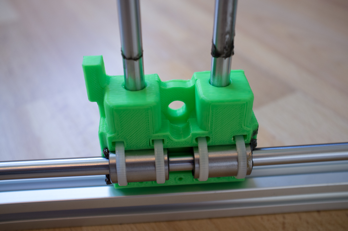
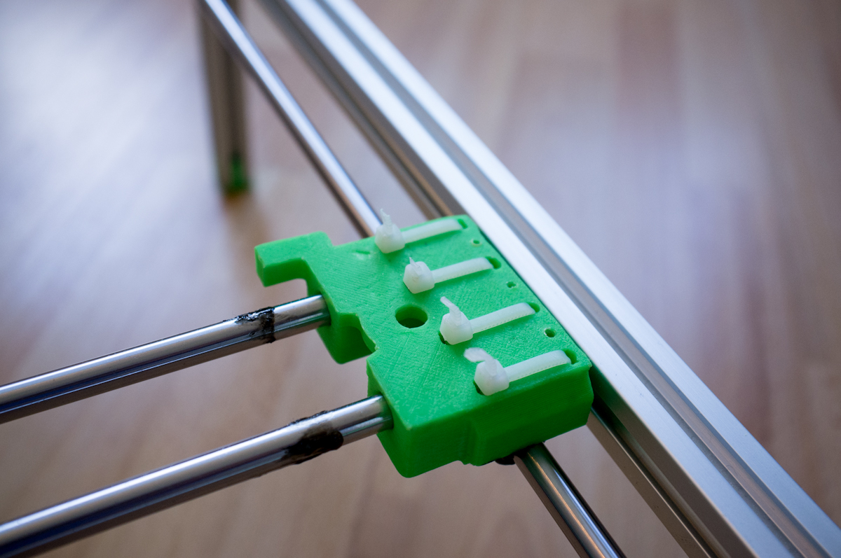
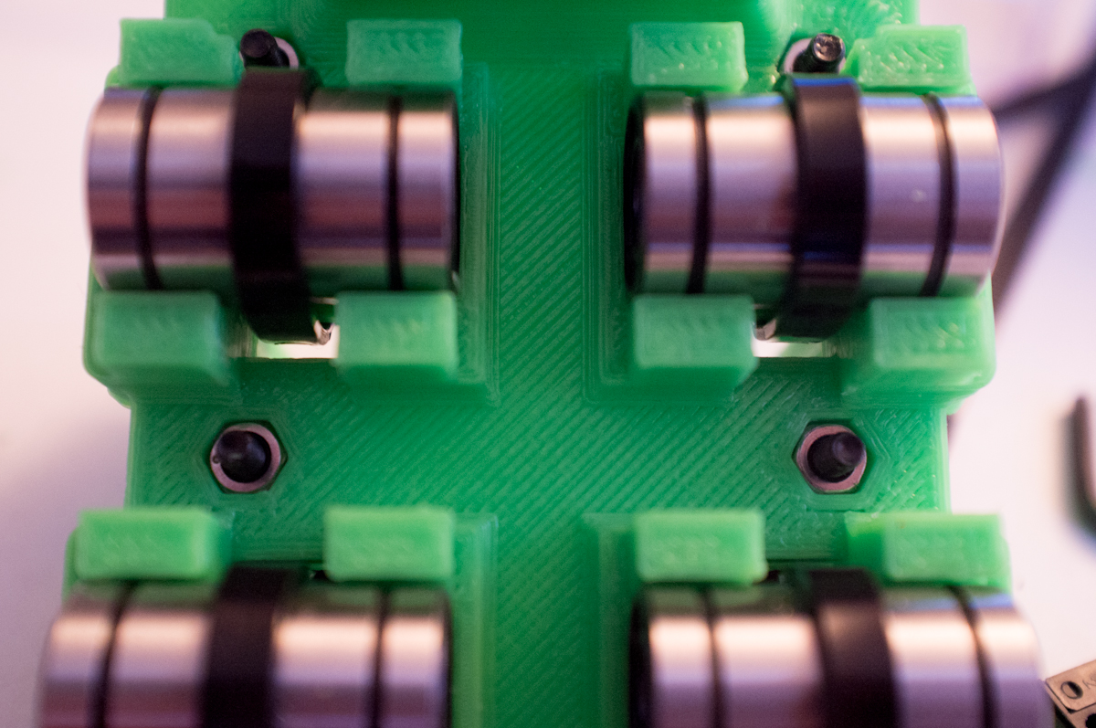
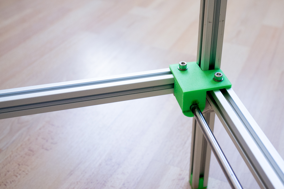
After several hours printing, failing, re-designing, printing, thinking, redesigning and printing again a lot of green ABS had been used. And the first mechanical concept had been created.
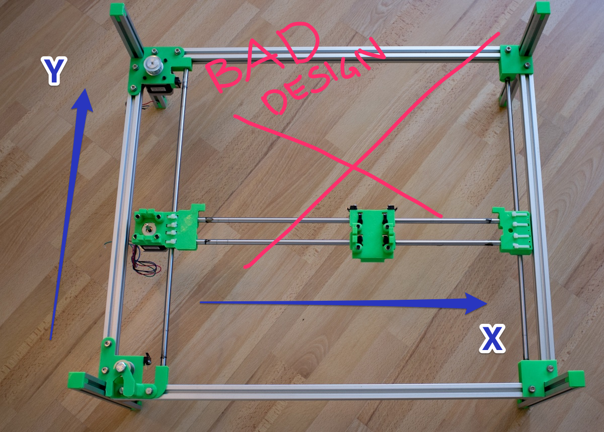
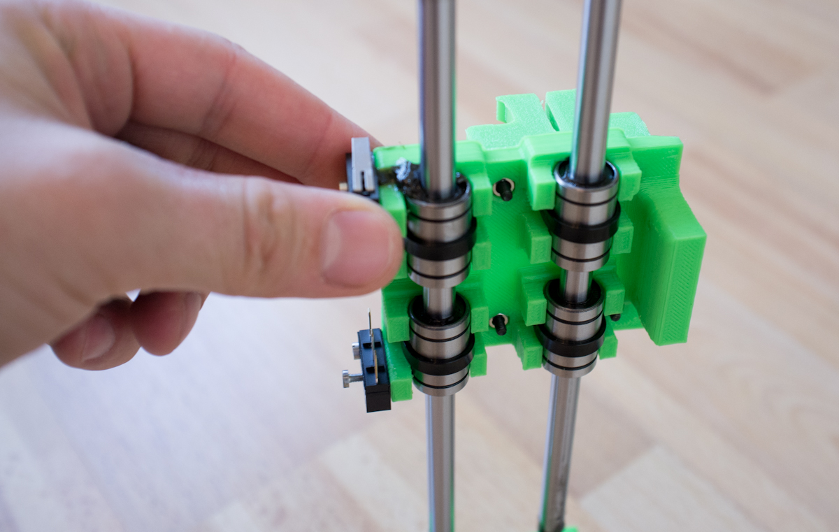
It fast became clear that this would not work as intended. As you can see in the picture above, there is nothing to drive in the Y-direction on the right side. We totally relied on the slider between the X and Y axis on the right side to hold a perfect 90 degree angle. That did not happen.
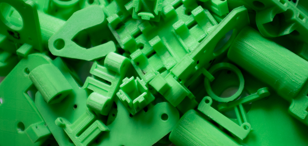
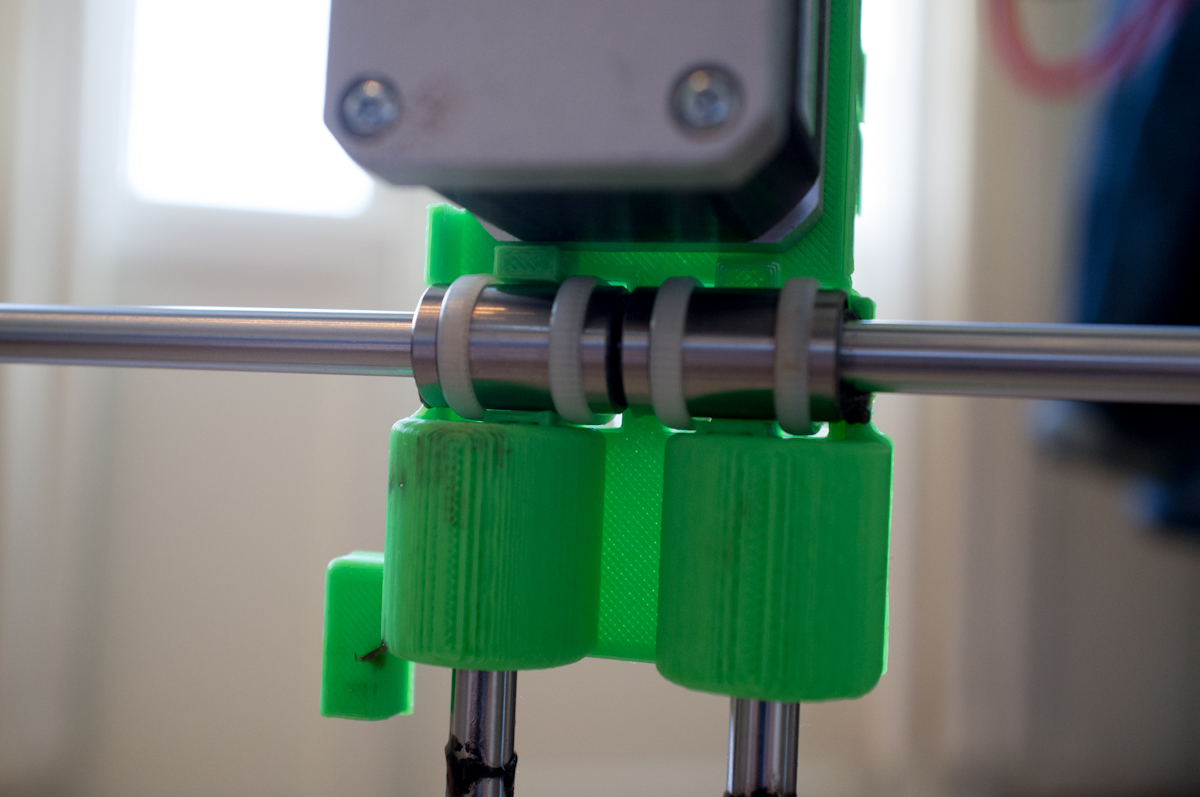
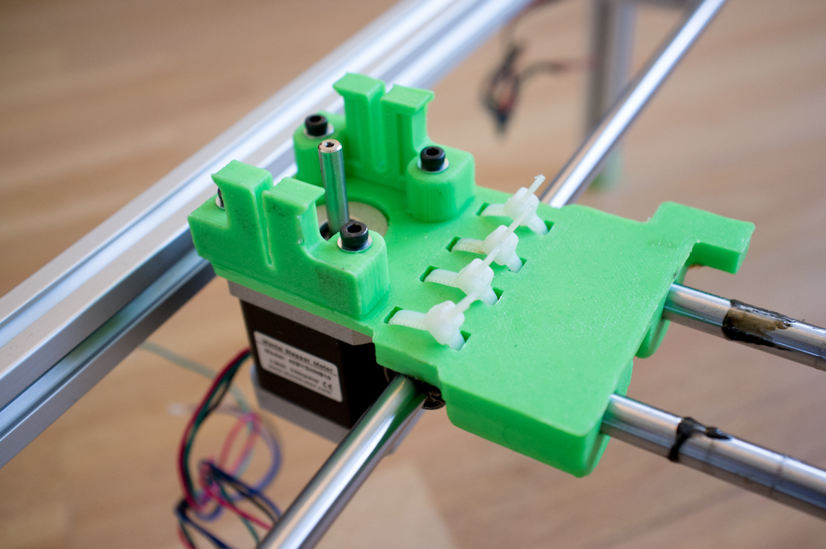
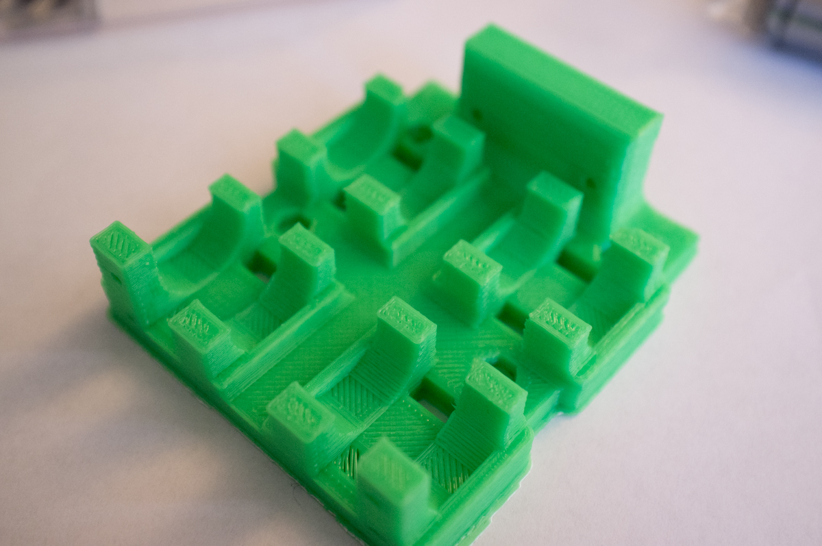
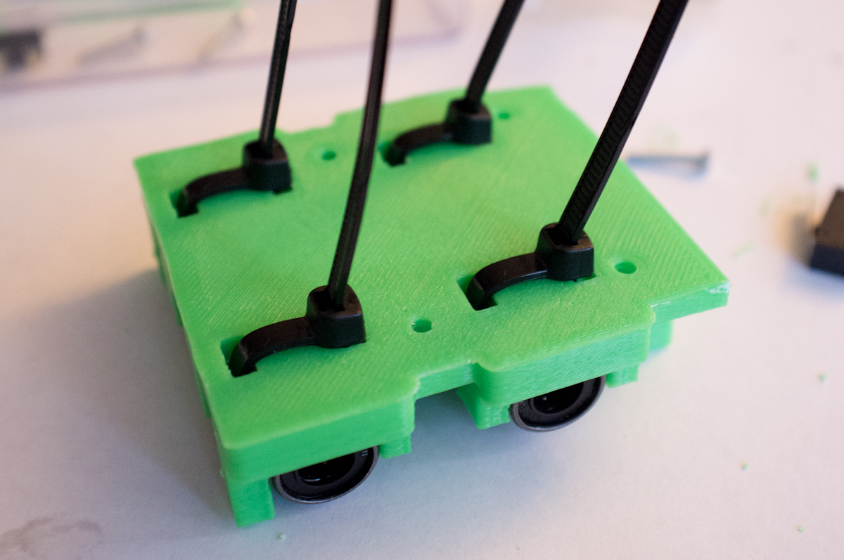
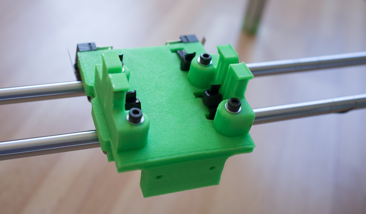
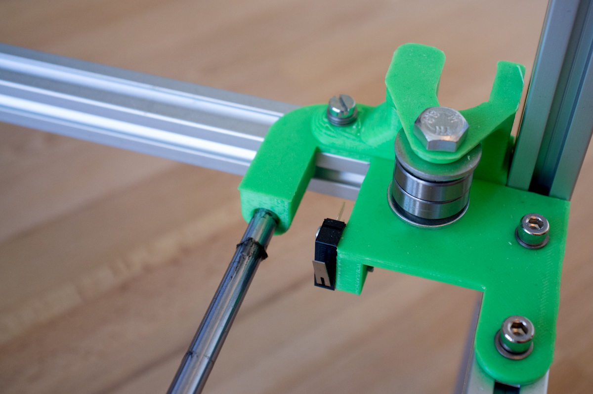
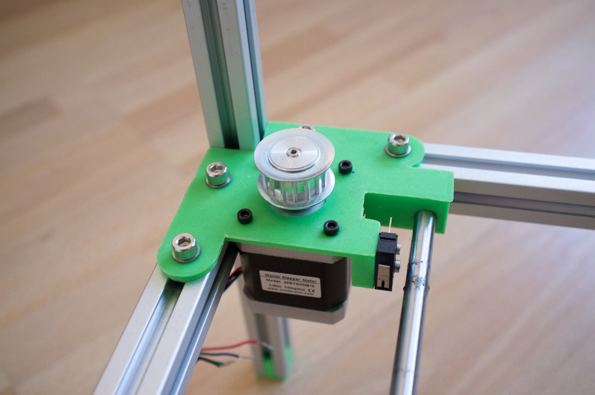
So we went back to the drawing board, with knowledge about the need for synchronous moving sliders. But anyways, here are some more pictures of the parts we created for the first (failed) edition:
So how did we solve this? We will show that in the next post together with a deeper dive into the system architecture. And maybe a video?
The machine is going to take part of Pstereo Mini Maker Faire (Trondheim, Norway) 17 August, so check it out there if you are in town!
Continue to the next part showing the finished laser engraver in action here!